EP1103679A2 - Einsteckschloss zur Befestigung in einer Tür oder dergleichen - Google Patents
Einsteckschloss zur Befestigung in einer Tür oder dergleichen Download PDFInfo
- Publication number
- EP1103679A2 EP1103679A2 EP00203763A EP00203763A EP1103679A2 EP 1103679 A2 EP1103679 A2 EP 1103679A2 EP 00203763 A EP00203763 A EP 00203763A EP 00203763 A EP00203763 A EP 00203763A EP 1103679 A2 EP1103679 A2 EP 1103679A2
- Authority
- EP
- European Patent Office
- Prior art keywords
- bolt
- conveying element
- case
- actuating arm
- mortise lock
- Prior art date
- Legal status (The legal status is an assumption and is not a legal conclusion. Google has not performed a legal analysis and makes no representation as to the accuracy of the status listed.)
- Granted
Links
- 230000006835 compression Effects 0.000 abstract description 2
- 238000007906 compression Methods 0.000 abstract description 2
- 230000000903 blocking effect Effects 0.000 description 1
- 238000010276 construction Methods 0.000 description 1
- 239000002184 metal Substances 0.000 description 1
- 230000035515 penetration Effects 0.000 description 1
- 230000003313 weakening effect Effects 0.000 description 1
Images

Classifications
-
- E—FIXED CONSTRUCTIONS
- E05—LOCKS; KEYS; WINDOW OR DOOR FITTINGS; SAFES
- E05B—LOCKS; ACCESSORIES THEREFOR; HANDCUFFS
- E05B63/00—Locks or fastenings with special structural characteristics
- E05B63/0017—Locks with sliding bolt without provision for latching
- E05B63/0021—Locks with sliding bolt without provision for latching the bolt being shot over an increased length by a single turning operation of the key
Definitions
- the invention relates to a mortise lock for mounting in a door or the like, comprising a case in which a bolt is slidably received, an actuating arm being connected to an inner cylinder which is mounted within an outer cylinder being fixedly connected to said case and being rotatable with the help of a key, a conveying element being present for cooperating with the actuating arm and said element being slidable together with said bolt and also transversely to its direction of movement and being pushed into the direction of the actuating arm by means of a spring, said conveying element being provided with a guide member cooperating with guiding means mounted within the case.
- Such a lock is known from US 5 678 432.
- the conveying element has a U-shaped cross-section and falls across a part of the bolt.
- the body of the U is provided with a laterally projecting portion, which can be contacted with obliquely extending guiding surfaces so that, after the conveying element has come out of engagement with the actuating arm, the conveying element can press the bolt further outwards.
- the object of the invention is to overcome these drawbacks and to that end provides for, that a part of the bolt, connecting to the part which can be located entirely outside of the lock, is fittingly received in the case of the lock and is provided with a recess having two side walls extending square to the longitudinal direction of the bolt, with the conveying element, having almost the same thickness as the bolt, being slidably received in said recess, in which at least one pin for guiding the conveying element is connected to the conveying element or the wall of the case and is guided in a bent slot which has been made in the case or in the conveying element.
- a robust structure is obtained, while the friction between the parts is limited as much as possible.
- both lateral surfaces of the conveying element can be provided with one pin, said pins being offset in relation to one another, and each of the lateral walls of the case engaging them can be provided with a slot.
- each slot has an oppositely bent portion into which a pin connected to the conveying element can be received when the bolt is pushed back into the case without using the key.
- the bolt when the key is not used, the bolt can not be pushed into the case, since then the conveying element will provide a blocking of the bolt.
- US 5 317 890 is referred to, which discloses a lock likewise using a conveying element for pushing the bolt of the lock further outwards when this can no longer be done by the actuating arm.
- a bore is made in the bolt, extending square to its direction of movement, in which bore a spring-biased pin is mounted.
- the pin is provided with a further pin being transverse to the plane of the bolt, said second pin being guided by a slot made in a wall of the case. The bolt will get weakened by the slot and the other parts can only be of limited dimensions.
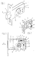
- the drawing shows a mortise lock comprising a case 1 in which a bolt 2 is slidably received.
- the case 1 is defined by the lateral walls 3, in which one of said walls can be connected to the transverse walls 4, so that a housing 5 is formed, to which the other lateral wall 3 can be fixed by means of screws.
- the housing 5 is provided with a cross-plate 6, with which the lock can be fastened to a door or the like by means of screws.
- the bolt 2 comprises a part 7 which is fittingly and slidingly received in the case 1, and a part 8 which can project outwards through the cross-plate 6.
- a recess 9 in the part 7 of the bolt 2 holds a conveying element 10, which is slidable in the plane of the bolt 2 and transverse to its direction of movement V, see fig. 3.
- the conveying element 10 is spring-loaded by means of a compression spring 11.
- a pin 13 is mounted on each lateral wall 12 of the conveying element 10 and each pin 13 is received in a slot 14 in one of the lateral walls 3 of the case 1.
- the pins 13 are offset in relation to each other and obviously this also applies to the slots 14 in which they are located.
- a slot 14 is provided with an oppositely bent part 15, in which the accompanying pin 13 will fall when an inwardly directed force is exerted on part 8 of the bolt 2 in particular.
- the inward movement of the bolt 2 is limited by the slots 14, possibly in combination with the transverse wall 4 the of case 1, indicated in Figure 3.
- Holes 16 are present for fastening a possibly applicable metal work on the door.
- An outer cylinder 17 is fixedly mounted in the case 1 and the inner cylinder 18 is rotatable within said outer cylinder 17. Rotation of the inner cylinder 18 takes place in a known way with the help of a key 19 providing for deblocking of the inner cylinder 18.
- the key 19 can only be inserted in the inner cylinder 18 when the latter is in the position shown in Figure 2.
- the actuating arm 20 connected to it will at a given moment be received in a cavity 21 of the conveying element 10, as illustrated in Figure 3.
- the actuating arm 20 now starts acting on the conveying element 10, causing it to be pushed to the left, as seen in Figure 3. Further, the conveying element 10 wil move upward, also due to the pins 13 received in the slots 14. With that, the spring 11 will be compressed.
- the key 19 can be turned further, so that it will have been rotated across 360 degrees in total, and can then be taken out of the lock.
- the actuating arm 20 can be rotated in the direction of the arrow R so that the arm will again be received in the cavity 21 of the conveying element 10.
- Conveying element 10 can then be moved upwards and to the right in order to pull the bolt 2 back into the case 1.
- the lock can be designed in such a way, that the actuating arm can be rotated from both sides of the lock.
Landscapes
- Engineering & Computer Science (AREA)
- Structural Engineering (AREA)
- Lock And Its Accessories (AREA)
- Connection Of Plates (AREA)
- Hinges (AREA)
Applications Claiming Priority (2)
| Application Number | Priority Date | Filing Date | Title |
|---|---|---|---|
| NL1013645 | 1999-11-23 | ||
| NL1013645A NL1013645C2 (nl) | 1999-11-23 | 1999-11-23 | Insteekslot voor aanbrenging in een deur of dergelijke. |
Publications (3)
| Publication Number | Publication Date |
|---|---|
| EP1103679A2 true EP1103679A2 (de) | 2001-05-30 |
| EP1103679A3 EP1103679A3 (de) | 2007-01-10 |
| EP1103679B1 EP1103679B1 (de) | 2010-01-06 |
Family
ID=19770308
Family Applications (1)
| Application Number | Title | Priority Date | Filing Date |
|---|---|---|---|
| EP20000203763 Expired - Lifetime EP1103679B1 (de) | 1999-11-23 | 2000-10-27 | Einsteckschloss zur Befestigung in einer Tür oder dergleichen |
Country Status (2)
| Country | Link |
|---|---|
| EP (1) | EP1103679B1 (de) |
| NL (1) | NL1013645C2 (de) |
Cited By (2)
| Publication number | Priority date | Publication date | Assignee | Title |
|---|---|---|---|---|
| WO2005054608A1 (en) * | 2003-11-21 | 2005-06-16 | Architectural Products & Components | A mortice lock |
| GB2430005A (en) * | 2005-09-08 | 2007-03-14 | Assa Abloy Ltd | Lock assembly with increased bolt throw |
Citations (1)
| Publication number | Priority date | Publication date | Assignee | Title |
|---|---|---|---|---|
| US5317890A (en) | 1992-11-16 | 1994-06-07 | Wu Danny K T | Mortise lock latch assembly |
Family Cites Families (5)
| Publication number | Priority date | Publication date | Assignee | Title |
|---|---|---|---|---|
| GB8705561D0 (en) * | 1987-03-10 | 1987-04-15 | Parkes Josiah & Sons Ltd | Locks |
| DE3807338A1 (de) * | 1988-03-05 | 1989-09-14 | Schulte Schlagbaum Ag | Schloss, insbesondere einsteckschloss |
| DE3825457A1 (de) * | 1988-07-27 | 1990-02-01 | Bks Gmbh | Riegelschloss, insbesondere einsteckschloss |
| HUH3880A (hu) * | 1994-10-18 | 1999-02-01 | János Fehérdi | Zárszerkezet |
| US5678432A (en) * | 1995-07-20 | 1997-10-21 | Gregg Teskey | Extended throw deadbolt lock assembly |
-
1999
- 1999-11-23 NL NL1013645A patent/NL1013645C2/nl not_active IP Right Cessation
-
2000
- 2000-10-27 EP EP20000203763 patent/EP1103679B1/de not_active Expired - Lifetime
Patent Citations (1)
| Publication number | Priority date | Publication date | Assignee | Title |
|---|---|---|---|---|
| US5317890A (en) | 1992-11-16 | 1994-06-07 | Wu Danny K T | Mortise lock latch assembly |
Cited By (2)
| Publication number | Priority date | Publication date | Assignee | Title |
|---|---|---|---|---|
| WO2005054608A1 (en) * | 2003-11-21 | 2005-06-16 | Architectural Products & Components | A mortice lock |
| GB2430005A (en) * | 2005-09-08 | 2007-03-14 | Assa Abloy Ltd | Lock assembly with increased bolt throw |
Also Published As
| Publication number | Publication date |
|---|---|
| NL1013645C2 (nl) | 2001-05-28 |
| EP1103679A3 (de) | 2007-01-10 |
| EP1103679B1 (de) | 2010-01-06 |
Similar Documents
| Publication | Publication Date | Title |
|---|---|---|
| US5318333A (en) | Device for locking and unlocking sashes in door- or window frames | |
| US4566725A (en) | Deadlock mechanism | |
| US7716960B2 (en) | Lock device | |
| KR960029575A (ko) | 다중점 체결장치 | |
| US5317890A (en) | Mortise lock latch assembly | |
| US8066309B2 (en) | Latch | |
| FI75209C (fi) | Laosanordning. | |
| EP1103679A2 (de) | Einsteckschloss zur Befestigung in einer Tür oder dergleichen | |
| US4927195A (en) | Dual backset deadbolt assembly | |
| EP0278704A2 (de) | Verriegelungsvorrichtung mit mehreren Riegeln | |
| GB2134960A (en) | Locking device | |
| US6739162B1 (en) | Simple deadbolt assembly | |
| US6089625A (en) | Fitting for sliding closure | |
| US4964662A (en) | Portable door securing device | |
| US20040017087A1 (en) | Latch apparatus | |
| KR100441850B1 (ko) | 인출 회전조작형 문용 로크핸들장치 | |
| AU564698B2 (en) | Locking device | |
| JP2656999B2 (ja) | 突放しばねを備えた改良型反動掛合動作式ラッチ | |
| JP3515212B2 (ja) | キー装置 | |
| GB2559377A (en) | Lock apparatus | |
| US6877783B2 (en) | Latch | |
| RU2100669C1 (ru) | Устройство для разъемного соединения профильных стержней с отверстиями в зоне их соединения | |
| GB2327457A (en) | Shoot bolt fastening for windows or doors | |
| US1634634A (en) | Latch and keeper means | |
| GB2202892A (en) | Double cylinder lock assembly |
Legal Events
| Date | Code | Title | Description |
|---|---|---|---|
| PUAI | Public reference made under article 153(3) epc to a published international application that has entered the european phase |
Free format text: ORIGINAL CODE: 0009012 |
|
| AK | Designated contracting states |
Kind code of ref document: A2 Designated state(s): AT BE CH CY DE DK ES FI FR GB GR IE IT LI LU MC NL PT SE |
|
| AX | Request for extension of the european patent |
Free format text: AL;LT;LV;MK;RO;SI |
|
| RAP1 | Party data changed (applicant data changed or rights of an application transferred) |
Owner name: J.W. VAN DER WAL BEHEER B.V. |
|
| PUAL | Search report despatched |
Free format text: ORIGINAL CODE: 0009013 |
|
| AK | Designated contracting states |
Kind code of ref document: A3 Designated state(s): AT BE CH CY DE DK ES FI FR GB GR IE IT LI LU MC NL PT SE |
|
| AX | Request for extension of the european patent |
Extension state: AL LT LV MK RO SI |
|
| RIC1 | Information provided on ipc code assigned before grant |
Ipc: E05B 63/00 20060101AFI20061201BHEP |
|
| 17P | Request for examination filed |
Effective date: 20070207 |
|
| AKX | Designation fees paid |
Designated state(s): BE GB NL |
|
| REG | Reference to a national code |
Ref country code: DE Ref legal event code: 8566 |
|
| 17Q | First examination report despatched |
Effective date: 20080421 |
|
| GRAP | Despatch of communication of intention to grant a patent |
Free format text: ORIGINAL CODE: EPIDOSNIGR1 |
|
| GRAS | Grant fee paid |
Free format text: ORIGINAL CODE: EPIDOSNIGR3 |
|
| GRAA | (expected) grant |
Free format text: ORIGINAL CODE: 0009210 |
|
| AK | Designated contracting states |
Kind code of ref document: B1 Designated state(s): BE GB NL |
|
| REG | Reference to a national code |
Ref country code: GB Ref legal event code: FG4D |
|
| REG | Reference to a national code |
Ref country code: NL Ref legal event code: T3 |
|
| PLBE | No opposition filed within time limit |
Free format text: ORIGINAL CODE: 0009261 |
|
| STAA | Information on the status of an ep patent application or granted ep patent |
Free format text: STATUS: NO OPPOSITION FILED WITHIN TIME LIMIT |
|
| 26N | No opposition filed |
Effective date: 20101007 |
|
| GBPC | Gb: european patent ceased through non-payment of renewal fee |
Effective date: 20101027 |
|
| PG25 | Lapsed in a contracting state [announced via postgrant information from national office to epo] |
Ref country code: GB Free format text: LAPSE BECAUSE OF NON-PAYMENT OF DUE FEES Effective date: 20101027 |
|
| PGFP | Annual fee paid to national office [announced via postgrant information from national office to epo] |
Ref country code: BE Payment date: 20131011 Year of fee payment: 14 |
|
| PG25 | Lapsed in a contracting state [announced via postgrant information from national office to epo] |
Ref country code: BE Free format text: LAPSE BECAUSE OF NON-PAYMENT OF DUE FEES Effective date: 20141031 |
|
| REG | Reference to a national code |
Ref country code: NL Ref legal event code: PD Owner name: M. VAN DER WAL HOLDING B.V.; NL Free format text: DETAILS ASSIGNMENT: CHANGE OF OWNER(S), ASSIGNMENT; FORMER OWNER NAME: J.W. VAN DER WAL BEHEER B.V. Effective date: 20180503 |
|
| PGFP | Annual fee paid to national office [announced via postgrant information from national office to epo] |
Ref country code: NL Payment date: 20191029 Year of fee payment: 20 |
|
| REG | Reference to a national code |
Ref country code: NL Ref legal event code: MK Effective date: 20201026 |