EP1103225A2 - Chirurgisches Instrument zum Spannen eines Kabelartigen Spannelements - Google Patents
Chirurgisches Instrument zum Spannen eines Kabelartigen Spannelements Download PDFInfo
- Publication number
- EP1103225A2 EP1103225A2 EP00810994A EP00810994A EP1103225A2 EP 1103225 A2 EP1103225 A2 EP 1103225A2 EP 00810994 A EP00810994 A EP 00810994A EP 00810994 A EP00810994 A EP 00810994A EP 1103225 A2 EP1103225 A2 EP 1103225A2
- Authority
- EP
- European Patent Office
- Prior art keywords
- lever
- instrument according
- levers
- tensile force
- actuating
- Prior art date
- Legal status (The legal status is an assumption and is not a legal conclusion. Google has not performed a legal analysis and makes no representation as to the accuracy of the status listed.)
- Granted
Links
- 238000005259 measurement Methods 0.000 claims abstract description 6
- 238000003780 insertion Methods 0.000 claims description 11
- 230000037431 insertion Effects 0.000 claims description 11
- 230000005291 magnetic effect Effects 0.000 claims description 11
- 238000005452 bending Methods 0.000 claims description 4
- 239000013078 crystal Substances 0.000 claims description 4
- 238000001356 surgical procedure Methods 0.000 claims description 4
- 230000005294 ferromagnetic effect Effects 0.000 claims description 2
- 230000003993 interaction Effects 0.000 claims description 2
- 230000004075 alteration Effects 0.000 abstract 3
- 238000003825 pressing Methods 0.000 description 3
- 230000006835 compression Effects 0.000 description 2
- 238000007906 compression Methods 0.000 description 2
- 238000011156 evaluation Methods 0.000 description 2
- 239000004033 plastic Substances 0.000 description 2
- 238000003892 spreading Methods 0.000 description 2
- 239000004809 Teflon Substances 0.000 description 1
- 229920006362 Teflon® Polymers 0.000 description 1
- 230000003321 amplification Effects 0.000 description 1
- 239000002131 composite material Substances 0.000 description 1
- 230000007423 decrease Effects 0.000 description 1
- 230000001419 dependent effect Effects 0.000 description 1
- 238000005516 engineering process Methods 0.000 description 1
- 210000003746 feather Anatomy 0.000 description 1
- 239000012774 insulation material Substances 0.000 description 1
- 238000004519 manufacturing process Methods 0.000 description 1
- 239000000463 material Substances 0.000 description 1
- 239000002184 metal Substances 0.000 description 1
- 238000003199 nucleic acid amplification method Methods 0.000 description 1
- 206010039722 scoliosis Diseases 0.000 description 1
- 229920002379 silicone rubber Polymers 0.000 description 1
- 239000004945 silicone rubber Substances 0.000 description 1
Images


Classifications
-
- A—HUMAN NECESSITIES
- A61—MEDICAL OR VETERINARY SCIENCE; HYGIENE
- A61B—DIAGNOSIS; SURGERY; IDENTIFICATION
- A61B17/00—Surgical instruments, devices or methods
- A61B17/56—Surgical instruments or methods for treatment of bones or joints; Devices specially adapted therefor
- A61B17/58—Surgical instruments or methods for treatment of bones or joints; Devices specially adapted therefor for osteosynthesis, e.g. bone plates, screws or setting implements
- A61B17/88—Osteosynthesis instruments; Methods or means for implanting or extracting internal or external fixation devices
- A61B17/8869—Tensioning devices
-
- A—HUMAN NECESSITIES
- A61—MEDICAL OR VETERINARY SCIENCE; HYGIENE
- A61B—DIAGNOSIS; SURGERY; IDENTIFICATION
- A61B17/00—Surgical instruments, devices or methods
- A61B17/56—Surgical instruments or methods for treatment of bones or joints; Devices specially adapted therefor
- A61B17/58—Surgical instruments or methods for treatment of bones or joints; Devices specially adapted therefor for osteosynthesis, e.g. bone plates, screws or setting implements
- A61B17/88—Osteosynthesis instruments; Methods or means for implanting or extracting internal or external fixation devices
- A61B17/8861—Apparatus for manipulating flexible wires or straps
-
- A—HUMAN NECESSITIES
- A61—MEDICAL OR VETERINARY SCIENCE; HYGIENE
- A61B—DIAGNOSIS; SURGERY; IDENTIFICATION
- A61B90/00—Instruments, implements or accessories specially adapted for surgery or diagnosis and not covered by any of the groups A61B1/00 - A61B50/00, e.g. for luxation treatment or for protecting wound edges
- A61B90/06—Measuring instruments not otherwise provided for
- A61B2090/064—Measuring instruments not otherwise provided for for measuring force, pressure or mechanical tension
Definitions
- the invention relates to a surgical instrument for tensioning a cable, band-like or cord-like tensioning element.
- the tensioning element can, for example, be one made of metal wires Cable, a thread composite formed from plastic filaments or a linear wickerwork of yarns. Such a clamping element is also briefly referred to as a band.
- Dwyer For the surgical treatment of backbone curvatures (scoliosis) Dwyer has developed a surgical technique in which the patient's body by means of cables and screws a sequence of neighboring vertebrae into one stiffened part of the spine.
- a cable tensioner is used. From GB-A-1 551 707 such a device is known.
- This cable tensioning device comprises a first one lever-like part and a second part, which acts as a gripper element for the cable is trained. These two parts are connected by a main joint connected.
- the second part is a lever system in which levers have three Joints are interconnected. Two of these levers form one Clamping gap of the gripper element.
- the lever system consists of two hinged by a third lever connected actuating levers and arranged between the levers Feathers. Thereby a stable basic position of the system by the under mechanical tension springs and by between the Actuating levers and the third lever acting Movement limits given.
- At the top of the first Actuating lever is an insertion opening for the tensioning element and on one Tip of the second actuating lever a first jaw to a clamping gap arranged for the clamping element.
- a second jaw to this nip is on the third lever.
- the clamping element In the basic position of the system the clamping element in the insertion opening of the first actuating lever and Push it into the clamping gap on the second operating lever.
- the third Lever is symmetrical as a bracket with two side plates, the Actuating lever between the side plates on the pivot pin are arranged and the bearing bolts in bores of the two side plates are attached.
- the jaw is located at the apex of the bracket of the third lever. Together with the other jaw and parts of the Side plates are given a laterally closed channel for the belt. At this system consisting of three levers proved to be the production of the Spherical bearings as expensive.
- It is an object of the invention to use a tape tensioner To create an instrument that is designed as a three-lever system so that the tensile force acting on the belt can be determined. Furthermore a form of this instrument is to be created for which the Assemble the instrument from the three levers without any particular problems leaves.
- the first subtask is defined by that in claim 1 or 2 Instrument released; Both subtasks are performed by the instrument Claim 3 or 4 solved.
- the surgical instrument for tensioning a cable, tape or cord-like tensioning element comprises a manually operated lever system. There are two levers - the first and the second actuation lever - by one third lever articulated. In a basic position of the system that is Clamping element in an insertion opening of the first and in a clamping gap second and third lever can be inserted. One of the operating levers is in one Section formed as a flexible beam. The extent of one The change in shape of the bar is measurable. A relationship between this Shape change and a tensile force in the clamping element is known. Because of this knowledge and a measurement of the shape change is the tensile force adjustable.
- the basic position is preferably a stable one Location, namely due to at least one between the levers arranged spring or due to another, corresponding forces exercising means.
- the third lever is asymmetrical and has only one side plate on. Bearing bolts for two lever joints are part of the third lever.
- a Embodiment is a single spring attached to the third lever.
- a The jaw of the third lever is the base of a U-shaped channel.
- the spring has two legs, each under a mechanical Apply tension to the inner flanks of the operating levers.
- a jaw of the second lever plunges into the U-shaped channel.
- One between the second and third lever acting movement limit is through given a separately insertable stop pin.
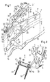
- the instrument according to the invention shown in FIG. 1, the band tensioner comprises a lever system, which consists of two levers 1 and 2, which by a third lever 3 are connected to joints 11 and 22.
- the Instrument is asymmetrical; the visible side is different of the invisible, which is in the lower half of Fig. 1 as a mirror image is shown (whereby only the areas of the lowest page level are shown are and the handles 10 and 20 are partially indicated by dash-dotted lines).
- a tip 13 of the first actuating lever 1 there is an insertion opening 15 for a cable, band or cord-like tensioning element or short band 5 - see Fig. 2 - arranged.
- a tip 33 of the third lever 3 is one first jaw 33 'arranged to a clamping gap 32 for the band 5.
- a second jaw 23 'to this clamping gap 32 is located at one end 23 of the second operating lever 2. In the basic position of the system the band 5 into the insertion opening 15 of the first actuating lever 1 as well as in the clamping gap 32 on the second actuating lever 2.
- Fig. 2 shows the front part of the instrument according to the invention, with the the band 5 is put under a tensile force by said spreading movement has been.
- the band 5 is with a cylindrical screw 63 in the head 64 a first pedicular screw 61 fixed.
- Volume 5 from the first Pedicular screw 61 through a plastic tube 60 (so-called cushion) for Head 64 'of a second pedicular screw 62 leads there in the cocked Condition can be fixed with another cylindrical screw 63 '.
- the third lever 3 - see Fig. 3 - is asymmetrical with only one side plate 30 trained.
- Bearing bolts 110, 220 for the two lever joints 11, 22 are Parts of the third lever 3.
- the actuating levers 1 and 2 that hold the bolt have corresponding bores, are on the bolts 110, 220 attached, whereby rotatable connections are made with screws.
- the clamping jaw 33 'of the third lever 3 forms the base 330 of a U-shaped one Channel.
- the jaw 23 'of the second lever 2 is immersed in the U-shaped Channel one.
- the between the second operating lever 2 and the third lever 3 acting movement limit is separated by a insertable stop pin 35 given.
- the operating lever 2 can geometrical reasons only composed with the third lever 3 if the stop pin 35 is still missing.
- the spring 4 is on the third lever 3 with a screw 34 - see Fig. 2 - attached. It has two legs 41 and 42, each under one mechanical tension on the inner flanks 43 of the actuating levers 1 and 2 abut, the legs 41 and 42 sliding in grooves of the inner flanks 43 can.
- the insertion opening 13 of the first actuating lever 1 is an eyelet; but it can also be fork-shaped as a gap between two prongs his.
- the jaws 23 'and 33' of the clamping gap 32 advantageously have Clamping surfaces 230, 330 ribs, with rib edges preferably are oriented transversely to the direction of the tensile force acting on the belt 5.
- the operating lever 2 is on the side of the handle 20 along one Section designed as a flexible beam 20 ': see Figures 1 and 5.
- the extent of a change in shape of the bar 20 ' can be measured.
- a Relationship between this change in shape and a tensile force in band 5 is determinable and assumed to be known.
- the tensile force in band 5 controllable and thus adjustable.
- the flexible beam 20 ' is arranged next to a reference beam 21.
- the two bars 20 'and 21 extend parallel to one another along one Gaps 210. Segments 20a and 21a with the bars are transverse to the gap 210 20 'and 21 connected.
- markings 209a, 209b, 210 on the Segments 20a and 21a attached to determine the change in shape.
- the marking lines 209b and 210 are attached, for example, that this does not exceed a tensile force in band 5 that is not exceeded should be on a common straight line - cf. Fig. 5 - come to rest.
- the marking line 209a can indicate a zero point for which the band 5 is already fixed in the clamping gap 32 without already having a tensile force works. It can be provided that the markings are made separately mountable papers. These papers can be one Corresponding to the zero point, which is determined empirically, can be mounted.
- a bending restriction is illustrated in FIG. 5: the end 20b of the segment 20a is hook-shaped.
- a sensor in particular a sensor, can be placed on the flexible beam 20 ' Strain gauges 8 may be attached.
- the sensor is part of an electrical and / or electronic measuring device for displaying those acting in band 5 Traction (not shown).
- the meter can be on or in Actuating lever on which the sensor is arranged can be integrated.
- the Actuating lever 2 is composed of a handle part 20 and a front part 20 " two screws 28 put together. One on two flanks flexible beam 20 ', two strain gauges 8a, 8b are attached. Two soft cover layers 80a are used to encapsulate these sensors, 80b, their influence on the shape change of the bar 20 'is practical is negligible.
- a cam 207 and a bar 208 act as Bending restriction for the purpose of overload protection.
- FIG. 7 shows a further possibility for checking the tensile force in band 5 shown; namely a means for determining the torque that the Tensioning the band 5 on the actuating lever 2 acts.
- This lever 2 is also from a handle part 20 and a front part 20 " assembled, but here via a hinge 29.
- Measuring chains between the sensors and display devices can still the following remarks are added:
- the display device there is a Signal evaluation.
- the display of the result of this signal evaluation takes place optically and / or acoustically.
- the sensor is a strain gauge, it is a power supply is required.
- the sensor is a piezo crystal, it is Possibility of zero adjustment required.
- a measurement amplifier for one Voltage or current signal (strain gauge) or for one Charge amplification (piezo crystal) can be in the instrument or in the display device be integrated.
- the strain gauges can be used as half or full bridges be switched.
- a cable for the connection between the measuring amplifier and display device must be steam-sterilisable and have a kink protection exhibit.
- Preferred materials for the insulation material are Silicone rubber and / or teflon.
- Interfaces instrument cable and cable display device must be suitable for medical technology applications, d. H. are in the form of plug connections that can be sterilized and are hermetically sealed. The instrument-cable interface can take place be detachable also firm.
- FIG. 8 An alternative to the mechanical embodiment of Figures 1 to 5, d. H. the example of the tape tensioner according to the invention, in which with a mechanical display shows the tensile force in the band to be tensioned 5 is checked is shown in Fig. 8.
- a reference bar 12 is a second part of the front area. At the base of this reference bar 12 there is the joint 11, which is the connection between the Operating lever 1 and the third lever 3 produces.
- a distance a decreases between the bars 10 'and 12 at their tips 13a and 13b (proportional to traction).
- a distance a given in the basic position is advantageous set so large that the bars 10 'and 12 when reaching one Touch the desired traction, d. H. the distance a becomes zero.
- Both bars 10 'and 12 contain insertion openings 15a and 13a, 13b at their tips. 15b for the band 5. Since the surgeon only needs the distance a during an operation hard to see, the first mechanical embodiment is the one in FIG Fig. 8 preferred alternative.
- FIG. 9 shows a further alternative, in which the spring 4 passes through Magnetic elements 45, 46 and 47 is substituted with magnetic Attractions interact. At least one of these Magnetic element is a permanent magnet 45; the other or the other Magnetic elements 46 and 47 are ferromagnetic.
- the permanent magnet 45 or one of the permanent magnets is in the first actuating lever 1, there in Area between the insertion opening 15 and the lever joint 11, arranged; and the other or the other magnetic elements 46 and 47 are in appropriate positions in the second operating lever or in the third Lever arranged.
Landscapes
- Health & Medical Sciences (AREA)
- Life Sciences & Earth Sciences (AREA)
- Orthopedic Medicine & Surgery (AREA)
- Surgery (AREA)
- Biomedical Technology (AREA)
- Engineering & Computer Science (AREA)
- Nuclear Medicine, Radiotherapy & Molecular Imaging (AREA)
- Heart & Thoracic Surgery (AREA)
- Medical Informatics (AREA)
- Molecular Biology (AREA)
- Animal Behavior & Ethology (AREA)
- General Health & Medical Sciences (AREA)
- Public Health (AREA)
- Veterinary Medicine (AREA)
- Surgical Instruments (AREA)
Abstract
Description
- Fig. 1
- ein erfindungsgemässes Instrument,
- Fig. 2
- den vorderen Teil dieses Instruments mit einem unter eine Zugkraft gesetzten Band,
- Fig. 3
- ein dritter Hebel des erfindungsgemässen Instruments,
- Fig. 4
- den vorderen Teil des Instruments mit festgeklemmtem Band,
- Fig. 5 - 7
- Ausschnitte jeweils aus einem zweiten Betätigungshebel mit Mitteln zur Durchführung einer Kraftmessung,
- Fig. 8
- eine Alternative zum mechanischen Ausführungsbeispiel der Figuren 1 bis 5 und
- Fig. 9
- eine weitere Alternative, bei der die Feder durch Magnetelemente substituiert ist.
Claims (12)
- Chirurgisches Instrument zum Spannen eines kabel-, band- oder schnurartigen Spannelements (5), ein manuell betätigbares Hebelsystem umfassend, mit zwei durch einen dritten Hebel (3) gelenkig verbundenen Hebeln (1, 2) - dem ersten und dem zweiten Betätigungshebel -, wobei in einer Grundstellung des Systems das Spannelement in eine Einlegeöffnung (15) des ersten und in einen Klemmspalt (32) am zweiten sowie dritten Hebel einlegbar ist, dadurch gekennzeichnet, dass einer der Betätigungshebel (2) in einem Abschnitt als biegeelastischer Balken (20', 10') ausgebildet ist, das Ausmass einer Formänderung des Balkens messbar ist, eine Beziehung zwischen dieser Formänderung und einer Zugkraft im Spannelement bekannt ist und aufgrund dieser Kenntnis und einer Messung (209, 211; 8) der Formänderung die Zugkraft einstellbar ist; oder dass ein dem gleichen Zweck dienendes Mittel (9) zur Bestimmung eines an dem entsprechenden Betätigungshebel (2) wirkenden Drehmoments vorgesehen ist.
- Instrument nach Anspruch 1, dadurch gekennzeichnet, dass die Grundstellung aufgrund von mindestens einer zwischen den Hebeln angeordneten Feder (4) oder aufgrund von einem anderen, entsprechende Kräfte ausübenden Mittel (45, 46, 47) eine stabile Lage darstellt.
- Instrument nach Anspruch 2, dadurch gekennzeichnet, dass der dritte Hebel (3) asymmetrisch, nur eine Seitenplatte (30) aufweisend, ausgebildet ist, Lagerbolzen (110, 220) für zwei Hebelgelenke (11, 22) Teile des dritten Hebels sind, eine einzige Feder (4) am dritten Hebel befestigt ist und eine Klemmbacke (33') des dritten Hebels die Grundfläche eines U-förmigen Kanals (32, 33) ist, wobei die Feder zwei Schenkel (41, 42) aufweist, die jeweils unter einer mechanischen Spannung an Innenflanken (43) der Betätigungshebel (1, 2) anliegen, eine Klemmbacke (23') des zweiten Hebels (2) in den U-förmigen Kanal eintaucht und eine zwischen dem zweiten und dem dritten Hebel wirkende Bewegungsbegrenzung durch einen separat einfügbaren Anschlagstift (35) gegeben ist.
- Instrument nach Anspruch 2 oder 3, dadurch gekennzeichnet, dass die Feder durch Magnetelemente (45, 46, 47) substituiert ist, die mit magnetischen Anziehungskräften aufeinander einwirken, wobei mindestens eines dieser Magnetelemente ein Permanentmagnet (45) ist und das andere oder die anderen Magnetelemente ferromagnetisch sind, der Permanentmagnet oder eines der Permanentmagnete im ersten Betätigungshebel (1), dort im Bereich zwischen der Einlegeöffnung (15) und dem Hebelgelenk (11), angeordnet ist und das andere oder die anderen Magnetelemente an entsprechenden Stellen im zweiten Betätigungshebel (2) bzw. im dritten Hebel (3) angeordnet sind.
- Instrument nach einem der Ansprüche 1 bis 4, dadurch gekennzeichnet, dass der biegeelastische Balken (20') neben einem Referenzbalken (21) angeordnet ist, dass die beiden Balken sich im wesentlichen parallel in einer Richtung erstrecken und dass quer zu der Balkenrichtung Segmente (20a, 21a) mit den Balken verbunden sind, auf denen Markierungen (209a, 209b, 211) zur Bestimmung der Formänderung angebracht sind.
- Instrument nach Anspruch 5, dadurch gekennzeichnet, dass das Segment (20a) am biegeelastischen Balken (20') geometrisch so ausgebildet ist, dass sich eine Biegebeschränkung unter einem Zusammenwirken mit dem Segment (20b) am Referenzbalken (21) ergibt.
- Instrument nach einem der Ansprüche 1 bis 7, dadurch gekennzeichnet, dass für die Mittel zur Bestimmung der auf das Spannelement wirkenden Zugkraft ein Sensor (8, 9), insbesondere ein Sensor mit Dehnmessstreifen (8; 8a, 8b) oder Piezokristall (9) vorgesehen ist, und dass der Sensor Teil eines elektrischen und/oder elektronischen Messgeräts zum Anzeigen der im Spannelement wirkenden Zugkraft ist.
- Instrument nach Anspruch 7, dadurch gekennzeichnet, dass am oder im Betätigungshebel (2), auf dem der Sensor (8, 9) angeordnet ist, das Messgerät integriert ist.
- Instrument nach einem der Ansprüche 1 bis 8, dadurch gekennzeichnet, dass die Einlegeöffnung (15) des ersten Betätigungshebels (1) eine Öse oder eine Lücke zwischen zwei Gabelzinken ist.
- Instrument nach einem der Ansprüche 1 bis 9, dadurch gekennzeichnet, dass die Backen (23', 33') des Klemmspalts (32) Rippungen auf den Klemmflächen (330) aufweisen, mit einer Orientierung von Rippungskanten, die vorzugsweise quer zur Richtung der Zugkraft verläuft.
- Instrument nach einem der Ansprüche 1 bis 7, dadurch gekennzeichnet, dass für die Mittel (20a, 21a; 8; 9) zur Bestimmung der auf das Spannelement (5) wirkenden Zugkraft eine Anzeige eines Nullpunkts (209a) vorgesehen ist, wobei diese Nullpunkts-Anzeige einstellbar ist.
- Verwendung eines Instruments gemäss einem der Ansprüche 1 bis 9 zum chirurgischen Behandeln einer Wirbelsäule, wobei Pedikularschrauben (61, 62), die in benachbarten Wirbeln eingesetzt sind, mit einem Band (5) zusammengespannt werden.
Priority Applications (1)
| Application Number | Priority Date | Filing Date | Title |
|---|---|---|---|
| EP00810994A EP1103225B1 (de) | 1999-11-25 | 2000-10-26 | Chirurgisches Instrument zum Spannen eines Kabelartigen Spannelements |
Applications Claiming Priority (5)
| Application Number | Priority Date | Filing Date | Title |
|---|---|---|---|
| EP99811087 | 1999-11-25 | ||
| EP99811087 | 1999-11-25 | ||
| EP99811194 | 1999-12-22 | ||
| EP99811194 | 1999-12-22 | ||
| EP00810994A EP1103225B1 (de) | 1999-11-25 | 2000-10-26 | Chirurgisches Instrument zum Spannen eines Kabelartigen Spannelements |
Publications (3)
| Publication Number | Publication Date |
|---|---|
| EP1103225A2 true EP1103225A2 (de) | 2001-05-30 |
| EP1103225A3 EP1103225A3 (de) | 2002-03-27 |
| EP1103225B1 EP1103225B1 (de) | 2004-09-15 |
Family
ID=27223694
Family Applications (1)
| Application Number | Title | Priority Date | Filing Date |
|---|---|---|---|
| EP00810994A Expired - Lifetime EP1103225B1 (de) | 1999-11-25 | 2000-10-26 | Chirurgisches Instrument zum Spannen eines Kabelartigen Spannelements |
Country Status (1)
| Country | Link |
|---|---|
| EP (1) | EP1103225B1 (de) |
Cited By (2)
| Publication number | Priority date | Publication date | Assignee | Title |
|---|---|---|---|---|
| US7073415B2 (en) | 2003-04-24 | 2006-07-11 | Centerpulse Orthopedics Ltd. | Instrument system for pedicle screws |
| ITPI20080125A1 (it) * | 2008-12-11 | 2010-06-12 | Univ Pisa | Dispositivo per il tensionamento controllato dei fili metallici durante l'esecuzione di un intervento di riduzione di una frattura |
Citations (1)
| Publication number | Priority date | Publication date | Assignee | Title |
|---|---|---|---|---|
| GB1551707A (en) | 1975-04-28 | 1979-08-30 | Downs Surgical Ltd | Surgical instrument |
Family Cites Families (4)
| Publication number | Priority date | Publication date | Assignee | Title |
|---|---|---|---|---|
| CH303821A (de) * | 1952-07-25 | 1954-12-15 | Roland Dr Med Leemann | Spanninstrument. |
| US5540698A (en) * | 1993-04-21 | 1996-07-30 | Amei Technologies Inc. | System and method for securing a medical cable |
| US5782831A (en) * | 1996-11-06 | 1998-07-21 | Sdgi Holdings, Inc. | Method an device for spinal deformity reduction using a cable and a cable tensioning system |
| FR2777449B1 (fr) * | 1998-04-17 | 2000-09-15 | Sulzer Orthopedics Limited | Dispositif de tension pour la pose d'un systeme de stabilisation du rachis |
-
2000
- 2000-10-26 EP EP00810994A patent/EP1103225B1/de not_active Expired - Lifetime
Patent Citations (1)
| Publication number | Priority date | Publication date | Assignee | Title |
|---|---|---|---|---|
| GB1551707A (en) | 1975-04-28 | 1979-08-30 | Downs Surgical Ltd | Surgical instrument |
Cited By (2)
| Publication number | Priority date | Publication date | Assignee | Title |
|---|---|---|---|---|
| US7073415B2 (en) | 2003-04-24 | 2006-07-11 | Centerpulse Orthopedics Ltd. | Instrument system for pedicle screws |
| ITPI20080125A1 (it) * | 2008-12-11 | 2010-06-12 | Univ Pisa | Dispositivo per il tensionamento controllato dei fili metallici durante l'esecuzione di un intervento di riduzione di una frattura |
Also Published As
| Publication number | Publication date |
|---|---|
| EP1103225A3 (de) | 2002-03-27 |
| EP1103225B1 (de) | 2004-09-15 |
Similar Documents
| Publication | Publication Date | Title |
|---|---|---|
| EP2033670B1 (de) | Befestigungsmittel für medizinische Zwecke, insbesondere zum Befestigen einer Referenzgeometrie für navigationsunterstützte Operationen, an einem Körper, insbesondere an einem Knochen | |
| DE3101711C2 (de) | Chirurgisches Gerät zur Dickenmessung von Geweben | |
| DE2203787C3 (de) | Fixator für Diaphysenbruch | |
| DE69023405T2 (de) | Drahthalter und spannvorrichtung. | |
| DE69206318T2 (de) | Verriegelbares Verbindungsstück für Verankerungselemente für die Wirbelsäulenosteosynthese. | |
| DE69918948T2 (de) | Spannvorrichtung für einen nähfaden zum schliessen einer wunde | |
| DE60015183T2 (de) | Gerät zur kompression der unteren gliedmassen zur medizinischen bildgebung | |
| EP1470792A1 (de) | Abstandsmessgerät für Pedikelschrauben | |
| DE69011363T2 (de) | Vorrichtung zum externen Festlegen von Knochenfragmenten mit kontrollierbarer Dämpfung. | |
| EP1827228B1 (de) | Vorrichtung und verfahren zum bestimmen wenigstens eines charakteristischen punktes eines orthopädisch zu vermessenden gelenks | |
| DE102014112161A1 (de) | Biaxiale Messvorrichtung und Verfahren zur Bestimmung von normal- und schubspannungskorrelierten Werkstoffparametern | |
| EP1139871B1 (de) | Vorrichtung und verfahren zur umfangsbestimmung | |
| DE69522864T2 (de) | Messinstrument zur Bestimmung des Relaxierungsgrades | |
| DE3032237C2 (de) | Implantat zur Skoliosebehandlung | |
| DE10049270A1 (de) | Vorrichtung zum Konditionieren eines zu implantierenden Bandes | |
| DE60206583T2 (de) | Hilfsinstrument zur Vorbereitung des Einsetzens einer Knieprothese | |
| EP0100781B1 (de) | Justagevorrichtung für einen Lichtwellenleiter | |
| EP1103225B1 (de) | Chirurgisches Instrument zum Spannen eines Kabelartigen Spannelements | |
| DE69006595T2 (de) | Gerät zur überwachung der bewegungskomponenten der wirbelsäule. | |
| EP0845278A2 (de) | Befestigungssystem z.B. für ein medizinisches Instrument | |
| DE4216458C2 (de) | Verfahren zur Erfassung der Oberflächenform von Körpern | |
| DE3047349A1 (de) | "dehnungsmessgeraet und verfahren zum feststellen von formaenderungen an dehnbaren objekten" | |
| DE69024201T2 (de) | Spannungsmeter für dünne materialien | |
| DE29615148U1 (de) | Externes Fixationssystem | |
| WO2001064126A1 (de) | Kieferorthopädische vorrichtung |
Legal Events
| Date | Code | Title | Description |
|---|---|---|---|
| PUAI | Public reference made under article 153(3) epc to a published international application that has entered the european phase |
Free format text: ORIGINAL CODE: 0009012 |
|
| AK | Designated contracting states |
Kind code of ref document: A2 Designated state(s): AT BE CH CY DE DK ES FI FR GB GR IE IT LI LU MC NL PT SE |
|
| AX | Request for extension of the european patent |
Free format text: AL;LT;LV;MK;RO;SI |
|
| PUAL | Search report despatched |
Free format text: ORIGINAL CODE: 0009013 |
|
| AK | Designated contracting states |
Kind code of ref document: A3 Designated state(s): AT BE CH CY DE DK ES FI FR GB GR IE IT LI LU MC NL PT SE |
|
| AX | Request for extension of the european patent |
Free format text: AL;LT;LV;MK;RO;SI |
|
| AKX | Designation fees paid | ||
| 17P | Request for examination filed |
Effective date: 20020503 |
|
| RBV | Designated contracting states (corrected) |
Designated state(s): AT BE CH CY DE DK ES FI FR GB GR IE IT LI LU MC NL PT SE |
|
| 17Q | First examination report despatched |
Effective date: 20030225 |
|
| GRAP | Despatch of communication of intention to grant a patent |
Free format text: ORIGINAL CODE: EPIDOSNIGR1 |
|
| RAP1 | Party data changed (applicant data changed or rights of an application transferred) |
Owner name: CENTERPULSE ORTHOPEDICS LTD. |
|
| GRAS | Grant fee paid |
Free format text: ORIGINAL CODE: EPIDOSNIGR3 |
|
| GRAA | (expected) grant |
Free format text: ORIGINAL CODE: 0009210 |
|
| AK | Designated contracting states |
Kind code of ref document: B1 Designated state(s): AT BE CH CY DE DK ES FI FR GB GR IE IT LI LU MC NL PT SE |
|
| PG25 | Lapsed in a contracting state [announced via postgrant information from national office to epo] |
Ref country code: CY Free format text: LAPSE BECAUSE OF FAILURE TO SUBMIT A TRANSLATION OF THE DESCRIPTION OR TO PAY THE FEE WITHIN THE PRESCRIBED TIME-LIMIT Effective date: 20040915 Ref country code: FI Free format text: LAPSE BECAUSE OF FAILURE TO SUBMIT A TRANSLATION OF THE DESCRIPTION OR TO PAY THE FEE WITHIN THE PRESCRIBED TIME-LIMIT Effective date: 20040915 Ref country code: IE Free format text: LAPSE BECAUSE OF FAILURE TO SUBMIT A TRANSLATION OF THE DESCRIPTION OR TO PAY THE FEE WITHIN THE PRESCRIBED TIME-LIMIT Effective date: 20040915 |
|
| REG | Reference to a national code |
Ref country code: GB Ref legal event code: FG4D Free format text: NOT ENGLISH Ref country code: CH Ref legal event code: EP |
|
| REG | Reference to a national code |
Ref country code: SE Ref legal event code: TRGR |
|
| REG | Reference to a national code |
Ref country code: CH Ref legal event code: NV Representative=s name: DR. GRAF & PARTNER INTELLECTUAL PROPERTY |
|
| REG | Reference to a national code |
Ref country code: IE Ref legal event code: FG4D Free format text: GERMAN |
|
| REF | Corresponds to: |
Ref document number: 50007759 Country of ref document: DE Date of ref document: 20041021 Kind code of ref document: P |
|
| PG25 | Lapsed in a contracting state [announced via postgrant information from national office to epo] |
Ref country code: LU Free format text: LAPSE BECAUSE OF NON-PAYMENT OF DUE FEES Effective date: 20041026 |
|
| RAP2 | Party data changed (patent owner data changed or rights of a patent transferred) |
Owner name: ZIMMER GMBH |
|
| PG25 | Lapsed in a contracting state [announced via postgrant information from national office to epo] |
Ref country code: MC Free format text: LAPSE BECAUSE OF NON-PAYMENT OF DUE FEES Effective date: 20041031 |
|
| GBT | Gb: translation of ep patent filed (gb section 77(6)(a)/1977) |
Effective date: 20041116 |
|
| PG25 | Lapsed in a contracting state [announced via postgrant information from national office to epo] |
Ref country code: GR Free format text: LAPSE BECAUSE OF FAILURE TO SUBMIT A TRANSLATION OF THE DESCRIPTION OR TO PAY THE FEE WITHIN THE PRESCRIBED TIME-LIMIT Effective date: 20041215 Ref country code: DK Free format text: LAPSE BECAUSE OF FAILURE TO SUBMIT A TRANSLATION OF THE DESCRIPTION OR TO PAY THE FEE WITHIN THE PRESCRIBED TIME-LIMIT Effective date: 20041215 |
|
| NLT2 | Nl: modifications (of names), taken from the european patent patent bulletin |
Owner name: ZIMMER GMBH |
|
| REG | Reference to a national code |
Ref country code: ES Ref legal event code: FG2A Ref document number: 2223442 Country of ref document: ES Kind code of ref document: T3 |
|
| REG | Reference to a national code |
Ref country code: IE Ref legal event code: FD4D |
|
| ET | Fr: translation filed | ||
| PLBE | No opposition filed within time limit |
Free format text: ORIGINAL CODE: 0009261 |
|
| STAA | Information on the status of an ep patent application or granted ep patent |
Free format text: STATUS: NO OPPOSITION FILED WITHIN TIME LIMIT |
|
| 26N | No opposition filed |
Effective date: 20050616 |
|
| PG25 | Lapsed in a contracting state [announced via postgrant information from national office to epo] |
Ref country code: PT Free format text: LAPSE BECAUSE OF NON-PAYMENT OF DUE FEES Effective date: 20050215 |
|
| PGFP | Annual fee paid to national office [announced via postgrant information from national office to epo] |
Ref country code: NL Payment date: 20081015 Year of fee payment: 9 |
|
| PGFP | Annual fee paid to national office [announced via postgrant information from national office to epo] |
Ref country code: AT Payment date: 20081015 Year of fee payment: 9 |
|
| REG | Reference to a national code |
Ref country code: NL Ref legal event code: V1 Effective date: 20100501 |
|
| REG | Reference to a national code |
Ref country code: CH Ref legal event code: PFA Owner name: ZIMMER GMBH Free format text: ZIMMER GMBH#SULZER ALLEE 8#8404 WINTERTHUR (CH) -TRANSFER TO- ZIMMER GMBH#SULZER ALLEE 8#8404 WINTERTHUR (CH) |
|
| PG25 | Lapsed in a contracting state [announced via postgrant information from national office to epo] |
Ref country code: NL Free format text: LAPSE BECAUSE OF NON-PAYMENT OF DUE FEES Effective date: 20100501 |
|
| PG25 | Lapsed in a contracting state [announced via postgrant information from national office to epo] |
Ref country code: AT Free format text: LAPSE BECAUSE OF NON-PAYMENT OF DUE FEES Effective date: 20091026 |
|
| PGFP | Annual fee paid to national office [announced via postgrant information from national office to epo] |
Ref country code: SE Payment date: 20131022 Year of fee payment: 14 Ref country code: BE Payment date: 20131022 Year of fee payment: 14 Ref country code: CH Payment date: 20131014 Year of fee payment: 14 |
|
| PGFP | Annual fee paid to national office [announced via postgrant information from national office to epo] |
Ref country code: IT Payment date: 20131025 Year of fee payment: 14 Ref country code: ES Payment date: 20131029 Year of fee payment: 14 |
|
| REG | Reference to a national code |
Ref country code: CH Ref legal event code: PL |
|
| REG | Reference to a national code |
Ref country code: SE Ref legal event code: EUG |
|
| PG25 | Lapsed in a contracting state [announced via postgrant information from national office to epo] |
Ref country code: BE Free format text: LAPSE BECAUSE OF NON-PAYMENT OF DUE FEES Effective date: 20141031 |
|
| PG25 | Lapsed in a contracting state [announced via postgrant information from national office to epo] |
Ref country code: LI Free format text: LAPSE BECAUSE OF NON-PAYMENT OF DUE FEES Effective date: 20141031 Ref country code: CH Free format text: LAPSE BECAUSE OF NON-PAYMENT OF DUE FEES Effective date: 20141031 Ref country code: SE Free format text: LAPSE BECAUSE OF NON-PAYMENT OF DUE FEES Effective date: 20141027 |
|
| PG25 | Lapsed in a contracting state [announced via postgrant information from national office to epo] |
Ref country code: IT Free format text: LAPSE BECAUSE OF NON-PAYMENT OF DUE FEES Effective date: 20141026 |
|
| REG | Reference to a national code |
Ref country code: ES Ref legal event code: FD2A Effective date: 20151127 |
|
| PG25 | Lapsed in a contracting state [announced via postgrant information from national office to epo] |
Ref country code: ES Free format text: LAPSE BECAUSE OF NON-PAYMENT OF DUE FEES Effective date: 20141027 |
|
| REG | Reference to a national code |
Ref country code: FR Ref legal event code: PLFP Year of fee payment: 17 |
|
| REG | Reference to a national code |
Ref country code: FR Ref legal event code: PLFP Year of fee payment: 18 |
|
| PGFP | Annual fee paid to national office [announced via postgrant information from national office to epo] |
Ref country code: GB Payment date: 20171025 Year of fee payment: 18 |
|
| REG | Reference to a national code |
Ref country code: FR Ref legal event code: PLFP Year of fee payment: 19 |
|
| PGFP | Annual fee paid to national office [announced via postgrant information from national office to epo] |
Ref country code: DE Payment date: 20181016 Year of fee payment: 19 |
|
| PGFP | Annual fee paid to national office [announced via postgrant information from national office to epo] |
Ref country code: FR Payment date: 20181015 Year of fee payment: 19 |
|
| GBPC | Gb: european patent ceased through non-payment of renewal fee |
Effective date: 20181026 |
|
| PG25 | Lapsed in a contracting state [announced via postgrant information from national office to epo] |
Ref country code: GB Free format text: LAPSE BECAUSE OF NON-PAYMENT OF DUE FEES Effective date: 20181026 |
|
| REG | Reference to a national code |
Ref country code: DE Ref legal event code: R119 Ref document number: 50007759 Country of ref document: DE |
|
| PG25 | Lapsed in a contracting state [announced via postgrant information from national office to epo] |
Ref country code: DE Free format text: LAPSE BECAUSE OF NON-PAYMENT OF DUE FEES Effective date: 20200501 |
|
| PG25 | Lapsed in a contracting state [announced via postgrant information from national office to epo] |
Ref country code: FR Free format text: LAPSE BECAUSE OF NON-PAYMENT OF DUE FEES Effective date: 20191031 |