EP1102954B1 - Verfahren und vorrichtung zur tieftemperaturzerlegung von luft - Google Patents
Verfahren und vorrichtung zur tieftemperaturzerlegung von luft Download PDFInfo
- Publication number
- EP1102954B1 EP1102954B1 EP99939452A EP99939452A EP1102954B1 EP 1102954 B1 EP1102954 B1 EP 1102954B1 EP 99939452 A EP99939452 A EP 99939452A EP 99939452 A EP99939452 A EP 99939452A EP 1102954 B1 EP1102954 B1 EP 1102954B1
- Authority
- EP
- European Patent Office
- Prior art keywords
- pressure column
- fraction
- liquid
- oxygen
- column
- Prior art date
- Legal status (The legal status is an assumption and is not a legal conclusion. Google has not performed a legal analysis and makes no representation as to the accuracy of the status listed.)
- Expired - Lifetime
Links
- 238000000034 method Methods 0.000 title claims abstract description 50
- 238000000926 separation method Methods 0.000 title claims abstract description 31
- 239000007788 liquid Substances 0.000 claims abstract description 56
- 229910052760 oxygen Inorganic materials 0.000 claims abstract description 43
- QVGXLLKOCUKJST-UHFFFAOYSA-N atomic oxygen Chemical compound [O] QVGXLLKOCUKJST-UHFFFAOYSA-N 0.000 claims abstract description 42
- 239000001301 oxygen Substances 0.000 claims abstract description 42
- 229910052724 xenon Inorganic materials 0.000 claims abstract description 19
- FHNFHKCVQCLJFQ-UHFFFAOYSA-N xenon atom Chemical compound [Xe] FHNFHKCVQCLJFQ-UHFFFAOYSA-N 0.000 claims abstract description 19
- 229910052743 krypton Inorganic materials 0.000 claims abstract description 17
- DNNSSWSSYDEUBZ-UHFFFAOYSA-N krypton atom Chemical compound [Kr] DNNSSWSSYDEUBZ-UHFFFAOYSA-N 0.000 claims abstract description 17
- 239000007787 solid Substances 0.000 claims abstract description 10
- 239000012530 fluid Substances 0.000 claims abstract description 9
- 238000001179 sorption measurement Methods 0.000 claims abstract description 6
- 238000010926 purge Methods 0.000 claims abstract 10
- 238000010438 heat treatment Methods 0.000 claims description 19
- 239000007789 gas Substances 0.000 claims description 17
- DOTMOQHOJINYBL-UHFFFAOYSA-N molecular nitrogen;molecular oxygen Chemical compound N#N.O=O DOTMOQHOJINYBL-UHFFFAOYSA-N 0.000 claims description 16
- 238000001704 evaporation Methods 0.000 claims description 12
- 230000008020 evaporation Effects 0.000 claims description 10
- 238000000746 purification Methods 0.000 claims description 7
- 238000011144 upstream manufacturing Methods 0.000 claims description 5
- 238000005194 fractionation Methods 0.000 claims 2
- 230000001376 precipitating effect Effects 0.000 claims 1
- 238000004140 cleaning Methods 0.000 abstract description 13
- GQPLMRYTRLFLPF-UHFFFAOYSA-N Nitrous Oxide Chemical class [O-][N+]#N GQPLMRYTRLFLPF-UHFFFAOYSA-N 0.000 abstract description 11
- 238000007906 compression Methods 0.000 abstract description 9
- 230000006835 compression Effects 0.000 abstract description 8
- 238000001816 cooling Methods 0.000 abstract description 7
- 239000001272 nitrous oxide Substances 0.000 abstract description 5
- 239000000463 material Substances 0.000 abstract description 3
- 238000002844 melting Methods 0.000 abstract 1
- 230000008018 melting Effects 0.000 abstract 1
- 239000002245 particle Substances 0.000 abstract 1
- 239000000047 product Substances 0.000 description 14
- IJGRMHOSHXDMSA-UHFFFAOYSA-N Atomic nitrogen Chemical compound N#N IJGRMHOSHXDMSA-UHFFFAOYSA-N 0.000 description 10
- 238000000605 extraction Methods 0.000 description 9
- 239000012535 impurity Substances 0.000 description 8
- 241000883306 Huso huso Species 0.000 description 5
- 229910052757 nitrogen Inorganic materials 0.000 description 5
- XKRFYHLGVUSROY-UHFFFAOYSA-N Argon Chemical compound [Ar] XKRFYHLGVUSROY-UHFFFAOYSA-N 0.000 description 4
- 238000012856 packing Methods 0.000 description 4
- 239000003990 capacitor Substances 0.000 description 3
- 230000000694 effects Effects 0.000 description 3
- 238000005516 engineering process Methods 0.000 description 3
- 238000011010 flushing procedure Methods 0.000 description 3
- 239000000203 mixture Substances 0.000 description 3
- 229910052756 noble gas Inorganic materials 0.000 description 3
- 239000000126 substance Substances 0.000 description 3
- QGZKDVFQNNGYKY-UHFFFAOYSA-N Ammonia Chemical compound N QGZKDVFQNNGYKY-UHFFFAOYSA-N 0.000 description 2
- MYMOFIZGZYHOMD-UHFFFAOYSA-N Dioxygen Chemical compound O=O MYMOFIZGZYHOMD-UHFFFAOYSA-N 0.000 description 2
- HSFWRNGVRCDJHI-UHFFFAOYSA-N alpha-acetylene Natural products C#C HSFWRNGVRCDJHI-UHFFFAOYSA-N 0.000 description 2
- 229910052786 argon Inorganic materials 0.000 description 2
- 238000000354 decomposition reaction Methods 0.000 description 2
- 125000002534 ethynyl group Chemical group [H]C#C* 0.000 description 2
- 239000012263 liquid product Substances 0.000 description 2
- VNWKTOKETHGBQD-UHFFFAOYSA-N methane Chemical compound C VNWKTOKETHGBQD-UHFFFAOYSA-N 0.000 description 2
- 239000002808 molecular sieve Substances 0.000 description 2
- QJGQUHMNIGDVPM-UHFFFAOYSA-N nitrogen group Chemical group [N] QJGQUHMNIGDVPM-UHFFFAOYSA-N 0.000 description 2
- 150000002835 noble gases Chemical class 0.000 description 2
- 230000000717 retained effect Effects 0.000 description 2
- 238000009420 retrofitting Methods 0.000 description 2
- URGAHOPLAPQHLN-UHFFFAOYSA-N sodium aluminosilicate Chemical compound [Na+].[Al+3].[O-][Si]([O-])=O.[O-][Si]([O-])=O URGAHOPLAPQHLN-UHFFFAOYSA-N 0.000 description 2
- WJBLNOPPDWQMCH-MBPVOVBZSA-N Nalmefene Chemical compound N1([C@@H]2CC3=CC=C(C=4O[C@@H]5[C@](C3=4)([C@]2(CCC5=C)O)CC1)O)CC1CC1 WJBLNOPPDWQMCH-MBPVOVBZSA-N 0.000 description 1
- 229910021529 ammonia Inorganic materials 0.000 description 1
- 238000009835 boiling Methods 0.000 description 1
- 239000000470 constituent Substances 0.000 description 1
- 239000000356 contaminant Substances 0.000 description 1
- 238000011109 contamination Methods 0.000 description 1
- 239000011552 falling film Substances 0.000 description 1
- 230000002349 favourable effect Effects 0.000 description 1
- 239000001307 helium Substances 0.000 description 1
- 229910052734 helium Inorganic materials 0.000 description 1
- SWQJXJOGLNCZEY-UHFFFAOYSA-N helium atom Chemical compound [He] SWQJXJOGLNCZEY-UHFFFAOYSA-N 0.000 description 1
- 239000011261 inert gas Substances 0.000 description 1
- 230000007257 malfunction Effects 0.000 description 1
- 238000012986 modification Methods 0.000 description 1
- 230000004048 modification Effects 0.000 description 1
- 229910052754 neon Inorganic materials 0.000 description 1
- GKAOGPIIYCISHV-UHFFFAOYSA-N neon atom Chemical compound [Ne] GKAOGPIIYCISHV-UHFFFAOYSA-N 0.000 description 1
- 239000002244 precipitate Substances 0.000 description 1
- 238000001556 precipitation Methods 0.000 description 1
- 238000011084 recovery Methods 0.000 description 1
- 238000005057 refrigeration Methods 0.000 description 1
- 230000001172 regenerating effect Effects 0.000 description 1
- 230000008929 regeneration Effects 0.000 description 1
- 238000011069 regeneration method Methods 0.000 description 1
- 229940116238 revex Drugs 0.000 description 1
- 230000000630 rising effect Effects 0.000 description 1
- 238000010079 rubber tapping Methods 0.000 description 1
- 230000002000 scavenging effect Effects 0.000 description 1
- 239000002689 soil Substances 0.000 description 1
- 238000004781 supercooling Methods 0.000 description 1
- 238000009834 vaporization Methods 0.000 description 1
- 230000008016 vaporization Effects 0.000 description 1
- 238000005406 washing Methods 0.000 description 1
- XLYOFNOQVPJJNP-UHFFFAOYSA-N water Chemical compound O XLYOFNOQVPJJNP-UHFFFAOYSA-N 0.000 description 1
Images

Classifications
-
- F—MECHANICAL ENGINEERING; LIGHTING; HEATING; WEAPONS; BLASTING
- F25—REFRIGERATION OR COOLING; COMBINED HEATING AND REFRIGERATION SYSTEMS; HEAT PUMP SYSTEMS; MANUFACTURE OR STORAGE OF ICE; LIQUEFACTION SOLIDIFICATION OF GASES
- F25J—LIQUEFACTION, SOLIDIFICATION OR SEPARATION OF GASES OR GASEOUS OR LIQUEFIED GASEOUS MIXTURES BY PRESSURE AND COLD TREATMENT OR BY BRINGING THEM INTO THE SUPERCRITICAL STATE
- F25J3/00—Processes or apparatus for separating the constituents of gaseous or liquefied gaseous mixtures involving the use of liquefaction or solidification
- F25J3/02—Processes or apparatus for separating the constituents of gaseous or liquefied gaseous mixtures involving the use of liquefaction or solidification by rectification, i.e. by continuous interchange of heat and material between a vapour stream and a liquid stream
- F25J3/04—Processes or apparatus for separating the constituents of gaseous or liquefied gaseous mixtures involving the use of liquefaction or solidification by rectification, i.e. by continuous interchange of heat and material between a vapour stream and a liquid stream for air
- F25J3/04763—Start-up or control of the process; Details of the apparatus used
- F25J3/04769—Operation, control and regulation of the process; Instrumentation within the process
- F25J3/04854—Safety aspects of operation
-
- F—MECHANICAL ENGINEERING; LIGHTING; HEATING; WEAPONS; BLASTING
- F25—REFRIGERATION OR COOLING; COMBINED HEATING AND REFRIGERATION SYSTEMS; HEAT PUMP SYSTEMS; MANUFACTURE OR STORAGE OF ICE; LIQUEFACTION SOLIDIFICATION OF GASES
- F25J—LIQUEFACTION, SOLIDIFICATION OR SEPARATION OF GASES OR GASEOUS OR LIQUEFIED GASEOUS MIXTURES BY PRESSURE AND COLD TREATMENT OR BY BRINGING THEM INTO THE SUPERCRITICAL STATE
- F25J3/00—Processes or apparatus for separating the constituents of gaseous or liquefied gaseous mixtures involving the use of liquefaction or solidification
- F25J3/02—Processes or apparatus for separating the constituents of gaseous or liquefied gaseous mixtures involving the use of liquefaction or solidification by rectification, i.e. by continuous interchange of heat and material between a vapour stream and a liquid stream
- F25J3/04—Processes or apparatus for separating the constituents of gaseous or liquefied gaseous mixtures involving the use of liquefaction or solidification by rectification, i.e. by continuous interchange of heat and material between a vapour stream and a liquid stream for air
- F25J3/04006—Providing pressurised feed air or process streams within or from the air fractionation unit
- F25J3/04078—Providing pressurised feed air or process streams within or from the air fractionation unit providing pressurized products by liquid compression and vaporisation with cold recovery, i.e. so-called internal compression
- F25J3/0409—Providing pressurised feed air or process streams within or from the air fractionation unit providing pressurized products by liquid compression and vaporisation with cold recovery, i.e. so-called internal compression of oxygen
-
- F—MECHANICAL ENGINEERING; LIGHTING; HEATING; WEAPONS; BLASTING
- F25—REFRIGERATION OR COOLING; COMBINED HEATING AND REFRIGERATION SYSTEMS; HEAT PUMP SYSTEMS; MANUFACTURE OR STORAGE OF ICE; LIQUEFACTION SOLIDIFICATION OF GASES
- F25J—LIQUEFACTION, SOLIDIFICATION OR SEPARATION OF GASES OR GASEOUS OR LIQUEFIED GASEOUS MIXTURES BY PRESSURE AND COLD TREATMENT OR BY BRINGING THEM INTO THE SUPERCRITICAL STATE
- F25J3/00—Processes or apparatus for separating the constituents of gaseous or liquefied gaseous mixtures involving the use of liquefaction or solidification
- F25J3/02—Processes or apparatus for separating the constituents of gaseous or liquefied gaseous mixtures involving the use of liquefaction or solidification by rectification, i.e. by continuous interchange of heat and material between a vapour stream and a liquid stream
- F25J3/04—Processes or apparatus for separating the constituents of gaseous or liquefied gaseous mixtures involving the use of liquefaction or solidification by rectification, i.e. by continuous interchange of heat and material between a vapour stream and a liquid stream for air
- F25J3/04248—Generation of cold for compensating heat leaks or liquid production, e.g. by Joule-Thompson expansion
- F25J3/04284—Generation of cold for compensating heat leaks or liquid production, e.g. by Joule-Thompson expansion using internal refrigeration by open-loop gas work expansion, e.g. of intermediate or oxygen enriched (waste-)streams
-
- F—MECHANICAL ENGINEERING; LIGHTING; HEATING; WEAPONS; BLASTING
- F25—REFRIGERATION OR COOLING; COMBINED HEATING AND REFRIGERATION SYSTEMS; HEAT PUMP SYSTEMS; MANUFACTURE OR STORAGE OF ICE; LIQUEFACTION SOLIDIFICATION OF GASES
- F25J—LIQUEFACTION, SOLIDIFICATION OR SEPARATION OF GASES OR GASEOUS OR LIQUEFIED GASEOUS MIXTURES BY PRESSURE AND COLD TREATMENT OR BY BRINGING THEM INTO THE SUPERCRITICAL STATE
- F25J3/00—Processes or apparatus for separating the constituents of gaseous or liquefied gaseous mixtures involving the use of liquefaction or solidification
- F25J3/02—Processes or apparatus for separating the constituents of gaseous or liquefied gaseous mixtures involving the use of liquefaction or solidification by rectification, i.e. by continuous interchange of heat and material between a vapour stream and a liquid stream
- F25J3/04—Processes or apparatus for separating the constituents of gaseous or liquefied gaseous mixtures involving the use of liquefaction or solidification by rectification, i.e. by continuous interchange of heat and material between a vapour stream and a liquid stream for air
- F25J3/04248—Generation of cold for compensating heat leaks or liquid production, e.g. by Joule-Thompson expansion
- F25J3/04333—Generation of cold for compensating heat leaks or liquid production, e.g. by Joule-Thompson expansion using quasi-closed loop internal vapor compression refrigeration cycles, e.g. of intermediate or oxygen enriched (waste-)streams
-
- F—MECHANICAL ENGINEERING; LIGHTING; HEATING; WEAPONS; BLASTING
- F25—REFRIGERATION OR COOLING; COMBINED HEATING AND REFRIGERATION SYSTEMS; HEAT PUMP SYSTEMS; MANUFACTURE OR STORAGE OF ICE; LIQUEFACTION SOLIDIFICATION OF GASES
- F25J—LIQUEFACTION, SOLIDIFICATION OR SEPARATION OF GASES OR GASEOUS OR LIQUEFIED GASEOUS MIXTURES BY PRESSURE AND COLD TREATMENT OR BY BRINGING THEM INTO THE SUPERCRITICAL STATE
- F25J3/00—Processes or apparatus for separating the constituents of gaseous or liquefied gaseous mixtures involving the use of liquefaction or solidification
- F25J3/02—Processes or apparatus for separating the constituents of gaseous or liquefied gaseous mixtures involving the use of liquefaction or solidification by rectification, i.e. by continuous interchange of heat and material between a vapour stream and a liquid stream
- F25J3/04—Processes or apparatus for separating the constituents of gaseous or liquefied gaseous mixtures involving the use of liquefaction or solidification by rectification, i.e. by continuous interchange of heat and material between a vapour stream and a liquid stream for air
- F25J3/04406—Processes or apparatus for separating the constituents of gaseous or liquefied gaseous mixtures involving the use of liquefaction or solidification by rectification, i.e. by continuous interchange of heat and material between a vapour stream and a liquid stream for air using a dual pressure main column system
- F25J3/04412—Processes or apparatus for separating the constituents of gaseous or liquefied gaseous mixtures involving the use of liquefaction or solidification by rectification, i.e. by continuous interchange of heat and material between a vapour stream and a liquid stream for air using a dual pressure main column system in a classical double column flowsheet, i.e. with thermal coupling by a main reboiler-condenser in the bottom of low pressure respectively top of high pressure column
-
- F—MECHANICAL ENGINEERING; LIGHTING; HEATING; WEAPONS; BLASTING
- F25—REFRIGERATION OR COOLING; COMBINED HEATING AND REFRIGERATION SYSTEMS; HEAT PUMP SYSTEMS; MANUFACTURE OR STORAGE OF ICE; LIQUEFACTION SOLIDIFICATION OF GASES
- F25J—LIQUEFACTION, SOLIDIFICATION OR SEPARATION OF GASES OR GASEOUS OR LIQUEFIED GASEOUS MIXTURES BY PRESSURE AND COLD TREATMENT OR BY BRINGING THEM INTO THE SUPERCRITICAL STATE
- F25J3/00—Processes or apparatus for separating the constituents of gaseous or liquefied gaseous mixtures involving the use of liquefaction or solidification
- F25J3/02—Processes or apparatus for separating the constituents of gaseous or liquefied gaseous mixtures involving the use of liquefaction or solidification by rectification, i.e. by continuous interchange of heat and material between a vapour stream and a liquid stream
- F25J3/04—Processes or apparatus for separating the constituents of gaseous or liquefied gaseous mixtures involving the use of liquefaction or solidification by rectification, i.e. by continuous interchange of heat and material between a vapour stream and a liquid stream for air
- F25J3/04642—Recovering noble gases from air
- F25J3/04745—Krypton and/or Xenon
-
- F—MECHANICAL ENGINEERING; LIGHTING; HEATING; WEAPONS; BLASTING
- F25—REFRIGERATION OR COOLING; COMBINED HEATING AND REFRIGERATION SYSTEMS; HEAT PUMP SYSTEMS; MANUFACTURE OR STORAGE OF ICE; LIQUEFACTION SOLIDIFICATION OF GASES
- F25J—LIQUEFACTION, SOLIDIFICATION OR SEPARATION OF GASES OR GASEOUS OR LIQUEFIED GASEOUS MIXTURES BY PRESSURE AND COLD TREATMENT OR BY BRINGING THEM INTO THE SUPERCRITICAL STATE
- F25J3/00—Processes or apparatus for separating the constituents of gaseous or liquefied gaseous mixtures involving the use of liquefaction or solidification
- F25J3/02—Processes or apparatus for separating the constituents of gaseous or liquefied gaseous mixtures involving the use of liquefaction or solidification by rectification, i.e. by continuous interchange of heat and material between a vapour stream and a liquid stream
- F25J3/04—Processes or apparatus for separating the constituents of gaseous or liquefied gaseous mixtures involving the use of liquefaction or solidification by rectification, i.e. by continuous interchange of heat and material between a vapour stream and a liquid stream for air
- F25J3/04763—Start-up or control of the process; Details of the apparatus used
- F25J3/04866—Construction and layout of air fractionation equipments, e.g. valves, machines
- F25J3/04969—Retrofitting or revamping of an existing air fractionation unit
-
- F—MECHANICAL ENGINEERING; LIGHTING; HEATING; WEAPONS; BLASTING
- F25—REFRIGERATION OR COOLING; COMBINED HEATING AND REFRIGERATION SYSTEMS; HEAT PUMP SYSTEMS; MANUFACTURE OR STORAGE OF ICE; LIQUEFACTION SOLIDIFICATION OF GASES
- F25J—LIQUEFACTION, SOLIDIFICATION OR SEPARATION OF GASES OR GASEOUS OR LIQUEFIED GASEOUS MIXTURES BY PRESSURE AND COLD TREATMENT OR BY BRINGING THEM INTO THE SUPERCRITICAL STATE
- F25J2200/00—Processes or apparatus using separation by rectification
- F25J2200/32—Processes or apparatus using separation by rectification using a side column fed by a stream from the high pressure column
-
- F—MECHANICAL ENGINEERING; LIGHTING; HEATING; WEAPONS; BLASTING
- F25—REFRIGERATION OR COOLING; COMBINED HEATING AND REFRIGERATION SYSTEMS; HEAT PUMP SYSTEMS; MANUFACTURE OR STORAGE OF ICE; LIQUEFACTION SOLIDIFICATION OF GASES
- F25J—LIQUEFACTION, SOLIDIFICATION OR SEPARATION OF GASES OR GASEOUS OR LIQUEFIED GASEOUS MIXTURES BY PRESSURE AND COLD TREATMENT OR BY BRINGING THEM INTO THE SUPERCRITICAL STATE
- F25J2200/00—Processes or apparatus using separation by rectification
- F25J2200/34—Processes or apparatus using separation by rectification using a side column fed by a stream from the low pressure column
-
- F—MECHANICAL ENGINEERING; LIGHTING; HEATING; WEAPONS; BLASTING
- F25—REFRIGERATION OR COOLING; COMBINED HEATING AND REFRIGERATION SYSTEMS; HEAT PUMP SYSTEMS; MANUFACTURE OR STORAGE OF ICE; LIQUEFACTION SOLIDIFICATION OF GASES
- F25J—LIQUEFACTION, SOLIDIFICATION OR SEPARATION OF GASES OR GASEOUS OR LIQUEFIED GASEOUS MIXTURES BY PRESSURE AND COLD TREATMENT OR BY BRINGING THEM INTO THE SUPERCRITICAL STATE
- F25J2200/00—Processes or apparatus using separation by rectification
- F25J2200/90—Details relating to column internals, e.g. structured packing, gas or liquid distribution
- F25J2200/94—Details relating to the withdrawal point
-
- F—MECHANICAL ENGINEERING; LIGHTING; HEATING; WEAPONS; BLASTING
- F25—REFRIGERATION OR COOLING; COMBINED HEATING AND REFRIGERATION SYSTEMS; HEAT PUMP SYSTEMS; MANUFACTURE OR STORAGE OF ICE; LIQUEFACTION SOLIDIFICATION OF GASES
- F25J—LIQUEFACTION, SOLIDIFICATION OR SEPARATION OF GASES OR GASEOUS OR LIQUEFIED GASEOUS MIXTURES BY PRESSURE AND COLD TREATMENT OR BY BRINGING THEM INTO THE SUPERCRITICAL STATE
- F25J2205/00—Processes or apparatus using other separation and/or other processing means
- F25J2205/60—Processes or apparatus using other separation and/or other processing means using adsorption on solid adsorbents, e.g. by temperature-swing adsorption [TSA] at the hot or cold end
-
- F—MECHANICAL ENGINEERING; LIGHTING; HEATING; WEAPONS; BLASTING
- F25—REFRIGERATION OR COOLING; COMBINED HEATING AND REFRIGERATION SYSTEMS; HEAT PUMP SYSTEMS; MANUFACTURE OR STORAGE OF ICE; LIQUEFACTION SOLIDIFICATION OF GASES
- F25J—LIQUEFACTION, SOLIDIFICATION OR SEPARATION OF GASES OR GASEOUS OR LIQUEFIED GASEOUS MIXTURES BY PRESSURE AND COLD TREATMENT OR BY BRINGING THEM INTO THE SUPERCRITICAL STATE
- F25J2215/00—Processes characterised by the type or other details of the product stream
- F25J2215/50—Oxygen or special cases, e.g. isotope-mixtures or low purity O2
- F25J2215/52—Oxygen production with multiple purity O2
-
- F—MECHANICAL ENGINEERING; LIGHTING; HEATING; WEAPONS; BLASTING
- F25—REFRIGERATION OR COOLING; COMBINED HEATING AND REFRIGERATION SYSTEMS; HEAT PUMP SYSTEMS; MANUFACTURE OR STORAGE OF ICE; LIQUEFACTION SOLIDIFICATION OF GASES
- F25J—LIQUEFACTION, SOLIDIFICATION OR SEPARATION OF GASES OR GASEOUS OR LIQUEFIED GASEOUS MIXTURES BY PRESSURE AND COLD TREATMENT OR BY BRINGING THEM INTO THE SUPERCRITICAL STATE
- F25J2235/00—Processes or apparatus involving steps for increasing the pressure or for conveying of liquid process streams
- F25J2235/52—Processes or apparatus involving steps for increasing the pressure or for conveying of liquid process streams the fluid being oxygen enriched compared to air ("crude oxygen")
-
- F—MECHANICAL ENGINEERING; LIGHTING; HEATING; WEAPONS; BLASTING
- F25—REFRIGERATION OR COOLING; COMBINED HEATING AND REFRIGERATION SYSTEMS; HEAT PUMP SYSTEMS; MANUFACTURE OR STORAGE OF ICE; LIQUEFACTION SOLIDIFICATION OF GASES
- F25J—LIQUEFACTION, SOLIDIFICATION OR SEPARATION OF GASES OR GASEOUS OR LIQUEFIED GASEOUS MIXTURES BY PRESSURE AND COLD TREATMENT OR BY BRINGING THEM INTO THE SUPERCRITICAL STATE
- F25J2245/00—Processes or apparatus involving steps for recycling of process streams
- F25J2245/02—Recycle of a stream in general, e.g. a by-pass stream
-
- Y—GENERAL TAGGING OF NEW TECHNOLOGICAL DEVELOPMENTS; GENERAL TAGGING OF CROSS-SECTIONAL TECHNOLOGIES SPANNING OVER SEVERAL SECTIONS OF THE IPC; TECHNICAL SUBJECTS COVERED BY FORMER USPC CROSS-REFERENCE ART COLLECTIONS [XRACs] AND DIGESTS
- Y10—TECHNICAL SUBJECTS COVERED BY FORMER USPC
- Y10S—TECHNICAL SUBJECTS COVERED BY FORMER USPC CROSS-REFERENCE ART COLLECTIONS [XRACs] AND DIGESTS
- Y10S62/00—Refrigeration
- Y10S62/923—Inert gas
- Y10S62/925—Xenon or krypton
Definitions
- the invention relates to a method for the low-temperature separation of air, in which compressed and pre-cleaned feed air in a rectification system for nitrogen-oxygen separation is initiated, which has a pressure column, wherein at least part of the compressed and pre-cleaned feed air of the pressure column is fed and being an oxygen-enriched fraction of the pressure column removed and a further step within the rectification system is forwarded.
- the invention is especially on a single column with head cooling by a Oxygen-enriched liquid from the pressure column can be used (Hausen / Linde, Page 330, Figure 4.31.). Examples of two-column systems can also be found in Hausen / Linde (page 284, Figure 4.3. and various examples in sections 4.5.1 and 4.5.2).
- A is used to generate rising steam for the low pressure column Part of the bottom liquid in a condenser evaporator (usually as Main condenser) evaporates, for example with a gas fraction is operated from the pressure column or with air as a heating medium.
- the condenser evaporator can be realized by one or more heat exchanger blocks, which are operated, for example, as circulation and / or falling film evaporators.
- the rectification system for nitrogen-oxygen separation in the sense of the invention also includes heat exchangers such as condenser evaporators that are used to Operation of the separation column (s) are required for nitrogen-oxygen separation (especially the main capacitor of a double column or the top capacitor a single column).
- heat exchangers such as condenser evaporators that are used to Operation of the separation column (s) are required for nitrogen-oxygen separation (especially the main capacitor of a double column or the top capacitor a single column).
- the method according to the invention and the corresponding one Device can be used if necessary outside the rectification system for nitrogen-oxygen separation additional separation columns for the extraction of further Have air components, such as noble gases such as argon, helium, neon, krypton or Xenon (see Hausen / Linde, Chapter 4.5.4).
- the oxygen-enriched fraction from the bottom of the Pressure column removed before proceeding to another step within the Rectification system is fed.
- This further step can, for example by further separation in the low pressure column of a double column system or by evaporation, for example in the top condenser One column system are formed.
- a cleaning device could be used that removes the undesired substances from the oxygen-enriched fraction.
- the entire oxygen-enriched fraction in the case of a double column: the bottom liquid of the pressure column
- an adsorber to remove N 2 O.
- This procedure solves the operational problems in the evaporator, but means a relatively high investment.
- the adsorber must be regenerated from time to time, which leads to further operational outlay even with a switchable device.
- the evaporation should take place at such a high temperature that precipitation of less volatile impurities is avoided, for example by introducing the liquid scavenging fraction into a residual gas fraction at a medium temperature.
- Another possibility is to recover the cold in a heat exchanger with switchable passages (Revex). All of these methods can be useful in certain systems, but have the disadvantage that the separation work performed on the rinsing fraction is lost and there is therefore a high level of operational complexity in the form of additional energy requirements.
- the invention is therefore based on the object of a method of the beginning mentioned type and a corresponding device so that the operational expenditure in the entire process can be kept particularly low can.
- the rinsing fraction which is formed by at least a part, preferably all, of the bottom liquid of the pressure column, is fed to a device for removing N 2 O without prior evaporation.
- the cleaned rinsing fraction downstream of this device can be fed to further work steps inside or outside the rectification system for nitrogen-oxygen separation without the N 2 O being threatened in the course of these work steps.
- the further work step can have, for example, a column for nitrogen-oxygen separation or a condenser-evaporator for generating return for such a column, such as the low-pressure column of a two-column system for nitrogen-oxygen separation or the top condenser of the pressure column.
- the mass transfer section between the point of the feed air supply (usually at the bottom of the pressure column) and the removal of the oxygen-enriched fraction enables a largely complete washing out of the less volatile impurities, in particular N 2 O, from the feed air into the bottom of the pressure column. It is formed either by at least one practical shelf or by a packing section with a separating effect from at least one theoretical shelf. There are preferably 1 to 10, most preferably 3 to 5 theoretical or practical trays between the air supply or pressure column sump on the one hand and the point of withdrawal of the oxygen-enriched liquid on the other. (If only practical floors are used as mass transfer elements in this section, the information in practical plate numbers applies; if packing, packing or combinations of different types of material exchange elements are used, the data in theoretical plate numbers are to be used.)
- the pressure column can be implemented as a single container.
- different sections can be enclosed by separate containers.
- the mass transfer section which is used to wash out N 2 O, can be constructed separately from the rest of the pressure column (see device according to claim 11).
- the oxygen-enriched fraction contains, for example, less than 1 ppb N 2 O (molar concentration less than 10 -9 ), preferably the molar N 2 O concentration is 10 -12 or less.
- the less volatile impurities such as N 2 O are removed with the liquid rinsing fraction from the bottom of the pressure column.
- the rinsing fraction can be removed continuously or discontinuously.
- the amount of rinsing fraction withdrawn is determined by the desired or permitted concentration of less volatile components in the rinsing fraction. As a rule, it is set so that there is no loss of solids in the bottom of the pressure column; Under certain circumstances, however, a higher enrichment with solid matter failure is also possible.
- the flushing fraction amount is, for example, at least 0.1 mol% of the feed air amount fed into the pressure column, preferably 0.15 mol% to 10 mol%, most preferably 0.3 mol% to 5 mol% of the feed air amount. (The information about the rinse fraction amount is to be understood as a time average of the rinse fraction amount, especially in the case of discontinuous removal.)
- N 2 O is removed from the liquid rinsing fraction in the cleaning stage by physical adsorption.
- the cleaning stage is therefore formed by a liquid adsorber.
- This liquid adsorber can be made much more compact than the liquid adsorbers previously used for acetylene removal, through which the entire oxygen-enriched fraction was passed.
- the N 2 O can be precipitated in a specially designed heat exchanger by evaporating the liquid rinsing fraction in the cleaning stage by indirect heat exchange, with N 2 O being precipitated as a solid and / or liquid during evaporation. They can deposit in the heat exchanger in which the evaporation is carried out. In this case, the evaporation must be carried out discontinuously or in a switchable pair of recuperative or regenerative heat exchangers, so that the deposited solids are removed at certain time intervals. However, it is also possible to continuously withdraw any liquid or solids and the cleaned rinsing fraction.
- Another possibility is to remove N 2 O from the rinsing fraction in the cleaning stage by countercurrent mass transfer.
- the rinsing fraction in the liquid state is introduced into an additional separation column, for example at an intermediate point or on the head.
- the bottom fraction of the separation column is discarded, for example, while the top fraction is processed further, for example in the pressure column.
- Heat must be supplied to the bottom of the separation column, for example by indirect heat exchange with a warm current (transfer of sensible heat) or with a condensing gas stream of suitable composition by means of an electrically operated heater.
- head cooling is also necessary, for example by indirect heat exchange with an evaporating process stream of suitable composition and suitable pressure.
- the cleaning stage has at least one adsorption bed and at least one switchable pair of heat exchangers.
- the cleaned rinsing fraction can at least partially to a work step outside of this rectification system.
- Feeding into a system for rectification is preferred Obtaining a noble gas, for example krypton and / or xenon. Examples for such systems can be found in the older German patent application 19823526.7 and in the corresponding applications of the same Applicant, as well as in EP 96610 A, EP 222026 A, DE 1667639 A, DE 1122088 B or in Streich et al., extraction of noble gases in air and ammonia plants, Linde reports from technology and science, 37/1975, 10-14.
- a noble gas for example krypton and / or xenon.
- the cleaned rinse fraction is preferably at least partially in a liquid state Exchange column initiated, which serves to exchange krypton and xenon in an inert gas (Nitrogen or argon).
- This exchange column can also be used with the usual krypton- and xenon-containing use, namely the liquid bottom fraction from the low pressure column of a two-column system.
- the total air ie the entire feed air, which is broken down in the rectification system, into the pressure column initiated.
- the total feed air is preferably at least one theoretical or practical floor below the point in the pressure column fed in, from which the oxygen-enriched fraction is withdrawn. So that will avoided that a direct feed of air into further work steps within the rectification system (for example via an air turbine that enters the Low-pressure column of a two-column system leads) unwanted more volatile Impurities enter a work step downstream of the pressure column.
- process cold is generated by work-relieving expansion of an intermediate fraction which is taken from the pressure column above the air feed.
- the removal point can be, for example, at the intermediate point at which the oxygen-enriched fraction is removed, at the top of the pressure column, or at any point arranged between these two points.
- the intermediate fraction is practically N 2 O-free and can therefore be fed to the low-pressure column after the work-relieving expansion.
- a part of the compressed and pre-cleaned air be branched off upstream of the pressure column and relaxed while performing work; the Relaxed air is then not allowed in the pressure column above the air supply or an operation of the rectification system downstream of the pressure column are supplied, but is mixed, for example, with a residual stream and from removed the procedure.
- Refrigeration can be caused by an increase in pressure in the intermediate fraction be enlarged.
- the intermediate fraction can do this in front of the worker Relaxation, for example, taken in gaseous form from the pressure column, warmed and compressed in the gaseous state. It is favorable to this compression use at least part of the mechanical energy that work-related relaxation is gained.
- the pressure after compression is, for example, 7 to 15 bar, preferably 8 to 12 bar. The high of As in the following paragraph, the pressure difference depends on the cooling requirement specific system.
- the intermediate fraction is upstream of the work Relaxation in the liquid state withdrawn from the pressure column, in the liquid Condition subjected to an increase in pressure due to indirect heat exchange evaporated and warmed.
- the liquid pressure increase leads to a pressure of for example 7 to 15 bar, preferably 8 to 12 bar.
- part of the bottom liquid can
- the pressure column evaporates and the resulting gas enters the pressure column be returned.
- This optional sump heating of the pressure column is preferably effected by a condenser-evaporator, which with a suitable process gas is acted as a heating medium.
- the Sales increased in the section of the pressure column below the removal of the oxygenated fraction. So that other substances, in particular Krypton and / or methane washed into the sump of the pressure column.
- This effect is further reinforced if the pressure column in this case has another Has mass transfer section, which is arranged below the point at which the compressed and pre-cleaned feed air is introduced into the pressure column and the Shows the extent of some theoretical soils.
- the invention also relates to a device for the low temperature decomposition of Air according to claim 11 or 12.
- the main pillar is part of the existing rectification system.
- the top gas of the precolumn is introduced into the main column via the previous feed air line and the oxygen-enriched fraction can be drawn off via the already existing previous bottom liquid line.
- the retrofitting can therefore be accomplished by providing a guard column to retain less volatile impurities such as N 2 O. This method can also be useful when building an air separation plant, for example if a particularly low overall height is required.
- FIG. 1 shows a double column system for nitrogen-oxygen separation.
- Compressed feed air 1 is fed to a preliminary cleaning 2 and is preferably subjected to adsorption there. Water vapor and CO 2 are almost completely removed from the compressed feed air; In contrast, about 20 to 50% of N 2 O is let through by a conventional molecular sieve.
- the pre-cleaned feed air 3 is cooled in a main heat exchanger 4 in indirect heat exchange against decomposition products and completely fed via line 5 to the pressure column 6 of the rectification system.
- the rectification system for nitrogen-oxygen separation also has a low-pressure column 7, which is in heat exchange relationship with the pressure column 6 via a condenser-evaporator, the main condenser 8.
- pressure nitrogen 9 is generated, which is partially or completely fed to the main condenser 8 and is condensed there at least partially, preferably completely or essentially completely.
- a portion 11 of the nitrogen 10 liquefied in the main condenser 8 is fed as return to the pressure column 6.
- At least a part 12 of the remaining condensate is led to the upper area of a low pressure column 7.
- bottom liquid of the low-pressure column evaporates. The steam generated rises in the low pressure column in counterflow to the return liquid.
- the main capacitor 8 is located directly in the bottom of the low-pressure column; alternatively, it can be arranged outside the double column.
- An oxygen-enriched fraction 13 in liquid form is removed from the pressure column 6 and fed to the low-pressure column 7 at an intermediate point as a further insert fraction (14).
- the oxygen-enriched fraction 13 is not drawn off from the bottom of the pressure column, but from an intermediate point which is arranged above a mass transfer section 15, which corresponds to three theoretical plates in the example. It is therefore free of less volatile impurities such as xenon, C 2 H 4 , N 2 O and C 3 H 8 . This means that no N 2 O can get into the low-pressure column 7 and lead to malfunctions in the main condenser 8.
- the less volatile constituents are drawn off from the bottom of the pressure column 6 with a liquid rinsing fraction 16 and, in the liquid state, are passed to a cleaning stage 17 in which N 2 O is removed.
- the N 2 O removal is effected in the exemplary embodiment by means of adsorption.
- the cleaned liquid rinsing fraction 18 is fed to the low-pressure column 7 together with the oxygen-enriched fraction 13.
- a separate feed is possible a few floors below.
- the entire feed air is fed into the pressure column 6 via the line 5; in particular, no feed air reaches the low pressure column 7 without pre-disassembly (for example via a turbine).
- the mass transfer section 15 below the removal of the oxygen-enriched Fraction 13 can be formed by any known mass transfer element, for example by packing or any type of mass transfer tray; preferably sieve trays or bells and / or with a very small amount of rinsing fraction Chimney floors used.
- the oxygen product is gaseous from line 21 Subtracted low pressure column 7, warmed in the main heat exchanger 4 and over Line 22 discharged as a product.
- the deduction is some theoretical respectively practical trays arranged above the sump of the low pressure column less volatile components such as krypton and / or xenon from the Keep oxygen product. These less volatile components are associated with a liquid product or rinsing stream 24 from the bottom liquid of the Low pressure column deducted.
- Oxygen as a krypton- and xenon-free liquid product via line 23 and / or as gaseous product, which still contains krypton and xenon, via line 25 be removed. (The heating of the product to be withdrawn via line 25 and the supercooling of the oxygenated fraction 13 are in the drawing not shown.)
- a nitrogenous fraction 19 as withdrawn gaseous nitrogen product or residual gas and in the main heat exchanger 4 warmed up.
- the heated nitrogen-containing fraction 20 can partly as Regeneration gas can be used for pre-cleaning 2.
- Process cold is in the embodiment by means of work Relaxation of an intermediate fraction 30 won, the amount of the deduction of the oxygen-enriched fraction 13 or higher in gas form from the pressure column 6 is removed. It becomes countercurrent to feed air 3 in the main heat exchanger 4 warmed, compressed in a compressor 32, for example from 5 bar to 7 bar and after post-cooling 33 fed back to the main heat exchanger 4 (line 34).
- the compressed air becomes the main heat exchanger at an intermediate temperature taken (line 35 and fed to a relaxation machine 36. Downstream of the work relaxation 36 to 1.2 bar, it is via line 37 fed to the low pressure column 7 at an intermediate point.
- the concrete Example are both the removal from the pressure column 6 and the feed in the low pressure column 7 at those intermediate points where the oxygen-rich fraction 13, 14 is withdrawn or introduced.
- At least part of the gas for the compression of the heated gas fraction 31 required energy is generated by the work-related relaxation 36 mechanical energy formed; preferably the Relaxation machine 36 and the compressor 32 mechanically coupled.
- the compression 32 can be omitted; then it’s enough Gas fraction 30 only to warm up to a medium temperature and then directly over Lead 35 of the work relaxation 36.
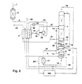
- FIG. 1 A variant of the method according to FIG. 1 is shown in FIG Oxygen and nitrogen can also be obtained from krypton and xenon.
- steps and facilities for krypton / xenon extraction intended. which are outside the rectification system for nitrogen-oxygen separation are located.
- These can be any of the known methods for krypton / xenon extraction from an enriched in these components Serve oxygen fraction, especially the one mentioned above.
- the oxygen fraction 24 is used is withdrawn from the bottom of the low pressure column.
- the purified rinse fraction downstream of the Cleaning stage 17 partially or completely via line 201 to system 202 Krypton / Xenon extraction supplied, preferably in the liquid state.
- it can be fed into an exchange column at a suitable point are used to produce a krypton- and xenon-containing but oxygen-free Mixture is used, or in another column for the pre-enrichment of krypton and / or Xenon.
- the feed point is below the head of the corresponding column.
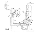
- Intermediate fraction 342 is used as a heating medium which is gaseous from line 330 Intermediate (alternatively: from the head) of the pressure column 6 removed and in Main heat exchanger 4 is heated.
- the warmed heating means 331 is in a compressor 332, for example, compressed to 8 bar and after cooling 333 fed back to the main heat exchanger 4 (line 334). There it will be cooled and finally at least partially condensed. That condensed Heating medium 343 is expanded again into the pressure column, preferably at that point its withdrawal via line 330 or slightly higher.
- At least part of that for the compression of the heated heating means 331 required energy is generated by the work relaxation 336 generated mechanical energy is formed; preferably the Relaxation machine 336 and the compressor 332 mechanically coupled.
- the tapping points are workload to relax intermediate fraction and the heating medium on the same Height, that of the deduction of the oxygenated fraction 13. They could also be at different heights, for example it is possible both at different points above the removal of the oxygen-enriched To order fraction 13. As a result, the feed points also move to Low pressure column and pressure column.
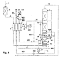
- the method shown schematically in FIG. 4 is used to obtain gaseous oxygen under increased pressure due to internal compression.
- This will liquid oxygen 423 from the low pressure column 7 in a pump 452 to one brought increased pressure of, for example, 9 bar.
- the liquid 453 is under the high pressure supplied to the main heat exchanger 4 and evaporated there warmed up.
- the gaseous pressure product is withdrawn via line 422.
- the heated heating fluid 431 is in one by means of external energy driven compressor 432 compressed to, for example, 20 bar and after After-cooling 433 fed back to the main heat exchanger 4 (line 454). There it is cooled and at least partially condensed.
- the condensed heating fluid 455 is throttled back into the pressure column, preferably in its place Withdrawal via line 430 or slightly higher.
- Part 434 of compressor 432 compressed intermediate fraction 430/431 from the pressure column can for the Extraction of cold can be used by at an intermediate temperature from the Main heat exchanger removed (line 35) and an expansion machine 36 is fed.
- the work-relieved faction is via line 37 downstream of the work-providing relaxation 36 of the low-pressure column 7 at one Intermediate fed.
- you can use the dotted line Line 451 can be returned to the pressure column 6.
- FIGS. 3 and 4 can be obtained using krypton / xenon Figure 2 can be combined.
Landscapes
- Engineering & Computer Science (AREA)
- Physics & Mathematics (AREA)
- Mechanical Engineering (AREA)
- Thermal Sciences (AREA)
- General Engineering & Computer Science (AREA)
- Health & Medical Sciences (AREA)
- Emergency Medicine (AREA)
- Separation By Low-Temperature Treatments (AREA)
- Processing Of Solid Wastes (AREA)
Description
- Figur 1
- eine Ausführungsform mit einer Realisierung der Erfindung bei einem Zweisäulenapparat,
- Figur 2
- eine Ausführungsform der Erfindung mit der Gewinnung von Krypton und/oder Xenon,
- Figur 3
- eine Variante mit abweichender Methode zur Gewinnung von Verfahrenskälte und
- Figur 4
- ein Verfahren mit Gewinnung von Drucksauerstoff mittels Innenverdichtung.
Claims (12)
- Verfahren zur Tieftemperaturzerlegung von Luft, bei dem verdichtete und vorgereinigte Einsatzluft (3, 5) in ein Rektifiziersystem zur Stickstoff-Sauerstoff-Trennung eingeleitet wird, das eine Drucksäule (6) aufweist, wobei mindestens ein Teil der verdichteten und vorgereinigten Einsatzluft der Drucksäule (6) zugespeist (5) wird, eine sauerstoffangereicherte Fraktion (13) der Drucksäule (6) entnommen und einem weiteren Arbeitsschritt (7) innerhalb des Rektifiziersystems zugeleitet (14) wird, die sauerstoffangereicherte Fraktion (13) mindestens einen theoretischen oder praktischen Boden (15) oberhalb der Stelle entnommen wird, an der verdichtete und vorgereinigte Einsatzluft (5) der Drucksäule zugespeist wird, und wobei vom Sumpf der Drucksäule (6) eine Spülfraktion (16) flüssig abgeführt, in flüssigem Zustand einer Reinigungsstufe (17) zugeführt, in der N2O entfernt wird, und als gereinigte Spülfraktion (18) der Reinigungsstufe (17) entnommen wird.
- Verfahren nach Anspruch 1, bei dem N2O in der Reinigungsstufe (17) durch physikalische Adsorption aus der Spülfraktion (16) entfernt wird.
- Verfahren nach Anspruch 1 oder 2, bei dem die Spülfraktion in der Reinigungsstufe durch indirekten Wärmeaustausch verdampft wird, wobei bei der Verdampfung N2O als Feststoff und/oder Flüssigkeit ausfällt.
- Verfahren nach einem der Ansprüche 1 bis 3, bei dem N2O in der Reinigungsstufe durch Gegenstrom-Stoffaustausch aus der Spülfraktion entfernt wird.
- Verfahren nach einem der Ansprüche 1 bis 4, bei dem die gereinigte Spülfraktion (18) mindestens teilweise einem System (202) zur Gewinnung von Krypton und/oder Xenon zugeführt wird.
- Verfahren nach einem der Ansprüche 1 bis 5, bei dem die gesamte Einsatzluft (1, 3, 5), die in dem Rektifiziersystem zerlegt wird. in die Drucksäule (6) eingeleitet wird.
- Verfahren nach einem der Ansprüche 1 bis 6, bei dem der Drucksäule (6) eine Zwischenfraktion (30; 340; 430) mindestens einen theoretischen oder praktischen Boden oberhalb der Stelle entnommen wird, an der verdichtete und vorgereinigte Einsatzluft zugespeist (5) wird, und diese Zwischenfraktion (30, 31, 34, 35; 340, 342, 335; 430, 431, 434, 35) arbeitsleistend entspannt (36; 336) wird.
- Verfahren nach Anspruch 7, bei dem die Zwischenfraktion stromaufwärts der arbeitsleistenden Entspannung (336) in flüssigem Zustand aus der Drucksäule (6) abgezogen (340), im flüssigen Zustand einer Druckerhöhung (341) unterworfen, durch indirekten Wärmeaustausch (4) verdampft und angewärmt wird.
- Verfahren nach einem der Ansprüche 1 bis 8, bei dem ein Produktstrom (423) flüssigem Zustand auf Druck gebracht (452), gegen ein unter hohem Druck stehendes Heizfluid (454) verdampft und als Druckprodukt (422) abgeführt wird, wobei als Heizfluid eine Gasfraktion (430, 431, 454) eingesetzt wird, die der Drucksäule (6) mindestens einen theoretischen oder praktischen Boden oberhalb der Stelle entnommen (430) wird, an der verdichtete und vorgereinigte Einsatzluft zugespeist (5) wird.
- Verfahren nach einem der Ansprüche 1 bis 9, bei dem ein Teil der Sumpfflüssigkeit der Drucksäule verdampft und das dabei entstandene Gas in die Drucksäule zurückgeleitet wird.
- Vorrichtung zur Tieftemperaturzerlegung von Luft mit einem Rektifiziersystem zur Stickstoff-Sauerstoff-Trennung, das mindestens eine Drucksäule (6) aufweist, mit einer Einsatzleitung (1, 3, 5) zur Einleitung von verdichteter und vorgereinigter Einsatzluft in die Drucksäule (6), mit einer Rohsauerstoffleitung (13, 14) für eine sauerstoffangereicherte Fraktion, die einerseits mit der Drucksäule (6) und andererseits mit einer weiteren Vorrichtung (7) innerhalb des dem Rektifiziersystems zur Stickstoff-Sauerstoff-Trennung verbunden ist, mit einer Spülflüssigkeitsleitung (16), die mit dem Sumpf der Drucksäule (6) und mit einer Reinigungseinrichtung (17) zur Entfernung von N2O verbunden ist, und mit einem Stoffaustauschabschnitt (15) im Umfang mindestens eines theoretischen oder praktischen Bodens, der in der Drucksäule (6) zwischen der Rohsauerstoffleitung (13) und dem Sumpf angeordnet ist.
- Vorrichtung nach Anspruch 11, bei der die Drucksäule durch zwei voneinander getrennte Abschnitte realisiert ist, der erste Abschnitt (Vorsäule) mit der Einsatzluftleitung und der Spülflüssigkeitsleitung verbunden ist und mindestens einen Teil des Stoffaustauschabschnitts zwischen Rohsauerstoffleitung und Sumpf der Drucksäule enthält, wobei eine Gasleitung den Kopf des ersten Abschnitts mit dem unteren Bereich des zweiten Abschnitts (Hauptsäule) verbindet und der zweite Abschnitt mit der Rohsauerstoffleitung verbunden ist.
Priority Applications (1)
| Application Number | Priority Date | Filing Date | Title |
|---|---|---|---|
| EP99939452A EP1102954B1 (de) | 1998-08-06 | 1999-08-05 | Verfahren und vorrichtung zur tieftemperaturzerlegung von luft |
Applications Claiming Priority (8)
| Application Number | Priority Date | Filing Date | Title |
|---|---|---|---|
| DE19835474 | 1998-08-06 | ||
| DE19835474 | 1998-08-06 | ||
| DE19852020 | 1998-11-11 | ||
| DE19852020A DE19852020A1 (de) | 1998-08-06 | 1998-11-11 | Verfahren und Vorrichtung zur Tieftemperaturzerlegung von Luft |
| EP98123463 | 1998-11-12 | ||
| EP98123463A EP0978699A1 (de) | 1998-08-06 | 1998-12-11 | Verfahren und Vorrichtung zur Tieftemperaturzerlegung von Luft |
| PCT/EP1999/005678 WO2000008399A1 (de) | 1998-08-06 | 1999-08-05 | Verfahren und vorrichtung zur tieftemperaturzerlegung von luft |
| EP99939452A EP1102954B1 (de) | 1998-08-06 | 1999-08-05 | Verfahren und vorrichtung zur tieftemperaturzerlegung von luft |
Publications (2)
| Publication Number | Publication Date |
|---|---|
| EP1102954A1 EP1102954A1 (de) | 2001-05-30 |
| EP1102954B1 true EP1102954B1 (de) | 2002-11-27 |
Family
ID=27218571
Family Applications (2)
| Application Number | Title | Priority Date | Filing Date |
|---|---|---|---|
| EP98123463A Withdrawn EP0978699A1 (de) | 1998-06-08 | 1998-12-11 | Verfahren und Vorrichtung zur Tieftemperaturzerlegung von Luft |
| EP99939452A Expired - Lifetime EP1102954B1 (de) | 1998-08-06 | 1999-08-05 | Verfahren und vorrichtung zur tieftemperaturzerlegung von luft |
Family Applications Before (1)
| Application Number | Title | Priority Date | Filing Date |
|---|---|---|---|
| EP98123463A Withdrawn EP0978699A1 (de) | 1998-06-08 | 1998-12-11 | Verfahren und Vorrichtung zur Tieftemperaturzerlegung von Luft |
Country Status (9)
| Country | Link |
|---|---|
| US (1) | US6418753B1 (de) |
| EP (2) | EP0978699A1 (de) |
| CN (1) | CN1171065C (de) |
| AT (1) | ATE228637T1 (de) |
| AU (1) | AU5373799A (de) |
| DE (2) | DE19852020A1 (de) |
| ES (1) | ES2188211T3 (de) |
| TW (1) | TW429301B (de) |
| WO (1) | WO2000008399A1 (de) |
Cited By (2)
| Publication number | Priority date | Publication date | Assignee | Title |
|---|---|---|---|---|
| DE102009014556A1 (de) | 2009-03-24 | 2010-09-30 | Linde Aktiengesellschaft | Verfahren zur Beheizung einer Trennkolonne |
| EP2312248A1 (de) | 2009-10-07 | 2011-04-20 | Linde Aktiengesellschaft | Verfahren und Vorrichtung Gewinnung von Drucksauerstoff und Krypton/Xenon |
Families Citing this family (16)
| Publication number | Priority date | Publication date | Assignee | Title |
|---|---|---|---|---|
| US6164089A (en) * | 1999-07-08 | 2000-12-26 | Air Products And Chemicals, Inc. | Method and apparatus for recovering xenon or a mixture of krypton and xenon from air |
| RU2238791C2 (ru) * | 2002-04-09 | 2004-10-27 | Капралов Петр Алексеевич | Устройство получения первичного криптоно-ксенонового концентрата на воздухоразделительных установках |
| DE10228111A1 (de) * | 2002-06-24 | 2004-01-15 | Linde Ag | Luftzerlegungsverfahren und -anlage mit Mischsäule und Krypton-Xenon-Gewinnung |
| US8443625B2 (en) | 2008-08-14 | 2013-05-21 | Praxair Technology, Inc. | Krypton and xenon recovery method |
| DE102008064117A1 (de) | 2008-12-19 | 2009-05-28 | Linde Ag | Verfahren und Vorrichtung zur Tieftemperaturzerlegung von Luft |
| EP2591301B1 (de) * | 2010-07-05 | 2020-09-02 | L'air Liquide, Societe Anonyme Pour L'etude Et L'exploitation Des Procedes Georges Claude | Vorrichtung und verfahren zur lufttrennung durch kryogene destillation |
| CN102767987B (zh) * | 2012-08-15 | 2014-10-29 | 莱芜钢铁集团有限公司 | 一种解决主换热器堵塞的方法 |
| EP2993432A1 (de) * | 2014-09-02 | 2016-03-09 | Linde Aktiengesellschaft | Verfahren zur tieftemperaturzerlegung von luft und luftzerlegungsanlage |
| CN104964514A (zh) * | 2015-07-10 | 2015-10-07 | 开封空分集团有限公司 | 一种氧化亚氮低温回收系统及回收方法 |
| CN105783422A (zh) * | 2016-04-27 | 2016-07-20 | 北京中科瑞奥能源科技股份有限公司 | 利用己二酸尾气生产液态笑气的方法与系统 |
| CN108302899A (zh) * | 2018-03-29 | 2018-07-20 | 浙江新锐空分设备有限公司 | 一种利用液化空气提取贫氪氙产品的空分系统及方法 |
| US10663222B2 (en) * | 2018-04-25 | 2020-05-26 | Praxair Technology, Inc. | System and method for enhanced recovery of argon and oxygen from a nitrogen producing cryogenic air separation unit |
| US12196486B2 (en) * | 2021-07-21 | 2025-01-14 | Air Products And Chemicals, Inc. | Air separation apparatus, adsorber, and method |
| WO2023061621A1 (de) * | 2021-10-12 | 2023-04-20 | Linde Gmbh | Verfahren zur tieftemperaturzerlegung von luft, verfahren zum betreiben eines stahlwerks und luftzerlegungsanlage |
| EP4477980A1 (de) * | 2023-06-15 | 2024-12-18 | Linde GmbH | Verfahren und vorrichtung zur herstellung von luftprodukten aus einer sauerstofffraktion |
| CN119123754B (zh) * | 2024-09-14 | 2025-03-11 | 北京凯隆分析仪器有限公司 | 基于n2o优化分子空分主冷凝器的方法 |
Family Cites Families (7)
| Publication number | Priority date | Publication date | Assignee | Title |
|---|---|---|---|---|
| DE2535489C3 (de) * | 1975-08-08 | 1978-05-24 | Linde Ag, 6200 Wiesbaden | Verfahren und Vorrichtung zur Zerlegung eines tiefsiedenden Gasgemisches |
| DE3322473A1 (de) * | 1983-06-22 | 1985-01-03 | Linde Ag, 6200 Wiesbaden | Verfahren und vorrichtung zur vermeidung einer anreicherung unerwuenschter komponenten in einem fluessigen medium |
| US4732597A (en) * | 1986-04-22 | 1988-03-22 | The United States Of America As Represented By The United States Department Of Energy | Low energy consumption method for separating gaseous mixtures and in particular for medium purity oxygen production |
| US5067976A (en) * | 1991-02-05 | 1991-11-26 | Air Products And Chemicals, Inc. | Cryogenic process for the production of an oxygen-free and methane-free, krypton/xenon product |
| US5313802A (en) * | 1993-02-16 | 1994-05-24 | Air Products And Chemicals, Inc. | Process to produce a krypton/xenon enriched stream directly from the main air distillation column |
| JP3294390B2 (ja) * | 1993-07-26 | 2002-06-24 | 日本エア・リキード株式会社 | 超高純度亜酸化窒素製造方法及び装置 |
| FR2730172B1 (fr) * | 1995-02-07 | 1997-03-21 | Air Liquide | Methode et appareil de surveillance de fonctionnement d'une installation de separation d'air |
-
1998
- 1998-11-11 DE DE19852020A patent/DE19852020A1/de not_active Withdrawn
- 1998-12-11 EP EP98123463A patent/EP0978699A1/de not_active Withdrawn
-
1999
- 1999-08-04 TW TW088113317A patent/TW429301B/zh not_active IP Right Cessation
- 1999-08-05 US US09/762,196 patent/US6418753B1/en not_active Expired - Fee Related
- 1999-08-05 CN CNB998094021A patent/CN1171065C/zh not_active Expired - Fee Related
- 1999-08-05 WO PCT/EP1999/005678 patent/WO2000008399A1/de not_active Ceased
- 1999-08-05 ES ES99939452T patent/ES2188211T3/es not_active Expired - Lifetime
- 1999-08-05 DE DE59903564T patent/DE59903564D1/de not_active Expired - Fee Related
- 1999-08-05 EP EP99939452A patent/EP1102954B1/de not_active Expired - Lifetime
- 1999-08-05 AU AU53737/99A patent/AU5373799A/en not_active Abandoned
- 1999-08-05 AT AT99939452T patent/ATE228637T1/de not_active IP Right Cessation
Cited By (2)
| Publication number | Priority date | Publication date | Assignee | Title |
|---|---|---|---|---|
| DE102009014556A1 (de) | 2009-03-24 | 2010-09-30 | Linde Aktiengesellschaft | Verfahren zur Beheizung einer Trennkolonne |
| EP2312248A1 (de) | 2009-10-07 | 2011-04-20 | Linde Aktiengesellschaft | Verfahren und Vorrichtung Gewinnung von Drucksauerstoff und Krypton/Xenon |
Also Published As
| Publication number | Publication date |
|---|---|
| AU5373799A (en) | 2000-02-28 |
| TW429301B (en) | 2001-04-11 |
| EP0978699A1 (de) | 2000-02-09 |
| EP1102954A1 (de) | 2001-05-30 |
| CN1311850A (zh) | 2001-09-05 |
| DE19852020A1 (de) | 2000-02-10 |
| WO2000008399A1 (de) | 2000-02-17 |
| ATE228637T1 (de) | 2002-12-15 |
| CN1171065C (zh) | 2004-10-13 |
| DE59903564D1 (de) | 2003-01-09 |
| ES2188211T3 (es) | 2003-06-16 |
| US6418753B1 (en) | 2002-07-16 |
Similar Documents
| Publication | Publication Date | Title |
|---|---|---|
| EP1308680B1 (de) | Verfahren und Vorrichtung zur Gewinnung von Krypton und/oder Xenon durch Tieftemperaturzerlegung von Luft | |
| EP1067345B1 (de) | Verfahren und Vorrichtung zur Tieftemperaturzerlegung von Luft | |
| EP0978699A1 (de) | Verfahren und Vorrichtung zur Tieftemperaturzerlegung von Luft | |
| EP0955509B1 (de) | Verfahren und Vorrichtung zur Gewinnung von hochreinem Sauerstoff | |
| EP1284404A1 (de) | Verfahren und Vorrichtung zur Gewinnung eines Druckprodukts durch Tieftemperaturzerlegung von Luft | |
| EP0948730B1 (de) | Verfahren und vorrichtung zur gewinnung von druckstickstoff | |
| DE69030327T2 (de) | Stickstoffherstellungsverfahren | |
| DE10113791A1 (de) | Argongewinnung mit einem Drei-Säulen-System zur Luftzerlegung und einer Rohargonsäule | |
| DE60031256T2 (de) | Vorrichtung mit variabler auslastung und entsprechendes verfahren zur trennung eines einsatzgemisches | |
| DE10013073A1 (de) | Verfahren und Vorrichtung zur Tieftemperaturzerlegung von Luft | |
| DE10013075A1 (de) | Verfahren zur Gewinnung von gasförmigem und flüssigem Stickstoff mit variablem Anteil des Flüssigprodukts | |
| EP1074805B1 (de) | Verfahren und Vorrichtung zur Gewinnung von Sauerstoff unter überatmosphärischem Druck | |
| EP1376037A1 (de) | Luftzerlegungsverfahren und -anlage mit Mischsäule und Krypton-Xenon-Gewinnung | |
| DE10332863A1 (de) | Verfahren und Vorrichtung zur Gewinnung von Krypton und/oder Xenon durch Tieftemperaturzerlegung von Luft | |
| EP1051588B1 (de) | Verfahren und vorrichtung zum verdampfen von flüssigem sauerstoff | |
| DE69314146T2 (de) | Kryogenisches Lufttrennungsverfahren | |
| EP0768503B1 (de) | Dreifachsäulenverfahren zur Tieftemperaturzerlegung von Luft | |
| DE19951521A1 (de) | Verfahren und Vorrichtung zur Gewinnung eines Druckprodukts durch Tieftemperaturzerlegung von Luft | |
| DE69613279T2 (de) | Lufttrennung | |
| EP2551619A1 (de) | Verfahren und Vorrichtung zur Gewinnung von Druckstickstoff und Drucksauerstoff durch Tieftemperaturzerlegung von Luft | |
| DE19855485A1 (de) | Verfahren und Vorrichtung zur Gewinnung eines krypton- und/oder xenonangereicherten Gemischs durch Gegenstrom-Stoffaustausch | |
| EP4065910A1 (de) | Verfahren und anlage zur tieftemperaturzerlegung von luft | |
| EP1387136A1 (de) | Verfahren und Vorrichtung zur Erzeugung von unreinem Sauerstoff durch Tieftemperaturzerlegung von Luft | |
| DE10000017A1 (de) | Verfahren zur Gewinnung von Krypton und/oder Xenon durch Tieftemperaturzerlegung von Luft | |
| DE60019198T2 (de) | Vorrichtung und Verfahren zur Luftzerlegung durch Tieftemperaturrektifikation |
Legal Events
| Date | Code | Title | Description |
|---|---|---|---|
| PUAI | Public reference made under article 153(3) epc to a published international application that has entered the european phase |
Free format text: ORIGINAL CODE: 0009012 |
|
| 17P | Request for examination filed |
Effective date: 20010306 |
|
| AK | Designated contracting states |
Kind code of ref document: A1 Designated state(s): AT BE CH CY DE DK ES FI FR GB GR IE IT LI LU MC NL PT SE |
|
| AX | Request for extension of the european patent |
Free format text: AL;LT;LV;MK;RO;SI |
|
| GRAG | Despatch of communication of intention to grant |
Free format text: ORIGINAL CODE: EPIDOS AGRA |
|
| 17Q | First examination report despatched |
Effective date: 20010919 |
|
| GRAG | Despatch of communication of intention to grant |
Free format text: ORIGINAL CODE: EPIDOS AGRA |
|
| GRAH | Despatch of communication of intention to grant a patent |
Free format text: ORIGINAL CODE: EPIDOS IGRA |
|
| GRAH | Despatch of communication of intention to grant a patent |
Free format text: ORIGINAL CODE: EPIDOS IGRA |
|
| GRAA | (expected) grant |
Free format text: ORIGINAL CODE: 0009210 |
|
| AK | Designated contracting states |
Kind code of ref document: B1 Designated state(s): AT BE CH CY DE DK ES FI FR GB GR IE IT LI LU MC NL PT SE |
|
| PG25 | Lapsed in a contracting state [announced via postgrant information from national office to epo] |
Ref country code: IE Free format text: LAPSE BECAUSE OF FAILURE TO SUBMIT A TRANSLATION OF THE DESCRIPTION OR TO PAY THE FEE WITHIN THE PRESCRIBED TIME-LIMIT Effective date: 20021127 Ref country code: GR Free format text: LAPSE BECAUSE OF FAILURE TO SUBMIT A TRANSLATION OF THE DESCRIPTION OR TO PAY THE FEE WITHIN THE PRESCRIBED TIME-LIMIT Effective date: 20021127 Ref country code: FI Free format text: LAPSE BECAUSE OF FAILURE TO SUBMIT A TRANSLATION OF THE DESCRIPTION OR TO PAY THE FEE WITHIN THE PRESCRIBED TIME-LIMIT Effective date: 20021127 |
|
| REF | Corresponds to: |
Ref document number: 228637 Country of ref document: AT Date of ref document: 20021215 Kind code of ref document: T |
|
| REG | Reference to a national code |
Ref country code: GB Ref legal event code: FG4D Free format text: NOT ENGLISH |
|
| REG | Reference to a national code |
Ref country code: CH Ref legal event code: EP |
|
| REG | Reference to a national code |
Ref country code: IE Ref legal event code: FG4D Free format text: GERMAN |
|
| REF | Corresponds to: |
Ref document number: 59903564 Country of ref document: DE Date of ref document: 20030109 |
|
| PG25 | Lapsed in a contracting state [announced via postgrant information from national office to epo] |
Ref country code: PT Free format text: LAPSE BECAUSE OF FAILURE TO SUBMIT A TRANSLATION OF THE DESCRIPTION OR TO PAY THE FEE WITHIN THE PRESCRIBED TIME-LIMIT Effective date: 20030227 Ref country code: DK Free format text: LAPSE BECAUSE OF FAILURE TO SUBMIT A TRANSLATION OF THE DESCRIPTION OR TO PAY THE FEE WITHIN THE PRESCRIBED TIME-LIMIT Effective date: 20030227 |
|
| GBT | Gb: translation of ep patent filed (gb section 77(6)(a)/1977) |
Effective date: 20030315 |
|
| LTIE | Lt: invalidation of european patent or patent extension |
Effective date: 20021127 |
|
| REG | Reference to a national code |
Ref country code: ES Ref legal event code: FG2A Ref document number: 2188211 Country of ref document: ES Kind code of ref document: T3 |
|
| ET | Fr: translation filed | ||
| REG | Reference to a national code |
Ref country code: IE Ref legal event code: FD4D Ref document number: 1102954E Country of ref document: IE |
|
| PG25 | Lapsed in a contracting state [announced via postgrant information from national office to epo] |
Ref country code: LU Free format text: LAPSE BECAUSE OF NON-PAYMENT OF DUE FEES Effective date: 20030805 Ref country code: CY Free format text: LAPSE BECAUSE OF FAILURE TO SUBMIT A TRANSLATION OF THE DESCRIPTION OR TO PAY THE FEE WITHIN THE PRESCRIBED TIME-LIMIT Effective date: 20030805 |
|
| PG25 | Lapsed in a contracting state [announced via postgrant information from national office to epo] |
Ref country code: MC Free format text: LAPSE BECAUSE OF NON-PAYMENT OF DUE FEES Effective date: 20030831 Ref country code: LI Free format text: LAPSE BECAUSE OF NON-PAYMENT OF DUE FEES Effective date: 20030831 Ref country code: CH Free format text: LAPSE BECAUSE OF NON-PAYMENT OF DUE FEES Effective date: 20030831 Ref country code: BE Free format text: LAPSE BECAUSE OF NON-PAYMENT OF DUE FEES Effective date: 20030831 |
|
| PLBE | No opposition filed within time limit |
Free format text: ORIGINAL CODE: 0009261 |
|
| STAA | Information on the status of an ep patent application or granted ep patent |
Free format text: STATUS: NO OPPOSITION FILED WITHIN TIME LIMIT |
|
| 26N | No opposition filed |
Effective date: 20030828 |
|
| BERE | Be: lapsed |
Owner name: *LINDE A.G. Effective date: 20030831 |
|
| REG | Reference to a national code |
Ref country code: CH Ref legal event code: PL |
|
| PGFP | Annual fee paid to national office [announced via postgrant information from national office to epo] |
Ref country code: NL Payment date: 20040803 Year of fee payment: 6 |
|
| PGFP | Annual fee paid to national office [announced via postgrant information from national office to epo] |
Ref country code: GB Payment date: 20040804 Year of fee payment: 6 |
|
| PGFP | Annual fee paid to national office [announced via postgrant information from national office to epo] |
Ref country code: SE Payment date: 20040806 Year of fee payment: 6 |
|
| PGFP | Annual fee paid to national office [announced via postgrant information from national office to epo] |
Ref country code: FR Payment date: 20040810 Year of fee payment: 6 |
|
| PGFP | Annual fee paid to national office [announced via postgrant information from national office to epo] |
Ref country code: AT Payment date: 20040811 Year of fee payment: 6 |
|
| PGFP | Annual fee paid to national office [announced via postgrant information from national office to epo] |
Ref country code: DE Payment date: 20040812 Year of fee payment: 6 |
|
| PGFP | Annual fee paid to national office [announced via postgrant information from national office to epo] |
Ref country code: ES Payment date: 20040825 Year of fee payment: 6 |
|
| PG25 | Lapsed in a contracting state [announced via postgrant information from national office to epo] |
Ref country code: IT Free format text: LAPSE BECAUSE OF NON-PAYMENT OF DUE FEES Effective date: 20050805 Ref country code: AT Free format text: LAPSE BECAUSE OF NON-PAYMENT OF DUE FEES Effective date: 20050805 |
|
| PG25 | Lapsed in a contracting state [announced via postgrant information from national office to epo] |
Ref country code: SE Free format text: LAPSE BECAUSE OF NON-PAYMENT OF DUE FEES Effective date: 20050806 Ref country code: ES Free format text: LAPSE BECAUSE OF NON-PAYMENT OF DUE FEES Effective date: 20050806 |
|
| PG25 | Lapsed in a contracting state [announced via postgrant information from national office to epo] |
Ref country code: NL Free format text: LAPSE BECAUSE OF NON-PAYMENT OF DUE FEES Effective date: 20060301 Ref country code: DE Free format text: LAPSE BECAUSE OF NON-PAYMENT OF DUE FEES Effective date: 20060301 |
|
| EUG | Se: european patent has lapsed | ||
| GBPC | Gb: european patent ceased through non-payment of renewal fee |
Effective date: 20050805 |
|
| PG25 | Lapsed in a contracting state [announced via postgrant information from national office to epo] |
Ref country code: FR Free format text: LAPSE BECAUSE OF NON-PAYMENT OF DUE FEES Effective date: 20060428 |
|
| NLV4 | Nl: lapsed or anulled due to non-payment of the annual fee |
Effective date: 20060301 |
|
| REG | Reference to a national code |
Ref country code: FR Ref legal event code: ST Effective date: 20060428 |
|
| REG | Reference to a national code |
Ref country code: ES Ref legal event code: FD2A Effective date: 20050806 |