EP1102668B1 - Method for producing a shaped foam body, especially a foam padding element for a vehicle seat - Google Patents
Method for producing a shaped foam body, especially a foam padding element for a vehicle seat Download PDFInfo
- Publication number
- EP1102668B1 EP1102668B1 EP98939652A EP98939652A EP1102668B1 EP 1102668 B1 EP1102668 B1 EP 1102668B1 EP 98939652 A EP98939652 A EP 98939652A EP 98939652 A EP98939652 A EP 98939652A EP 1102668 B1 EP1102668 B1 EP 1102668B1
- Authority
- EP
- European Patent Office
- Prior art keywords
- cover
- foam
- recess
- foaming
- foam body
- Prior art date
- Legal status (The legal status is an assumption and is not a legal conclusion. Google has not performed a legal analysis and makes no representation as to the accuracy of the status listed.)
- Expired - Lifetime
Links
Images


Classifications
-
- B—PERFORMING OPERATIONS; TRANSPORTING
- B29—WORKING OF PLASTICS; WORKING OF SUBSTANCES IN A PLASTIC STATE IN GENERAL
- B29C—SHAPING OR JOINING OF PLASTICS; SHAPING OF MATERIAL IN A PLASTIC STATE, NOT OTHERWISE PROVIDED FOR; AFTER-TREATMENT OF THE SHAPED PRODUCTS, e.g. REPAIRING
- B29C44/00—Shaping by internal pressure generated in the material, e.g. swelling or foaming ; Producing porous or cellular expanded plastics articles
- B29C44/02—Shaping by internal pressure generated in the material, e.g. swelling or foaming ; Producing porous or cellular expanded plastics articles for articles of definite length, i.e. discrete articles
- B29C44/12—Incorporating or moulding on preformed parts, e.g. inserts or reinforcements
- B29C44/1261—Avoiding impregnation of a preformed part
-
- B—PERFORMING OPERATIONS; TRANSPORTING
- B29—WORKING OF PLASTICS; WORKING OF SUBSTANCES IN A PLASTIC STATE IN GENERAL
- B29C—SHAPING OR JOINING OF PLASTICS; SHAPING OF MATERIAL IN A PLASTIC STATE, NOT OTHERWISE PROVIDED FOR; AFTER-TREATMENT OF THE SHAPED PRODUCTS, e.g. REPAIRING
- B29C33/00—Moulds or cores; Details thereof or accessories therefor
- B29C33/12—Moulds or cores; Details thereof or accessories therefor with incorporated means for positioning inserts, e.g. labels
- B29C33/14—Moulds or cores; Details thereof or accessories therefor with incorporated means for positioning inserts, e.g. labels against the mould wall
- B29C33/16—Moulds or cores; Details thereof or accessories therefor with incorporated means for positioning inserts, e.g. labels against the mould wall using magnetic means
-
- B—PERFORMING OPERATIONS; TRANSPORTING
- B29—WORKING OF PLASTICS; WORKING OF SUBSTANCES IN A PLASTIC STATE IN GENERAL
- B29L—INDEXING SCHEME ASSOCIATED WITH SUBCLASS B29C, RELATING TO PARTICULAR ARTICLES
- B29L2031/00—Other particular articles
- B29L2031/727—Fastening elements
- B29L2031/729—Hook and loop-type fasteners
-
- Y—GENERAL TAGGING OF NEW TECHNOLOGICAL DEVELOPMENTS; GENERAL TAGGING OF CROSS-SECTIONAL TECHNOLOGIES SPANNING OVER SEVERAL SECTIONS OF THE IPC; TECHNICAL SUBJECTS COVERED BY FORMER USPC CROSS-REFERENCE ART COLLECTIONS [XRACs] AND DIGESTS
- Y10—TECHNICAL SUBJECTS COVERED BY FORMER USPC
- Y10T—TECHNICAL SUBJECTS COVERED BY FORMER US CLASSIFICATION
- Y10T428/00—Stock material or miscellaneous articles
- Y10T428/24—Structurally defined web or sheet [e.g., overall dimension, etc.]
- Y10T428/24008—Structurally defined web or sheet [e.g., overall dimension, etc.] including fastener for attaching to external surface
- Y10T428/24017—Hook or barb
Abstract
Description
Die Erfindung bezieht sich auf ein Verfahren zum Herstellen eines Schaumkörperteiles,
insbesondere eines Polsterschaumteiles für einen Fahrzeugsitz,
mit den Merkmalen des Oberbegriffes des Patentanspruches 1.The invention relates to a method for producing a foam body part,
in particular an upholstered foam part for a vehicle seat,
with the features of the preamble of
Schaumkörperteile mit eingeschäumten Haftverschlußteilen finden bevorzugt Anwendung als Polsterschaumteile für Sitzelemente, Rückenlehnen oder Kopfstützen, insbesondere bei Fahrzeugsitzen. Die Haftelemente der eingeschäumten Haftverschlußteile dienen hierbei in der Regel dazu, Überzugstoffe, die mit Haftverschlußteilen mit korrespondierenden Haftelementen versehen sind, am betreffenden Polsterschaumteil zu befestigen.Foam body parts with foamed-in adhesive fastener parts are preferred Use as upholstery foam parts for seat elements, backrests or headrests, especially for vehicle seats. The adhesive elements of the foamed-in fastener parts usually serve to cover materials, those with fastener parts with corresponding adhesive elements are provided to be attached to the relevant upholstery foam part.
Um die Funktionsfähigkeit der Haftverschlußteile sicherzustellen, ist es beim Einschäumvorgang wesentlich, daß die Haftelemente mittels der schaumabhaltenden Abdeckung gegen ein Eindringen des Schaummaterials sicher geschützt sind, so daß ein Verkleben der Haftelemente vermieden ist. In bekannter Weise kann zu diesem Zweck so vorgegangen werden, daß der Haftverschlußteil an der Vorderseite, an der die Haftelemente freiliegen, mit einem die Haftelemente vollflächig bedeckenden Deckelement in Form einer Lage aus einer Dichtmasse bedeckt wird, die nach dem Einschäumvorgang zur Freilegung der Haftelemente wieder abziehbar ist. To ensure the functionality of the fastener parts, it is essential during the foaming process that the adhesive elements by means of foam-preventing cover to prevent the foam material from penetrating are securely protected so that sticking of the adhesive elements is avoided. For this purpose, it can be carried out in a known manner that the adhesive fastener part on the front, where the adhesive elements are exposed, with a cover element in the form covering the entire surface of the adhesive elements a layer of a sealing compound is covered after the foaming process is removable to expose the adhesive elements.
Bei einem in der EP 0 612 485 A1 aufgezeigten, bekannten Haftverschlußteil findet hierbei als Dichtmasse ein thermoplastisches Kunststoffmaterial Verwendung, das nach dem Abziehen einschmelzbar und wiederverwendbar ist.In a known adhesive closure part shown in EP 0 612 485 A1 finds a thermoplastic material as a sealing compound Use that can be melted and reused after peeling is.
Trotz Verwendung einer recycelbaren Dichtmasse ist dieses Vorgehen wegen der zusätzlichen Arbeitsschritte für das Aufbringen des Dichtelementes, das Abziehen und die wegen der Wiederverwendung erforderlichen Maßnahmen sehr aufwendig.Despite the use of a recyclable sealant, this procedure is because the additional steps for applying the sealing element, the stripping and the measures required for reuse very complex.
Aus der WO-A-86 03164 ist ein die Haftelemente bedechendes Deckelement bekannt, des mittels einer magnetischen Halteeinrichtung in lösbare Anlage mit der Einschäumform gebracht wird.WO-A-86 03164 describes the adhesive elements Known cover element, by means of a magnetic holding device is brought into detachable system with the foaming mold.
Durch die US-A-5 654 070 ist ein gattungsgemäßes Verfahren zum Einschäumen von Haftverschlußteilen an Schaumkörperteilen bekannt, mit einer Anordnung von Permanentmagneten an der Einschäumform entlang der seitlichen Ränder der Haftverschlußteile. Bei diesem Verfahren sind gesonderte flexible Kunststoffstreifen als seitliche Dichtungsleisten vorgesehen, die an der Seite des Haftverschlußteils angeordnet sind, die die einzelnen Haftelemente aufweisen und die ein magnetisch anziehbares Material in Pulverform enthalten, welches das bekannte Haftverschlußteil mit den an ihm angeordneten Dichtungsleisten in Anlage mit den Permanentmagneten der Einschäumform hält. Aufgrund der erforderlichen paßgenauen Anbringung dieser gesonderten Dichtungsleisten gestaltet sich die Durchführung des bekannten Verfahrens aufwendig und unwirtschaftlich. Hierzu trägt auch mit bei, um eine sichere Lage des Haftverschlußteils in der Einschäur form mit entsprechend befriedigender Dichtleistung zu erreichen, daß einzelne Metallklammern In das Haftverschlußteil einzubringen sind, die dann mit Permanentmagneten in der Einschäumform wechselwirken, die in der Einschäumform unterhalb der Haftelemente angebracht sind. Trotz dieser zusätzlichen Maßnahme hat es sich in der Praxis gezeigt, daß die Abdichtwirkung bei der Realisierung des bekannten Verfahrens nicht zufriedenstellend ist.US-A-5 654 070 is a generic method for foaming known from fastener parts on foam body parts, with an arrangement of permanent magnets along the foam mold the side edges of the fastener parts. Are in this procedure separate flexible plastic strips are provided as side sealing strips, which are arranged on the side of the fastener part, which the individual Have adhesive elements and a magnetically attractable material contained in powder form, which with the well-known adhesive fastener part sealing strips arranged in contact with the permanent magnets the foam shape holds. Due to the required precise fitting this separate sealing strips is the implementation the known method complex and uneconomical. This helps also with to ensure a secure position of the adhesive fastener part in the mono acid form with correspondingly satisfactory sealing performance to achieve that individual Metal clips are to be introduced into the fastener part, which then interact with permanent magnets in the foam form, which in the Foam mold are attached below the adhesive elements. Despite this additional measure, it has been shown in practice that the sealing effect unsatisfactory in the implementation of the known method is.
Ausgehend von diesem Stand der Technik stellt sich die Erfindung die Aufgabe, ein Verfahren aufzuzeigen, das die Herstellung von Schaumkörpertei len mit eingeschäumten Haftverschlußteilen auf besonders sichere Weise ermöglicht, wobei insbesondere die Gefahr vermieden ist, daß in den Bereich der Haftelemente eindringendes Schaummaterial zu einem Verkleben derselben führt.Based on this prior art, the invention has the task to demonstrate a process involving the manufacture of foam body parts len with foamed-in fastener parts in a particularly safe manner enables, in particular the risk is avoided that in the area the foam material penetrating the adhesive elements to glue same leads.
Bei einem Verfahren der eingangs genannten Art ist diese Aufgabe erfindungsgemäß
durch die im kennzeichnenden Teil des Anspruchs 1 aufgeführten Merkmale gelöst.In the case of a method of the type mentioned at the beginning, this object is according to the invention
solved by the features listed in the characterizing part of
Aufgrund dieser erfindungsgemäßen Anordnung ist sichergestellt, daß jedenfalls die den Bereich der Haftelemente umgebenden Ränder der Abdeckung durch die in diesen Randbereichen wirkenden Magnetkräfte in fester, abdichtender Anlage an der Einschäumform gehalten sind, so daß die Abdichtwirkung unmittelbar in den hinsichtlich des Eindringens von Schaummaterial gefährdeten Randbereichen sichergestellt ist.Because of this invention The arrangement ensures that in any case the area of the adhesive elements surrounding edges of the cover by those in these edge areas acting magnetic forces in a firm, sealing system on the foam mold are held so that the sealing effect directly in terms the ingress of foam material endangered edge areas ensured is.
Es hat sich hierbei gezeigt, daß mit der erfindungsgemäßen Ausgestaltung sich deutlich bessere Abdichtergebnisse erhalten lassen als mit den bekannten Lösungen.It has been shown that with the configuration according to the invention significantly better sealing results can be obtained than with the known ones Solutions.
Des weiteren wird sichergestellt, daß durch die Anwendung von aufkaschiertem Vlies oder Filz als Abdeckung eine gute Bindung mit dem Schaummaterial erreicht ist gegenüber der aus der US-A-5 654 070 bekannten Lösung, die auf einem Kunststoffträger mit den Haftelementen, auf der gegenüberliegenden Seite, die frei von jedweder Abdeckung ist, zusätzliche Ankerelemente als Verankerungsmöglichkeit für den Schaum benötigt.It also ensures that the use of laminated Fleece or felt as a cover a good bond with the Foam material is reached from the the US-A-5 654 070 known solution, which is on a plastic carrier with the adhesive elements, on the opposite side, free of any cover is, additional anchor elements as anchoring option for the foam needed.
Vorzugsweise werden die Haftelemente beim Einschäumvorgang in einer in die formgebende Wand der Einschäumform eingearbeiteten Ausnehmung aufgenommen, über deren Randbereich hinaus die Abdeckung mit vorgegebener Randbreite schaumabdichtend übersteht und mit den Randbereichen der Ausnehmung mittels der Halteeinrichtung in Anlage gebracht wird.The adhesive elements are preferably in one in the foaming process the shaping wall of the molded-in recess added, beyond the edge area, the cover with predetermined Withstands edge width foam-sealing and with the edge areas brought into the recess by means of the holding device becomes.
Die ferromagnetische Beschichtung der Abdeckung kann beispielsweise eine Beschichtung aus Polyurethan sein, wie sie unter der Bezeichnung SU-9182 von der Firma Stahl vertrieben wird, die beigemengte Fe-Partikel der Korngrüße < 10µ als ferromagnetisches Material enthält. The ferromagnetic coating of the cover can be, for example, a coating of polyurethane, such as is marketed under the name SU-9182 by Stahl, the added Fe particles with grain size <10µ as ferromagnetic material contains.
Als der Einschäumform zugehöriger Teil der Halteeinrichtung können Permanentmagnete verwendet werden, beispielsweise in Form einer Reihe von Stabmagneten oder von Magnetleisten, die die in der Wand der Einschäumform ausgebildete Ausnehmung umgeben, in welcher die Haftelemente des einzuschäumenden Haftverschlußteiles aufgenommen werden.Permanent magnets can be used as the part of the holding device belonging to the foaming mold can be used, for example in the form of a series of Bar magnets or of magnetic strips, which are in the wall of the foam mold formed recess in which the adhesive elements of the foam to be foamed Adhesive fastener part are included.
Gegenstand der Erfindung ist auch ein in einen Schaumkörperteil einschäumbares
Haftverschlußteil, das die Merkmale des Anspruches 11 aufweist.The invention also relates to a foamable part of a foam body
Adhesive fastener part having the features of
Nachstehend ist die Erfindung anhand der Zeichnung im einzelnen erläutert. Es zeigen:
- Fig. 1
- eine schematisch vereinfacht und endseitig geschnitten gezeichnete perspektivische Ansicht eines Polsterschaumteiles mit eingeschäumtem Haftverschlußteil;
- Fig. 2
- eine der Fig. 1 ähnliche Ansicht eines Polsterschaumteiles mit einem darin vertieft eingeschäumten Haftverschlußteil;
- Fig. 3
- einen in vergrößertem Maßstab gezeichneten Teilschnitt eines in eine Einschäumform eingelegten Haftverschlußteiles;
- Fig. 3A
- einen stark vergrößert gezeichneten Ausschnitt des in Fig. 3 mit A bezeichneten Bereiches;
- Fig. 4
- einen perspektivisch gezeichneten Ausschnitt einer Einschäumform mit eingelegtem Haftverschlußteil;
- Fig. 5
- eine schematisch vereinfacht gezeichnete perspektivische Ansicht eines in eine Einschäumform einlegbaren Formteiles für eine Pfeifeneinschäumung und
- Fig. 6 und 7
- perspektivische Ansichten des Formteiles von Fig. 5 mit an dieses teilweise bzw. vollständig angelegtem Haftverschlußteil.
- Fig. 1
- a schematically simplified and cut end perspective view of an upholstery foam part with foamed adhesive closure part;
- Fig. 2
- one of Figure 1 similar view of an upholstery foam part with a recessed foam fastener part.
- Fig. 3
- a partial section drawn on an enlarged scale of a fastener part inserted into a foaming mold;
- Figure 3A
- a greatly enlarged section of the area designated in Fig. 3 with A;
- Fig. 4
- a perspective drawn section of a foaming mold with inserted adhesive closure part;
- Fig. 5
- a schematically simplified perspective view of a moldable part for a pipe foam and a foam insert
- 6 and 7
- Perspective views of the molded part of Fig. 5 with this partially or completely applied adhesive fastener.
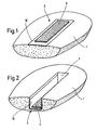
Fig. 1 zeigt einen Teil eines Polsterschaumteiles 1, das an seiner Oberfläche ein
zu dieser bündig eingeschäumtes Haftverschlußteil 3 aufweist. An seiner
Vorder- oder Verhakungsseite weist das Haftverschlußteil 3 Haftelemente 5 auf,
die in bekannter Weise beispielsweise als Schlingen ausgebildet sein können,
wie es in Fig. 3 und 3A ersichtlich ist. Die Haftelemente 5 können auch pilzoder
hakenförmig ausgebildet sein und dienen zur Verhaftung mit entsprechenden,
korrespondierenden Haftelementen eines am Polsterschaumteil 1 anzubringenden
Körpers, beispielsweise eines Überzuges.Fig. 1 shows a part of an
Bei dem Beispiel von Fig. 2 ist das Haftverschlußteil 3 in eine Vertiefung 7 des
Polsterschaumteiles 1 eingeschäumt, so daß die Haftelemente 5 nicht bündig
zur Oberfläche angeordnet sind.In the example of Fig. 2, the
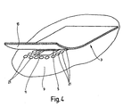
Fig. 3 und 4 verdeutlichen das Einschäumen des Haftverschlußteiles 3 in
bündig zur Oberfläche des Polsterschaumteiles 1 verlaufender Anordnung.
Hierbei wird eine Einschäumform verwendet, deren formgebende Wand 9 im
Bereich des Haftverschlußteiles 3 eine Ausnehmung 11 aufweist, die dem
Flächenbereich der Haftelemente 5 des Haftverschlußteiles 3 angepaßt ist, so
daß bei Anlegen desselben an die Wand 9 der Einschäumform die Haftelemente
5 in der Ausnehmung 11 aufgenommen sind. Wie am deutlichsten aus Fig.
3A ersichtlich ist, sind die Haftelemente 5 mittels einer eine Fesiverklebung
bildenden Haftschicht 13 mit einer auf die Haftschicht 13 aufkaschierten
Abdeckung 15 verbunden. Diese besteht aus einem eine gute Bindung mit dem
Schaummaterial eingehenden Material, beispielsweise einem Vlies oder Filz.
Die Abdeckung 15 erstreckt sich mit ihren äußeren Randbereichen über den
Flächenbereich der Haftelemente 5 und der in der Wand 9 der Einschäumform
ausgebildeten Vertiefung 11 hinaus, wobei die überstehende Randbreite der
Abdeckung 15 so gewählt ist, daß die Randbereiche Permanentmagnete
übergreifen, die in Fig. 3 und 3A als Magnetleisten 17 dargestellt sind. Die
Abdeckung 15 ist mit einer ferromagnetischen Beschichtung versehen,
beispielsweise mit einer Polyurethanbeschichtung mit zugesetzten Fe-Partikeln,
wodurch der Abdeckung 15 ferromagnetische Eigenschaften
verliehen werden, so daß die Randbereiche an den Magnetleisten 17 lösbar
anhaften. Diese Anlage der Randbereiche der Abdeckung 15, um den
Bereich der in der Ausnehmung 11 der Wand 9 aufgenommenen
Haftelemente 5 herum, bildet eine Schaumabdichtung, die beim
Einschäumvorgang einen Zutritt des Schaummaterials zu den
Haftetementen 5 verhindert.3 and 4 illustrate the foaming of the
Die feste Verbindung der Haftelemente 5 mit der Abdeckung 15 kann,
abweichend von der schematisierten Darstellung der Fig. 3A, unmittelbar
über die Ferromagnetika enthaltende Beschichtung erfolgen,
wobei es sich beispielsweise um Kunstharz oder Polyvrethan, insbesondere das Polyurethan SU-9182 der Firma Stahl,
handeln kann. Femer kann eine zur ferromagnetischen Beschichtung
zusätzliche Haftschicht 13 vorgesehen sein, beispielsweise aus einem
feuchtigkeitsvemetzenden Polyurethan (z.B. Tivomelt 9617-11 der Firma
Tivoli) oder aus Kunstharz .The firm connection of the
Fig. 4 verdeutlicht die Verwendung einer Gruppe von Stabmagneten 21
anstelle der in Fig. 3 und 3A gezeigten Magnetleisten 17. Die Stabmagnete
21 sind, wie Fig. 4 zeigt, rings um die Ausnehmung 11 in der Wand 9 der
Einschäumform so angeordnet, daß die Ränder der ferromagnetischen
Abdeckung 15 an der Wand 9 in dichter Anlage gehalten sind.
Fig. 5 bis 7 verdeutlichen den Vorgang der sogenannten Pfeifeneinschäumung,
wobei das Haftverschlußteil 3 in der Vertiefung 7 des betreffenden Polsterschaumteiles
1 eingeschäumt wird. Hierfür findet ein an der Wand 9 der Einschäumform
verankerbares Formteil 23 Anwendung, in dessen Oberfläche die
Vertiefung 11 eingearbeitet ist, in der die Haftelemente 5 des betreffenden
Haftverschlußteiles 3 geschützt aufnehmbar sind. An den Schmalseiten der
Vertiefung 11 befindet sich Magnetleisten 17 zur Anlage der schmalseitigen
Randbereiche der ferromagnetischen Abdeckung 15. Deren langseitige Randbereiche
werden, wie Fig. 6 und 7 zeigen, über abgerundete Ränder 25 des
Formteiles 23 umgelegt, um mit seitlichen Magnetleisten 17 in schaumabdichtende
Anlage zu kommen.4 illustrates the use of a group of
Claims (8)
- Method for producing a foam body part, in particular a padded foam part (1) for a vehicle seat, which part is provided with at least one fastening closure part (3) having fastening elements (5) which are received, covered by a foam-restraining cover (15), in a foaming mould (9) which produces the foam body part, the cover (15) being arranged so as to project beyond the face region of the fastening elements (5) by a predeterminable border width and being moved by means of a holding device into releasable abutment at least with parts of the foaming mould (9), and the cover (15) being provided with ferromagnetic constituents and being used as the first part of the holding device, whose other part associated with the foaming mould (9) is formed by holding elements (17; 21) which are arranged thereon and which generate a magnetic field and by means of which the edges of the cover (15) that project beyond the recess (11) are held during the foaming operation, the cover (15) extending beyond the face region of the fastening elements (5), characterised in that a laminated layer of fleece or felt is used as the cover (15) and is provided with a ferromagnetic coating which extends over the face region of the fastening elements (5).
- Method according to claim 1, characterised in that the fastening elements (5) are received in a recess (11) of the foaming mould (9) and in that the cover (15) is arranged so as to project beyond the recess (11) with the predetermined border width.
- Method according to claim 2, characterised in that polyurethane SU-9182 (Messrs. Stahl) is used as the ferromagnetic coating with the addition of Fe particles.
- Method according to claim 3, characterised in that the cover (15) is connected to the fastening closure part (3) by adhesive bonding (13).
- Method according to any one of claims 1 to 4, characterised in that the cover (15) further has an adhesive base of synthetic resin or polyurethane.
- Method according to any one of claims 1 to 5, characterised in that permanent magnets (17; 21), which co-operate with the edges of the cover (15) that project beyond the recess (11), are used as holding elements which generate the magnetic field and which are associated with the foaming mould (9).
- Method according to claim 6, characterised in that, in order to form foam body parts having fastening closure parts (3) which are arranged embedded therein, a pipe-foaming operation is carried out with shaped parts (23), which can be introduced into the foaming mould (9) and which have the recess (11) and on which the permanent magnets (17) which form part of the holding device are arranged in such a manner that the edges of the cover (15) that project beyond the recess (11) are held thereon during the foaming operation so as to restrain the foam.
- Fastening closure part (3) which can be produced according to the method according to any one of claims 1 to 7 and which can be foamed into a foam body part, having a cover (15) which projects beyond the face region of the fastening elements (5) thereof with a predetermined border width and which forms part of a holding device for the releasable abutment with parts of a foaming mould (9), which serves to produce the foam body part, the cover (15) containing a laminated layer of fleece or felt which is provided with a ferromagnetic coating which extends over the face region of the fastening elements (5).
Applications Claiming Priority (1)
| Application Number | Priority Date | Filing Date | Title |
|---|---|---|---|
| PCT/EP1998/004832 WO2000007792A1 (en) | 1998-08-03 | 1998-08-03 | Method for producing a shaped foam body, especially a foam padding element for a vehicle seat |
Publications (2)
| Publication Number | Publication Date |
|---|---|
| EP1102668A1 EP1102668A1 (en) | 2001-05-30 |
| EP1102668B1 true EP1102668B1 (en) | 2003-09-03 |
Family
ID=8167027
Family Applications (1)
| Application Number | Title | Priority Date | Filing Date |
|---|---|---|---|
| EP98939652A Expired - Lifetime EP1102668B1 (en) | 1998-08-03 | 1998-08-03 | Method for producing a shaped foam body, especially a foam padding element for a vehicle seat |
Country Status (7)
| Country | Link |
|---|---|
| US (1) | US7842368B1 (en) |
| EP (1) | EP1102668B1 (en) |
| JP (1) | JP4414593B2 (en) |
| AT (1) | ATE248696T1 (en) |
| DE (1) | DE59809518D1 (en) |
| ES (1) | ES2206976T3 (en) |
| WO (1) | WO2000007792A1 (en) |
Families Citing this family (13)
| Publication number | Priority date | Publication date | Assignee | Title |
|---|---|---|---|---|
| US7077473B2 (en) | 2003-04-03 | 2006-07-18 | Velcro Industries B.V. | Attaching covers to seat cushions |
| US7303711B2 (en) | 2004-02-24 | 2007-12-04 | Velcro Industries B.V. | Fastener products |
| US7478460B2 (en) | 2004-02-24 | 2009-01-20 | Velcro Industries B.V. | Shear fasteners |
| US7141283B2 (en) | 2004-02-24 | 2006-11-28 | Velcro Industries B.V. | Fasteners |
| US8069537B2 (en) | 2008-05-16 | 2011-12-06 | Velcro Industries B.V. | Fastener products and related methods |
| DE102009053401A1 (en) * | 2009-11-14 | 2011-05-19 | GM Global Technology Operations, Inc., Detroit | Device for partial covering of rear side of backrest, particularly for motor vehicle, has covering element, where device is detachably arranged at upper surface of backrest |
| KR101317484B1 (en) | 2011-04-06 | 2013-10-11 | (주)일광인더스트리 | A manufacturing method of seat pad equipped with the hook of velcro tape |
| USD697726S1 (en) | 2012-09-20 | 2014-01-21 | Steelcase Inc. | Chair |
| TWI548360B (en) * | 2012-10-15 | 2016-09-11 | 台灣百和工業股份有限公司 | Fastening assembly for being embedded in foam and cushion having the fastening assembly |
| JP6342259B2 (en) * | 2014-08-06 | 2018-06-13 | 東洋ゴム工業株式会社 | Seat pad |
| CN105982395A (en) * | 2015-02-26 | 2016-10-05 | 台湾百和工业股份有限公司 | Hook-and-loop fastener for foaming article and foaming article comprising same |
| US10293971B2 (en) | 2016-10-11 | 2019-05-21 | Velcro BVBA | Reclosable paperboard carton |
| US11160334B2 (en) | 2017-08-18 | 2021-11-02 | Velcro Ip Holdings Llc | Fastener element shape |
Family Cites Families (3)
| Publication number | Priority date | Publication date | Assignee | Title |
|---|---|---|---|---|
| IE57148B1 (en) * | 1984-11-20 | 1992-05-06 | Velcro Ind | Separable fasteners as well as method and apparatus for adapting separable fasteners for attachment to other objects |
| US5422156A (en) * | 1993-04-23 | 1995-06-06 | Aplix, Inc. | Fastening member with ferromagnetic attachment strip |
| US5500268A (en) * | 1995-01-31 | 1996-03-19 | Aplix, Inc. | Fastener assembly with magnetic side and end seals and method |
-
1998
- 1998-08-03 WO PCT/EP1998/004832 patent/WO2000007792A1/en active IP Right Grant
- 1998-08-03 ES ES98939652T patent/ES2206976T3/en not_active Expired - Lifetime
- 1998-08-03 US US09/743,710 patent/US7842368B1/en not_active Expired - Fee Related
- 1998-08-03 AT AT98939652T patent/ATE248696T1/en active
- 1998-08-03 EP EP98939652A patent/EP1102668B1/en not_active Expired - Lifetime
- 1998-08-03 DE DE59809518T patent/DE59809518D1/en not_active Expired - Lifetime
- 1998-08-03 JP JP2000563451A patent/JP4414593B2/en not_active Expired - Lifetime
Also Published As
| Publication number | Publication date |
|---|---|
| US7842368B1 (en) | 2010-11-30 |
| EP1102668A1 (en) | 2001-05-30 |
| JP2002522252A (en) | 2002-07-23 |
| ATE248696T1 (en) | 2003-09-15 |
| ES2206976T3 (en) | 2004-05-16 |
| JP4414593B2 (en) | 2010-02-10 |
| DE59809518D1 (en) | 2003-10-09 |
| WO2000007792A1 (en) | 2000-02-17 |
Similar Documents
| Publication | Publication Date | Title |
|---|---|---|
| EP1102668B1 (en) | Method for producing a shaped foam body, especially a foam padding element for a vehicle seat | |
| DE69723272T2 (en) | ADHESIVE TAPE CLOSURE WITH PERMANENT LAYER | |
| DE60127323T2 (en) | Shuttering element formed on a resin article, making this article with such a molded closure element | |
| DE69735362T2 (en) | DEVICE AND METHOD FOR PRODUCING A HEATED SEAT | |
| DE3801431C1 (en) | ||
| DE10129859B4 (en) | Surface fastener | |
| DE19781303B4 (en) | Upholstery element with a Velcro connection to its cover | |
| DE2110382A1 (en) | Vehicle seat, especially for tractors | |
| EP1309258B1 (en) | Fastener part | |
| DE3823584A1 (en) | METHOD FOR PRODUCING A UPHOLSTERY PART | |
| EP1117519B1 (en) | Process for producing foamed articles, especially foamed articles for upholstering car seats, and touch fastening component for use in the process | |
| DE3031290A1 (en) | METHOD FOR ATTACHING A VELCRO TAPE TO A BODY. | |
| DE102010033885A1 (en) | Liner portion used in inner space of motor car, has positioning structure and magnetic device whose in-between portion is subjected to magnetic force attraction, to align positioning structure on positioning structure counter portion | |
| DE4126188C2 (en) | ||
| DE60314350T2 (en) | Infused hook closure | |
| EP1487632A1 (en) | Deformable component, in particular fitting for a motor vehicle and method for producing the same | |
| EP3494827A1 (en) | Adhesive closing part | |
| DE60223327T2 (en) | Related fasteners and method of making a molded plastic article with fastener | |
| DE3903847A1 (en) | Process and apparatus for the foaming and fixing of the adhering or fleeced strip of a touch-and-closed strip into a moulded foam part | |
| EP1039814B1 (en) | Adhesive body | |
| EP1229812A1 (en) | Device for fixing a cover to a foam body, in particular a foam upholstery part for an aircraft or vehicle seat | |
| EP1128944B1 (en) | Method for producing a moulded part, especially a shell member for a car or plane passenger seat | |
| EP1032503A1 (en) | Sealing system with a sealing profile and an adhesive strip | |
| DE102009004321B4 (en) | Zipper element, padding arrangement and vehicle seat | |
| EP0612485B1 (en) | Hook body, embedded into a molded foam part |
Legal Events
| Date | Code | Title | Description |
|---|---|---|---|
| PUAI | Public reference made under article 153(3) epc to a published international application that has entered the european phase |
Free format text: ORIGINAL CODE: 0009012 |
|
| 17P | Request for examination filed |
Effective date: 20001124 |
|
| AK | Designated contracting states |
Kind code of ref document: A1 Designated state(s): AT BE CH DE ES FR GB IT LI LU NL SE |
|
| 17Q | First examination report despatched |
Effective date: 20020227 |
|
| GRAH | Despatch of communication of intention to grant a patent |
Free format text: ORIGINAL CODE: EPIDOS IGRA |
|
| GRAH | Despatch of communication of intention to grant a patent |
Free format text: ORIGINAL CODE: EPIDOS IGRA |
|
| GRAA | (expected) grant |
Free format text: ORIGINAL CODE: 0009210 |
|
| AK | Designated contracting states |
Kind code of ref document: B1 Designated state(s): AT BE CH DE ES FR GB IT LI LU NL SE |
|
| REG | Reference to a national code |
Ref country code: GB Ref legal event code: FG4D Free format text: NOT ENGLISH |
|
| REG | Reference to a national code |
Ref country code: CH Ref legal event code: NV Representative=s name: ISLER & PEDRAZZINI AG Ref country code: CH Ref legal event code: EP |
|
| REF | Corresponds to: |
Ref document number: 59809518 Country of ref document: DE Date of ref document: 20031009 Kind code of ref document: P |
|
| REG | Reference to a national code |
Ref country code: SE Ref legal event code: TRGR |
|
| GBT | Gb: translation of ep patent filed (gb section 77(6)(a)/1977) |
Effective date: 20040103 |
|
| ET | Fr: translation filed | ||
| REG | Reference to a national code |
Ref country code: ES Ref legal event code: FG2A Ref document number: 2206976 Country of ref document: ES Kind code of ref document: T3 |
|
| PLBE | No opposition filed within time limit |
Free format text: ORIGINAL CODE: 0009261 |
|
| STAA | Information on the status of an ep patent application or granted ep patent |
Free format text: STATUS: NO OPPOSITION FILED WITHIN TIME LIMIT |
|
| PG25 | Lapsed in a contracting state [announced via postgrant information from national office to epo] |
Ref country code: LU Free format text: LAPSE BECAUSE OF NON-PAYMENT OF DUE FEES Effective date: 20040803 |
|
| 26N | No opposition filed |
Effective date: 20040604 |
|
| PGFP | Annual fee paid to national office [announced via postgrant information from national office to epo] |
Ref country code: NL Payment date: 20040830 Year of fee payment: 7 |
|
| PG25 | Lapsed in a contracting state [announced via postgrant information from national office to epo] |
Ref country code: LI Free format text: LAPSE BECAUSE OF NON-PAYMENT OF DUE FEES Effective date: 20040831 Ref country code: CH Free format text: LAPSE BECAUSE OF NON-PAYMENT OF DUE FEES Effective date: 20040831 |
|
| REG | Reference to a national code |
Ref country code: CH Ref legal event code: PL |
|
| PG25 | Lapsed in a contracting state [announced via postgrant information from national office to epo] |
Ref country code: NL Free format text: LAPSE BECAUSE OF NON-PAYMENT OF DUE FEES Effective date: 20060301 |
|
| NLV4 | Nl: lapsed or anulled due to non-payment of the annual fee |
Effective date: 20060301 |
|
| PGFP | Annual fee paid to national office [announced via postgrant information from national office to epo] |
Ref country code: GB Payment date: 20140603 Year of fee payment: 17 |
|
| PGFP | Annual fee paid to national office [announced via postgrant information from national office to epo] |
Ref country code: SE Payment date: 20140819 Year of fee payment: 17 Ref country code: ES Payment date: 20140716 Year of fee payment: 17 Ref country code: AT Payment date: 20140808 Year of fee payment: 17 |
|
| PGFP | Annual fee paid to national office [announced via postgrant information from national office to epo] |
Ref country code: IT Payment date: 20140819 Year of fee payment: 17 |
|
| PGFP | Annual fee paid to national office [announced via postgrant information from national office to epo] |
Ref country code: BE Payment date: 20140801 Year of fee payment: 17 |
|
| REG | Reference to a national code |
Ref country code: SE Ref legal event code: EUG |
|
| REG | Reference to a national code |
Ref country code: AT Ref legal event code: MM01 Ref document number: 248696 Country of ref document: AT Kind code of ref document: T Effective date: 20150803 |
|
| GBPC | Gb: european patent ceased through non-payment of renewal fee |
Effective date: 20150803 |
|
| PG25 | Lapsed in a contracting state [announced via postgrant information from national office to epo] |
Ref country code: IT Free format text: LAPSE BECAUSE OF NON-PAYMENT OF DUE FEES Effective date: 20150803 |
|
| PG25 | Lapsed in a contracting state [announced via postgrant information from national office to epo] |
Ref country code: SE Free format text: LAPSE BECAUSE OF NON-PAYMENT OF DUE FEES Effective date: 20150804 Ref country code: AT Free format text: LAPSE BECAUSE OF NON-PAYMENT OF DUE FEES Effective date: 20150803 |
|
| REG | Reference to a national code |
Ref country code: FR Ref legal event code: PLFP Year of fee payment: 19 |
|
| PG25 | Lapsed in a contracting state [announced via postgrant information from national office to epo] |
Ref country code: GB Free format text: LAPSE BECAUSE OF NON-PAYMENT OF DUE FEES Effective date: 20150803 |
|
| REG | Reference to a national code |
Ref country code: ES Ref legal event code: FD2A Effective date: 20160927 |
|
| PG25 | Lapsed in a contracting state [announced via postgrant information from national office to epo] |
Ref country code: ES Free format text: LAPSE BECAUSE OF NON-PAYMENT OF DUE FEES Effective date: 20150804 |
|
| REG | Reference to a national code |
Ref country code: FR Ref legal event code: PLFP Year of fee payment: 20 |
|
| PG25 | Lapsed in a contracting state [announced via postgrant information from national office to epo] |
Ref country code: BE Free format text: LAPSE BECAUSE OF NON-PAYMENT OF DUE FEES Effective date: 20150831 |
|
| PGFP | Annual fee paid to national office [announced via postgrant information from national office to epo] |
Ref country code: DE Payment date: 20170831 Year of fee payment: 20 Ref country code: FR Payment date: 20170710 Year of fee payment: 20 |
|
| REG | Reference to a national code |
Ref country code: DE Ref legal event code: R071 Ref document number: 59809518 Country of ref document: DE |