EP1102628B1 - Method and apparatus for obtaining enhanced production rate of thermal chemical reactions - Google Patents
Method and apparatus for obtaining enhanced production rate of thermal chemical reactions Download PDFInfo
- Publication number
- EP1102628B1 EP1102628B1 EP99938838A EP99938838A EP1102628B1 EP 1102628 B1 EP1102628 B1 EP 1102628B1 EP 99938838 A EP99938838 A EP 99938838A EP 99938838 A EP99938838 A EP 99938838A EP 1102628 B1 EP1102628 B1 EP 1102628B1
- Authority
- EP
- European Patent Office
- Prior art keywords
- recited
- porous insert
- reactor
- reaction chamber
- porous
- Prior art date
- Legal status (The legal status is an assumption and is not a legal conclusion. Google has not performed a legal analysis and makes no representation as to the accuracy of the status listed.)
- Expired - Lifetime
Links
Images

Classifications
-
- B—PERFORMING OPERATIONS; TRANSPORTING
- B01—PHYSICAL OR CHEMICAL PROCESSES OR APPARATUS IN GENERAL
- B01J—CHEMICAL OR PHYSICAL PROCESSES, e.g. CATALYSIS OR COLLOID CHEMISTRY; THEIR RELEVANT APPARATUS
- B01J8/00—Chemical or physical processes in general, conducted in the presence of fluids and solid particles; Apparatus for such processes
- B01J8/02—Chemical or physical processes in general, conducted in the presence of fluids and solid particles; Apparatus for such processes with stationary particles, e.g. in fixed beds
- B01J8/0285—Heating or cooling the reactor
-
- B—PERFORMING OPERATIONS; TRANSPORTING
- B01—PHYSICAL OR CHEMICAL PROCESSES OR APPARATUS IN GENERAL
- B01J—CHEMICAL OR PHYSICAL PROCESSES, e.g. CATALYSIS OR COLLOID CHEMISTRY; THEIR RELEVANT APPARATUS
- B01J12/00—Chemical processes in general for reacting gaseous media with gaseous media; Apparatus specially adapted therefor
- B01J12/007—Chemical processes in general for reacting gaseous media with gaseous media; Apparatus specially adapted therefor in the presence of catalytically active bodies, e.g. porous plates
-
- C—CHEMISTRY; METALLURGY
- C01—INORGANIC CHEMISTRY
- C01B—NON-METALLIC ELEMENTS; COMPOUNDS THEREOF; METALLOIDS OR COMPOUNDS THEREOF NOT COVERED BY SUBCLASS C01C
- C01B3/00—Hydrogen; Gaseous mixtures containing hydrogen; Separation of hydrogen from mixtures containing it; Purification of hydrogen
- C01B3/02—Production of hydrogen or of gaseous mixtures containing a substantial proportion of hydrogen
- C01B3/06—Production of hydrogen or of gaseous mixtures containing a substantial proportion of hydrogen by reaction of inorganic compounds containing electro-positively bound hydrogen, e.g. water, acids, bases, ammonia, with inorganic reducing agents
- C01B3/12—Production of hydrogen or of gaseous mixtures containing a substantial proportion of hydrogen by reaction of inorganic compounds containing electro-positively bound hydrogen, e.g. water, acids, bases, ammonia, with inorganic reducing agents by reaction of water vapour with carbon monoxide
- C01B3/16—Production of hydrogen or of gaseous mixtures containing a substantial proportion of hydrogen by reaction of inorganic compounds containing electro-positively bound hydrogen, e.g. water, acids, bases, ammonia, with inorganic reducing agents by reaction of water vapour with carbon monoxide using catalysts
-
- C—CHEMISTRY; METALLURGY
- C01—INORGANIC CHEMISTRY
- C01B—NON-METALLIC ELEMENTS; COMPOUNDS THEREOF; METALLOIDS OR COMPOUNDS THEREOF NOT COVERED BY SUBCLASS C01C
- C01B3/00—Hydrogen; Gaseous mixtures containing hydrogen; Separation of hydrogen from mixtures containing it; Purification of hydrogen
- C01B3/02—Production of hydrogen or of gaseous mixtures containing a substantial proportion of hydrogen
- C01B3/32—Production of hydrogen or of gaseous mixtures containing a substantial proportion of hydrogen by reaction of gaseous or liquid organic compounds with gasifying agents, e.g. water, carbon dioxide, air
- C01B3/34—Production of hydrogen or of gaseous mixtures containing a substantial proportion of hydrogen by reaction of gaseous or liquid organic compounds with gasifying agents, e.g. water, carbon dioxide, air by reaction of hydrocarbons with gasifying agents
- C01B3/38—Production of hydrogen or of gaseous mixtures containing a substantial proportion of hydrogen by reaction of gaseous or liquid organic compounds with gasifying agents, e.g. water, carbon dioxide, air by reaction of hydrocarbons with gasifying agents using catalysts
- C01B3/384—Production of hydrogen or of gaseous mixtures containing a substantial proportion of hydrogen by reaction of gaseous or liquid organic compounds with gasifying agents, e.g. water, carbon dioxide, air by reaction of hydrocarbons with gasifying agents using catalysts the catalyst being continuously externally heated
-
- F—MECHANICAL ENGINEERING; LIGHTING; HEATING; WEAPONS; BLASTING
- F28—HEAT EXCHANGE IN GENERAL
- F28D—HEAT-EXCHANGE APPARATUS, NOT PROVIDED FOR IN ANOTHER SUBCLASS, IN WHICH THE HEAT-EXCHANGE MEDIA DO NOT COME INTO DIRECT CONTACT
- F28D7/00—Heat-exchange apparatus having stationary tubular conduit assemblies for both heat-exchange media, the media being in contact with different sides of a conduit wall
-
- B—PERFORMING OPERATIONS; TRANSPORTING
- B01—PHYSICAL OR CHEMICAL PROCESSES OR APPARATUS IN GENERAL
- B01J—CHEMICAL OR PHYSICAL PROCESSES, e.g. CATALYSIS OR COLLOID CHEMISTRY; THEIR RELEVANT APPARATUS
- B01J2208/00—Processes carried out in the presence of solid particles; Reactors therefor
- B01J2208/00008—Controlling the process
- B01J2208/00017—Controlling the temperature
- B01J2208/00106—Controlling the temperature by indirect heat exchange
- B01J2208/00309—Controlling the temperature by indirect heat exchange with two or more reactions in heat exchange with each other, such as an endothermic reaction in heat exchange with an exothermic reaction
-
- C—CHEMISTRY; METALLURGY
- C01—INORGANIC CHEMISTRY
- C01B—NON-METALLIC ELEMENTS; COMPOUNDS THEREOF; METALLOIDS OR COMPOUNDS THEREOF NOT COVERED BY SUBCLASS C01C
- C01B2203/00—Integrated processes for the production of hydrogen or synthesis gas
- C01B2203/02—Processes for making hydrogen or synthesis gas
- C01B2203/0205—Processes for making hydrogen or synthesis gas containing a reforming step
- C01B2203/0227—Processes for making hydrogen or synthesis gas containing a reforming step containing a catalytic reforming step
- C01B2203/0233—Processes for making hydrogen or synthesis gas containing a reforming step containing a catalytic reforming step the reforming step being a steam reforming step
-
- C—CHEMISTRY; METALLURGY
- C01—INORGANIC CHEMISTRY
- C01B—NON-METALLIC ELEMENTS; COMPOUNDS THEREOF; METALLOIDS OR COMPOUNDS THEREOF NOT COVERED BY SUBCLASS C01C
- C01B2203/00—Integrated processes for the production of hydrogen or synthesis gas
- C01B2203/02—Processes for making hydrogen or synthesis gas
- C01B2203/0283—Processes for making hydrogen or synthesis gas containing a CO-shift step, i.e. a water gas shift step
-
- C—CHEMISTRY; METALLURGY
- C01—INORGANIC CHEMISTRY
- C01B—NON-METALLIC ELEMENTS; COMPOUNDS THEREOF; METALLOIDS OR COMPOUNDS THEREOF NOT COVERED BY SUBCLASS C01C
- C01B2203/00—Integrated processes for the production of hydrogen or synthesis gas
- C01B2203/04—Integrated processes for the production of hydrogen or synthesis gas containing a purification step for the hydrogen or the synthesis gas
- C01B2203/0465—Composition of the impurity
- C01B2203/0495—Composition of the impurity the impurity being water
-
- C—CHEMISTRY; METALLURGY
- C01—INORGANIC CHEMISTRY
- C01B—NON-METALLIC ELEMENTS; COMPOUNDS THEREOF; METALLOIDS OR COMPOUNDS THEREOF NOT COVERED BY SUBCLASS C01C
- C01B2203/00—Integrated processes for the production of hydrogen or synthesis gas
- C01B2203/08—Methods of heating or cooling
- C01B2203/0805—Methods of heating the process for making hydrogen or synthesis gas
- C01B2203/0833—Heating by indirect heat exchange with hot fluids, other than combustion gases, product gases or non-combustive exothermic reaction product gases
-
- C—CHEMISTRY; METALLURGY
- C01—INORGANIC CHEMISTRY
- C01B—NON-METALLIC ELEMENTS; COMPOUNDS THEREOF; METALLOIDS OR COMPOUNDS THEREOF NOT COVERED BY SUBCLASS C01C
- C01B2203/00—Integrated processes for the production of hydrogen or synthesis gas
- C01B2203/10—Catalysts for performing the hydrogen forming reactions
- C01B2203/1005—Arrangement or shape of catalyst
- C01B2203/1023—Catalysts in the form of a monolith or honeycomb
-
- C—CHEMISTRY; METALLURGY
- C01—INORGANIC CHEMISTRY
- C01B—NON-METALLIC ELEMENTS; COMPOUNDS THEREOF; METALLOIDS OR COMPOUNDS THEREOF NOT COVERED BY SUBCLASS C01C
- C01B2203/00—Integrated processes for the production of hydrogen or synthesis gas
- C01B2203/10—Catalysts for performing the hydrogen forming reactions
- C01B2203/1005—Arrangement or shape of catalyst
- C01B2203/1029—Catalysts in the form of a foam
-
- C—CHEMISTRY; METALLURGY
- C01—INORGANIC CHEMISTRY
- C01B—NON-METALLIC ELEMENTS; COMPOUNDS THEREOF; METALLOIDS OR COMPOUNDS THEREOF NOT COVERED BY SUBCLASS C01C
- C01B2203/00—Integrated processes for the production of hydrogen or synthesis gas
- C01B2203/10—Catalysts for performing the hydrogen forming reactions
- C01B2203/1041—Composition of the catalyst
- C01B2203/1047—Group VIII metal catalysts
- C01B2203/1064—Platinum group metal catalysts
-
- C—CHEMISTRY; METALLURGY
- C01—INORGANIC CHEMISTRY
- C01B—NON-METALLIC ELEMENTS; COMPOUNDS THEREOF; METALLOIDS OR COMPOUNDS THEREOF NOT COVERED BY SUBCLASS C01C
- C01B2203/00—Integrated processes for the production of hydrogen or synthesis gas
- C01B2203/10—Catalysts for performing the hydrogen forming reactions
- C01B2203/1041—Composition of the catalyst
- C01B2203/1082—Composition of support materials
-
- C—CHEMISTRY; METALLURGY
- C01—INORGANIC CHEMISTRY
- C01B—NON-METALLIC ELEMENTS; COMPOUNDS THEREOF; METALLOIDS OR COMPOUNDS THEREOF NOT COVERED BY SUBCLASS C01C
- C01B2203/00—Integrated processes for the production of hydrogen or synthesis gas
- C01B2203/12—Feeding the process for making hydrogen or synthesis gas
- C01B2203/1205—Composition of the feed
- C01B2203/1211—Organic compounds or organic mixtures used in the process for making hydrogen or synthesis gas
- C01B2203/1235—Hydrocarbons
- C01B2203/1241—Natural gas or methane
-
- C—CHEMISTRY; METALLURGY
- C01—INORGANIC CHEMISTRY
- C01B—NON-METALLIC ELEMENTS; COMPOUNDS THEREOF; METALLOIDS OR COMPOUNDS THEREOF NOT COVERED BY SUBCLASS C01C
- C01B2203/00—Integrated processes for the production of hydrogen or synthesis gas
- C01B2203/12—Feeding the process for making hydrogen or synthesis gas
- C01B2203/1205—Composition of the feed
- C01B2203/1211—Organic compounds or organic mixtures used in the process for making hydrogen or synthesis gas
- C01B2203/1235—Hydrocarbons
- C01B2203/1247—Higher hydrocarbons
-
- C—CHEMISTRY; METALLURGY
- C01—INORGANIC CHEMISTRY
- C01B—NON-METALLIC ELEMENTS; COMPOUNDS THEREOF; METALLOIDS OR COMPOUNDS THEREOF NOT COVERED BY SUBCLASS C01C
- C01B2203/00—Integrated processes for the production of hydrogen or synthesis gas
- C01B2203/12—Feeding the process for making hydrogen or synthesis gas
- C01B2203/1288—Evaporation of one or more of the different feed components
-
- C—CHEMISTRY; METALLURGY
- C01—INORGANIC CHEMISTRY
- C01B—NON-METALLIC ELEMENTS; COMPOUNDS THEREOF; METALLOIDS OR COMPOUNDS THEREOF NOT COVERED BY SUBCLASS C01C
- C01B2203/00—Integrated processes for the production of hydrogen or synthesis gas
- C01B2203/16—Controlling the process
- C01B2203/1614—Controlling the temperature
- C01B2203/1619—Measuring the temperature
-
- C—CHEMISTRY; METALLURGY
- C01—INORGANIC CHEMISTRY
- C01B—NON-METALLIC ELEMENTS; COMPOUNDS THEREOF; METALLOIDS OR COMPOUNDS THEREOF NOT COVERED BY SUBCLASS C01C
- C01B2203/00—Integrated processes for the production of hydrogen or synthesis gas
- C01B2203/16—Controlling the process
- C01B2203/1628—Controlling the pressure
- C01B2203/1633—Measuring the pressure
-
- C—CHEMISTRY; METALLURGY
- C01—INORGANIC CHEMISTRY
- C01B—NON-METALLIC ELEMENTS; COMPOUNDS THEREOF; METALLOIDS OR COMPOUNDS THEREOF NOT COVERED BY SUBCLASS C01C
- C01B2203/00—Integrated processes for the production of hydrogen or synthesis gas
- C01B2203/16—Controlling the process
- C01B2203/1642—Controlling the product
- C01B2203/1647—Controlling the amount of the product
- C01B2203/1652—Measuring the amount of product
-
- C—CHEMISTRY; METALLURGY
- C01—INORGANIC CHEMISTRY
- C01B—NON-METALLIC ELEMENTS; COMPOUNDS THEREOF; METALLOIDS OR COMPOUNDS THEREOF NOT COVERED BY SUBCLASS C01C
- C01B2203/00—Integrated processes for the production of hydrogen or synthesis gas
- C01B2203/16—Controlling the process
- C01B2203/1642—Controlling the product
- C01B2203/1671—Controlling the composition of the product
- C01B2203/1676—Measuring the composition of the product
-
- C—CHEMISTRY; METALLURGY
- C01—INORGANIC CHEMISTRY
- C01B—NON-METALLIC ELEMENTS; COMPOUNDS THEREOF; METALLOIDS OR COMPOUNDS THEREOF NOT COVERED BY SUBCLASS C01C
- C01B2203/00—Integrated processes for the production of hydrogen or synthesis gas
- C01B2203/16—Controlling the process
- C01B2203/169—Controlling the feed
-
- Y—GENERAL TAGGING OF NEW TECHNOLOGICAL DEVELOPMENTS; GENERAL TAGGING OF CROSS-SECTIONAL TECHNOLOGIES SPANNING OVER SEVERAL SECTIONS OF THE IPC; TECHNICAL SUBJECTS COVERED BY FORMER USPC CROSS-REFERENCE ART COLLECTIONS [XRACs] AND DIGESTS
- Y02—TECHNOLOGIES OR APPLICATIONS FOR MITIGATION OR ADAPTATION AGAINST CLIMATE CHANGE
- Y02P—CLIMATE CHANGE MITIGATION TECHNOLOGIES IN THE PRODUCTION OR PROCESSING OF GOODS
- Y02P20/00—Technologies relating to chemical industry
- Y02P20/50—Improvements relating to the production of bulk chemicals
- Y02P20/52—Improvements relating to the production of bulk chemicals using catalysts, e.g. selective catalysts
Definitions
- the present invention relates to a method and apparatus for thermal chemical reactions. More specifically, the method and apparatus provide an enhanced reaction rate for the thermal chemical reaction.
- thermal chemical reaction(s) includes exothermic and endothermic chemical reactions.
- Thermal chemical reactions including exothermic and endothermic chemical reactions are well known.
- thermal chemical reactions include but are not limited to Hydrogen and Hydrocarbon conversion reactions including but not limited to steam reforming, water-gas shift reactions and combustion are well known. These reactions are usually carried out in the presence of a catalyst at temperatures up to about 1000 °C . Because the intrinsic kinetics of the thermal chemical reaction are much faster than the heat transfer rate between the reaction vessel and the thermal sink or environment, the rate of product production is limited. Limited production rates may be characterized in terms of residence time which is typically seconds to minutes in convention thermal chemical reaction vessels.
- the water gas shift reaction is conventionally carried out in fixed bed reactors.
- the water gas shift reaction of converting carbon monoxide and water to carbon dioxide and hydrogen suffers from multiple-second residence times (kinetic impediment) when carried out in fixed bed reactors.
- Theoretical kinetics suggests possible residence times on the order of milliseconds.
- the first is a diffusion limitation as reactants diffuse into and out of a catalyst bearing porous pellet and the second is a heat transfer limitation which is a combination of heat transfer parameters (conduction, length) of catalyst supports and overall reactor geometry (shape and size).
- methane steam reforming reactor produces synthesis gas at an average residence time of several seconds and with an effectiveness factor of 0.01 to 0.05 reported by Adris, A., Pruden, B., Lim, C., J. Grace, 1996, On the reported attempts to radically improve the performance of the steam methane reforming reactor, Canadian Journal of Chemical Engineering, 74, 177-186. In typical industrial operation, the methane to steam ratio is run at 3:1 to prevent coke formation.
- a method for obtaining a product at an enhanced production rate for a thermal chemical reaction per reaction chamber volume of a reaction chamber (102 or 104) having an inlet and an outlet for a thermal chemical reaction comprising the steps of:
- a reactor for obtaining an enhanced production rate per reaction chamber volume of a reaction chamber (102 or 104) for a thermal chemical reaction comprising:
- a vessel 100 for thermal chemical reactions the vessel having two chambers 102 and 104 with a wall 106 therebetween. Either of the two chambers 102, 104 may be the reaction chamber. Bulk flow of reactants within the reaction chamber 102 is substantially perpendicular to a cross section plane 108.
- the vessel 100 may have stacked chambers as in FIG. 1 a or nested chambers as in FIG. 1b. The reaction in the reaction chamber may be endothermic or exothermic.
- the rate of production is limited by the rate of heat transfer either to (endothermic) or from (exothermic) the reaction site.
- the reaction chamber has a porous insert (not shown) within the reaction chamber volume wherein the reaction chamber volume with the porous insert has a mean porosity less than 1 and a transport distance no greater than 3 mm, thereby transferring reaction heat at an enhanced heat transfer rate through the porous insert.
- the porous insert may be a powder, a porous monolith (including but not limited to metal or ceramic foam, honeycomb, tube bank, stacked microchannel assembly, and combinations thereof), fibers (e.g. steel wool), or combinations thereof.
- a porous monolith including but not limited to metal or ceramic foam, honeycomb, tube bank, stacked microchannel assembly, and combinations thereof
- fibers e.g. steel wool
- the porous insert may be arranged to provide single or multiple flow passages for reactants through the reaction chamber volume.
- the porous insert may rest on or contact raised features formed on the interior surface(s) of the reaction chamber.
- a preferred porous insert is a porous support with a catalyst material thereon. More preferred is a porous insert with a solution deposited interfacial layer between the porous support and the catalyst material. A more preferred porous insert has a buffer layer between the porous support and the interfacial layer.
- reaction chamber volume has a length parallel to a bulk reactant flow, the length less than or equal to 15.24 cm (6 inches) and has a height less than or equal to 5.08 cm (2 inches).
- the limited length and height provide short distances for the projections thereby permitting faster heat transfer.
- the short length reduces overall pressure drop through the reaction chamber.
- the heat transfer chamber is in thermal contact with the reaction chamber volume, the heat transfer chamber transferring heat at the enhanced heat transfer rate across the wall 106 between the heat transfer chamber and the reaction chamber, thereby obtaining the enhanced production rate per reaction chamber volume for the thermal chemical reaction.
- the interfacial layer is a solution deposited metal oxide.
- the solution deposited metal oxide includes but is not limited to ⁇ Al 2 O 3 , SiO 2 , ZrO 2 , TiO 2, magnesium oxide, vanadium oxide, chromium oxide, manganese oxide, iron oxide, nickel oxide, cobalt oxide, copper oxide, zinc oxide, molybdenum oxide, tin oxide, calcium oxide, aluminum oxide, lanthanum series oxide(s), zeolite(s) and combinations thereof.
- the porous support has a thermal coefficient of expansion different from that of the interfacial layer. Accordingly, for high temperature catalysis (T > 150 °C) a buffer layer is needed to transition between the two coefficients of thermal expansion.
- the buffer layer is a metal oxide that is Al 2 O 3 , TiO 2 and combinations thereof. More specifically, the Al 2 O 3 is ⁇ -Al 2 O 3 , ⁇ -Al 2 O 3 and combinations thereof.
- the structure of the ⁇ -Al 2 O 3 is preferred because TiO 2 is not as a good material as alumina against oxygen diffusion. Therefore, it is expected that resistance against high temperature oxidation can be improved with alumina coated foam.
- the porous substrate 100 is metal foam
- a preferred embodiment has a buffer layer formed of two sub-layers. The first sublayer is ⁇ -Al 2 O 3 for passivating the metal foam and the second layer is TiO 2 for bonding to the interfacial layer.
- Deposition of the buffer layer 102 may be by vapor deposition including but not limited to chemical vapor deposition, physical vapor deposition or combinations thereof. Because the vapor deposition is conducted at high temperatures, polycrystalline phases are formed providing good adhesion of the metal oxide to the metal foam surface.
- the buffer layer 102 may be obtained by solution coating.
- the solution coating has the steps of metal surface functionalization via hydroxide formation, followed by surface hydrolysis of alkoxides to obtain the polycrystalline phases. This solution coating may be preferred as a lower cost method of depositing the buffer layer 102.
- the open cells of a metal foam may range from about 7.9 pores/cm (20 ppi) to about 393.7 pores/cm (1000 ppi) and is preferably about 31.5 pores/cm (80 ppi).
- the catalyst material (when used) is deposited onto the interfacial layer.
- the catalyst material may be any catalyst metal including but not limited to noble metal, transition metal and combinations thereof, or a catalyst metal oxide or transition metal oxide including but not limited to magnesium oxide, titanium oxide, vanadium oxide, chromium oxide, manganese oxide, iron oxide, nickel oxide, cobalt oxide, copper oxide, zinc oxide, zirconium oxide, molybdenum oxide, tin oxide, calcium oxide, aluminum oxide, silicon oxide, lanthanum series oxide(s), zeolite(s) and combinations thereof.
- a catalyst metal oxide or transition metal oxide including but not limited to magnesium oxide, titanium oxide, vanadium oxide, chromium oxide, manganese oxide, iron oxide, nickel oxide, cobalt oxide, copper oxide, zinc oxide, zirconium oxide, molybdenum oxide, tin oxide, calcium oxide, aluminum oxide, silicon oxide, lanthanum series oxide(s), zeolite(s) and combinations thereof.
- the method of making the preferred catalyst has the steps of selecting a porous support, vapor depositing a buffer layer on the porous support, solution depositing a interfacial layer thereon, and depositing a catalyst metal onto the interfacial layer.
- a metal foam is used as the porous support, the metal foam is etched prior to vapor depositing the buffer layer. Etching is preferably with an acid, for example HCl.
- a catalyst layer may be deposited onto the interfacial layer.
- a first porous insert was made with a catalyst material of a pre-reduced and stabilized 5-wt% Ru/ZrO 2 catalyst (1/8-inch extrudates) obtained from Degussa Corporation.
- the catalyst material was ground and sieved to 65 to 100 mesh.
- a second porous insert was made with Ni metal foam with 31.5 pores/cm (80 pores per inch) (ppi) machined to fit in a 7 mm ID quartz tube, ranging from 0.5 to 2.5 cm in length.
- the metal foam was washed in a sonicator with acetone, chloroform, and water successively over 10-minute intervals. It was also etched in a 1 M HCl solution at 60 °C for 30 min.
- the etched metal foam was saturated with a zirconium n-propoxide/1-propanol solution (Aldrich), followed by ambient hydrolysis with water vapor for 72 h, then calcined at 450 °C for 4 h to form the interfacial layer.
- the ZrO 2 -coated metal foam was saturated with a dilute aqueous RuCl 3 solution (RuCl 3 hydrate, Aldrich). The saturation process was repeated several times until the desired Ru loading was achieved.
- the coated metal foam supported Ru catalyst was finally dried at 100 °C in vacuum overnight, followed by calcination at 350 °C for 1 h. Prior to testing, the catalyst was activated with a 10%H 2 /He mixture at 350 °C for at least 1 h.
- a catalytic plug flow reactor (PFR) system was used to test both porous inserts.
- the PFR was configured in a single-zone furnace as the heat transfer chamber.
- the reactor system included a steam generator placed directly prior to the reactor inlet, a PFR housed within the furnace, and a condenser located at the reactor outlet.
- the porous insert was packed in a 7 mm ID quartz tube, which was necked at the center.
- the feed water was fed to the steam generator using a Cole Parmer syringe pump. Carbon monoxide and nitrogen (a diluent) were fed to the system using Matheson mass flow controllers.
- the mixed feed stream flowed through the steam generator before entering the PFR in a downflow fashion.
- the product gases were directed through the condenser and sent to an on-line gas chromatograph, where the product stream was analyzed.
- thermocouples were placed inside the catalytic PFR system. One thermocouple was located above the porous insert. The second thermocouple was placed adjacent to the porous insert outside of the quartz tube to measure the furnace temperature. A pressure gauge at the reactor inlet was used to measure the differential pressure across the porous insert.
- the product gases were analysed immediately upon exit from the reactor with a Microsensor Technology Inc., (MTI) M200 Gas Chromatograph.
- MMI Microsensor Technology Inc.
- the GC analyzes for hydrogen, nitrogen, oxygen, methane, carbon monoxide, air, carbon dioxide, ethane, and ethylene in 75 sec.
- the M200 used a vacuum pump to draw a small sample from the product stream with a 40-sec purge and a 100-millisecond injection time. Water was removed from the gas stream prior to entering the M200.
- Carbon monoxide conversion was calculated based on the moles of material in the inlet and outlet gas stream, as shown in equation 1.
- the selectivity to carbon dioxide (and hydrogen) or methane was calculated in equations 2 and 3, respectively.
- X C O 100 * n C O - i n - n C O - o u t / n C O - i n S
- FIG.'s 2a and 2b show the performance for long and short contact times.
- 25 milliseconds on the Ru-based catalyst was sufficient to convert greater than 98% of the carbon monoxide to carbon dioxide and hydrogen.
- a CO conversion of 99.8 % was measured with a selectivity of 100% to the desired products (CO 2 and H 2 ).
- the equilibrium conversion of CO at 300 °C and a steam to carbon ratio of 3:1 was 99.93%.
- the results with the second porous insert are shown in FIG. 3.
- the CO conversion was less than 10%.
- the measured carbon monoxide conversion reached 94% with a contact time of 50 milliseconds.
- the equilibrium conversion was 94.53% at these conditions.
- the equilibrium CO 2 selectivity was 93.52% at 500 °C.
- the second porous insert of the coated metal foam had a higher activation temperature than the first porous insert of catalyst powder for two reasons.
- the catalyst washcoat had a slightly different composition and structure than the catalyst powders. Independent catalyst tests with powders made from the same washcoat verified the higher required activation temperature.
- the other distinction between the two porous inserts was a reduced weight of active catalyst (approximately 10%) on the coated metal foam.
- Table E2-1 Results for other hydrocarbons are shown in Table E2-1 wherein "time” is residence time.
- Table E2-1 Preliminary hydrocarbon reforming data based on 5%Rh/ ⁇ -Al 2 O 3 catalyst screening tests Hydrocarbon Temperature (C) Time (ms) Conversion % H2 Sel. % Butane 600 25 100 96 Gasoline 800 50 95 ⁇ 95 Iso-octane A 700 25 100 89.5 Kerosene 600 50 95 ⁇ 98 A Catalyst material included a titania buffer layer
- FIG. 5a Further data for an n-butane steam reforming experiment are shown in FIG. 5a .
- Conditions were 650°C at 95 ms residence time with a steam to carbon ratio of 3.58:1.
- the pressure drop increased from negligible to over 48.2 kPa (7 psig) attributed to cracking and spalling of the interfacial and catalyst layers.
- the catalyst was regenerated in air to remove deposited carbon.
- FIG. 5b shows poorer performance. Pressure drop increased to over 48.2 kPa (7 psig) after only 5 operating hours in two days.
Abstract
Description
- The present invention relates to a method and apparatus for thermal chemical reactions. More specifically, the method and apparatus provide an enhanced reaction rate for the thermal chemical reaction.
- As used herein, the term thermal chemical reaction(s) includes exothermic and endothermic chemical reactions.
- Thermal chemical reactions including exothermic and endothermic chemical reactions are well known. Examples of thermal chemical reactions include but are not limited to Hydrogen and Hydrocarbon conversion reactions including but not limited to steam reforming, water-gas shift reactions and combustion are well known. These reactions are usually carried out in the presence of a catalyst at temperatures up to about 1000 °C . Because the intrinsic kinetics of the thermal chemical reaction are much faster than the heat transfer rate between the reaction vessel and the thermal sink or environment, the rate of product production is limited. Limited production rates may be characterized in terms of residence time which is typically seconds to minutes in convention thermal chemical reaction vessels.
- For example, the water gas shift reaction is conventionally carried out in fixed bed reactors. The water gas shift reaction of converting carbon monoxide and water to carbon dioxide and hydrogen suffers from multiple-second residence times (kinetic impediment) when carried out in fixed bed reactors. Theoretical kinetics suggests possible residence times on the order of milliseconds. There are two kinetic retarding aspects to conventional reactors. The first is a diffusion limitation as reactants diffuse into and out of a catalyst bearing porous pellet and the second is a heat transfer limitation which is a combination of heat transfer parameters (conduction, length) of catalyst supports and overall reactor geometry (shape and size). Because the water gas shift reaction is critical to a multi-reactor fuel processing system that supports distributed energy production through the use of a fuel cell, there is a need for a smaller, faster water gas shift reactor.
- Another example is conventional methane steam reforming reactor produces synthesis gas at an average residence time of several seconds and with an effectiveness factor of 0.01 to 0.05 reported by Adris, A., Pruden, B., Lim, C., J. Grace, 1996, On the reported attempts to radically improve the performance of the steam methane reforming reactor, Canadian Journal of Chemical Engineering, 74, 177-186. In typical industrial operation, the methane to steam ratio is run at 3:1 to prevent coke formation.
- Efforts to improve heat transfer between the reaction vessel and the thermal sink have made only modest improvements in product production rate. Thus, there is a need in the art of thermal chemical reactions for a method and apparatus that increases the heat transfer rate between the reaction vessel and the thermal sink and thereby approach the theoretical intrisic kinetic rate of reaction and production.
- In US-A-4795618 heat transfer was promoted by the use of a reaction section and a heat transfer section, both of which are connected by a gas-tight highly heat conductive boundary layer, where both the reaction section and the heat transfer section comprise a porous heat conductive material such as porous sintered metal.
- In WO-A-9632188 similar principles are used, but a second reaction section is used rather than a heat transfer section so that an exothermic reaction in one reaction section can transfer heat to the other reaction section where an endothermic reaction takes place.
- According to one aspect of the present invention there is provided a method for obtaining a product at an enhanced production rate for a thermal chemical reaction per reaction chamber volume of a reaction chamber (102 or 104) having an inlet and an outlet for a thermal chemical reaction, the method comprising the steps of:
- (a) passing a reactant flow through a porous insert within said reaction chamber (102 or 104), wherein the reactant flow substantially completely passes through said porous insert, wherein said reaction chamber volume with said porous insert has a mean porosity of less than 1 and a mass transport distance no greater than 3mm;
- (b) transferring reaction heat through said porous insert, said reaction chamber (102 or 104) having a length parallel to a bulk reactant flow, said length less than or equal to 15cm (6 inches), and with a height less than or equal to 5cm (2 inches); and
- (c) transferring heat through a heat transfer chamber in thermal contact with the reaction chamber volume, said heat transfer chamber comprising an inlet and an outlet and an open space for flow of a heat exchange fluid, and said heat being transferred through a wall between the heat transfer chamber and the reaction chamber (102 or 104).
- According to another aspect of the present invention there is provided a reactor for obtaining an enhanced production rate per reaction chamber volume of a reaction chamber (102 or 104) for a thermal chemical reaction, the reactor comprising:
- (a) a porous insert within said reaction chamber (102 or 104), wherein, during operation, reactant flow substantially completely passes through said porous insert, wherein said reaction chamber (102 or 104) with said porous insert has a mean porosity of less than 1 and a mass transport distance no greater than 3 mm; and
- (b) said reaction chamber volume having an inlet and an outlet, a length parallel to a bulk reactant flow, said length being less than or equal to 15 cm (6 inches), and a height less than or equal to 5 cm (2 inches).
- These features have been found to cooperate with the reaction kinetics in terms of transferring heat at a rate sufficient to avoid substantial impediment of the kinetics. These features are effective for both catalytic and non-catalytic thermal chemical reactions. For catalytic chemical reactions, addition of a catalyst upon the porous insert permits flow of reactants past catalyst sites rather than limiting reactant motion to diffusion as in conventional systems. Thus, according to the present invention, for catalytic thermal chemical reactions, both kinetic impediments are substantially reduced permitting realization of theoretical or near theoretical reaction kinetics. More specifically a water gas shift reactor made according to the present invention has 1/10th to 1/100th the size of conventional processing hardware for the same production output.
- Both the organization and method of operation, together with further advantages and objects thereof, may best be understood by reference to the following description taken in connection with accompanying drawings wherein like reference characters refer to like elements.
-
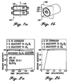
- FIG. 1a is a cross section of a stacked reaction chamber with heat exchanger chamber.
- FIG. 1b is an isometric of a nested reaction chamber with heat exchanger chamber.
- FIG. 2a is a graph of percent selectivity versus residence time for long contact time water gas shift with a powder catalytic porous insert.
- FIG. 2b is a graph of percent selectivity versus residence time for short contact time water gas shift with a powder catalytic porous insert.
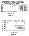
- FIG. 3 is a graph of percent selectivity versus temperature for various residence times for water gas shift with a coated metal foam porous insert.
- FIG. 4 is a graph of methane conversion versus temperature for various residence times for a steam to methane ratio of 2.5:1.
- FIG. 5a is a graph of conversion and selectivity versus time for n-butane steam reforming with a porous insert of a porous substrate with interfacial layer and catalyst material.
- FIG. 5b is a graph of conversion and selectivity versus time for n-butane steam reforming with a regenerated porous insert.
- Referring to FIG.'s 1a and 1b, a
vessel 100 for thermal chemical reactions the vessel having twochambers wall 106 therebetween. Either of the twochambers reaction chamber 102 is substantially perpendicular to across section plane 108. Thevessel 100 may have stacked chambers as in FIG. 1 a or nested chambers as in FIG. 1b. The reaction in the reaction chamber may be endothermic or exothermic. - In a thermal chemical reaction, the rate of production (reaction kinetics) is limited by the rate of heat transfer either to (endothermic) or from (exothermic) the reaction site. In order to obtain an enhanced heat transfer rate and thereby an enhanced production rate, the reaction chamber has a porous insert (not shown) within the reaction chamber volume wherein the reaction chamber volume with the porous insert has a mean porosity less than 1 and a transport distance no greater than 3 mm, thereby transferring reaction heat at an enhanced heat transfer rate through the porous insert.
- The porous insert may be a powder, a porous monolith (including but not limited to metal or ceramic foam, honeycomb, tube bank, stacked microchannel assembly, and combinations thereof), fibers (e.g. steel wool), or combinations thereof. In view of the cost of replacing spent catalyst, for catalytic reactors, it is preferred that the porous insert be removable from the reaction chamber. The porous insert may be arranged to provide single or multiple flow passages for reactants through the reaction chamber volume. The porous insert may rest on or contact raised features formed on the interior surface(s) of the reaction chamber.
- For catalytic thermal chemical reactions, a preferred porous insert is a porous support with a catalyst material thereon. More preferred is a porous insert with a solution deposited interfacial layer between the porous support and the catalyst material. A more preferred porous insert has a buffer layer between the porous support and the interfacial layer.
- In addition, the reaction chamber volume has a length parallel to a bulk reactant flow, the length less than or equal to 15.24 cm (6 inches) and has a height less than or equal to 5.08 cm (2 inches). The limited length and height provide short distances for the projections thereby permitting faster heat transfer. Moreover, the short length reduces overall pressure drop through the reaction chamber.
- The heat transfer chamber is in thermal contact with the reaction chamber volume, the heat transfer chamber transferring heat at the enhanced heat transfer rate across the
wall 106 between the heat transfer chamber and the reaction chamber, thereby obtaining the enhanced production rate per reaction chamber volume for the thermal chemical reaction. - The interfacial layer is a solution deposited metal oxide. The solution deposited metal oxide includes but is not limited to γAl2O3, SiO2, ZrO2, TiO2, magnesium oxide, vanadium oxide, chromium oxide, manganese oxide, iron oxide, nickel oxide, cobalt oxide, copper oxide, zinc oxide, molybdenum oxide, tin oxide, calcium oxide, aluminum oxide, lanthanum series oxide(s), zeolite(s) and combinations thereof. Typically the porous support has a thermal coefficient of expansion different from that of the interfacial layer. Accordingly, for high temperature catalysis (T > 150 °C) a buffer layer is needed to transition between the two coefficients of thermal expansion.
- The buffer layer is a metal oxide that is Al2O3, TiO2 and combinations thereof. More specifically, the Al2O3 is α-Al2O3, γ-Al2O3 and combinations thereof. The structure of the α-Al2O3 is preferred because TiO2 is not as a good material as alumina against oxygen diffusion. Therefore, it is expected that resistance against high temperature oxidation can be improved with alumina coated foam. When the
porous substrate 100 is metal foam, a preferred embodiment has a buffer layer formed of two sub-layers. The first sublayer is α-Al2O3 for passivating the metal foam and the second layer is TiO2 for bonding to the interfacial layer. - Deposition of the
buffer layer 102 may be by vapor deposition including but not limited to chemical vapor deposition, physical vapor deposition or combinations thereof. Because the vapor deposition is conducted at high temperatures, polycrystalline phases are formed providing good adhesion of the metal oxide to the metal foam surface. - Alternatively, the
buffer layer 102 may be obtained by solution coating. The solution coating has the steps of metal surface functionalization via hydroxide formation, followed by surface hydrolysis of alkoxides to obtain the polycrystalline phases. This solution coating may be preferred as a lower cost method of depositing thebuffer layer 102. - Polycrystalline metal oxides resist flaking off under thermal cyclings. The open cells of a metal foam may range from about 7.9 pores/cm (20 ppi) to about 393.7 pores/cm (1000 ppi) and is preferably about 31.5 pores/cm (80 ppi). The catalyst material (when used) is deposited onto the interfacial layer. The catalyst material may be any catalyst metal including but not limited to noble metal, transition metal and combinations thereof, or a catalyst metal oxide or transition metal oxide including but not limited to magnesium oxide, titanium oxide, vanadium oxide, chromium oxide, manganese oxide, iron oxide, nickel oxide, cobalt oxide, copper oxide, zinc oxide, zirconium oxide, molybdenum oxide, tin oxide, calcium oxide, aluminum oxide, silicon oxide, lanthanum series oxide(s), zeolite(s) and combinations thereof.
- The method of making the preferred catalyst has the steps of selecting a porous support, vapor depositing a buffer layer on the porous support, solution depositing a interfacial layer thereon, and depositing a catalyst metal onto the interfacial layer. When a metal foam is used as the porous support, the metal foam is etched prior to vapor depositing the buffer layer. Etching is preferably with an acid, for example HCl. Optionally a catalyst layer may be deposited onto the interfacial layer.
- An experiment was conducted to demonstrate a chemical thermal reactor according to the present invention using the water gas shift reaction.
- A first porous insert was made with a catalyst material of a pre-reduced and stabilized 5-wt% Ru/ZrO2 catalyst (1/8-inch extrudates) obtained from Degussa Corporation. The catalyst material was ground and sieved to 65 to 100 mesh.
- A second porous insert was made with Ni metal foam with 31.5 pores/cm (80 pores per inch) (ppi) machined to fit in a 7 mm ID quartz tube, ranging from 0.5 to 2.5 cm in length. The metal foam was washed in a sonicator with acetone, chloroform, and water successively over 10-minute intervals. It was also etched in a 1 M HCl solution at 60 °C for 30 min. The etched metal foam was saturated with a zirconium n-propoxide/1-propanol solution (Aldrich), followed by ambient hydrolysis with water vapor for 72 h, then calcined at 450 °C for 4 h to form the interfacial layer. The ZrO2 -coated metal foam was saturated with a dilute aqueous RuCl3 solution (RuCl3 hydrate, Aldrich). The saturation process was repeated several times until the desired Ru loading was achieved. The coated metal foam supported Ru catalyst was finally dried at 100 °C in vacuum overnight, followed by calcination at 350 °C for 1 h. Prior to testing, the catalyst was activated with a 10%H2/He mixture at 350 °C for at least 1 h.
- A catalytic plug flow reactor (PFR) system was used to test both porous inserts. The PFR was configured in a single-zone furnace as the heat transfer chamber. The reactor system included a steam generator placed directly prior to the reactor inlet, a PFR housed within the furnace, and a condenser located at the reactor outlet. The porous insert was packed in a 7 mm ID quartz tube, which was necked at the center.
- The feed water was fed to the steam generator using a Cole Parmer syringe pump. Carbon monoxide and nitrogen (a diluent) were fed to the system using Matheson mass flow controllers. The mixed feed stream flowed through the steam generator before entering the PFR in a downflow fashion. The product gases were directed through the condenser and sent to an on-line gas chromatograph, where the product stream was analyzed.
- Two thermocouples were placed inside the catalytic PFR system. One thermocouple was located above the porous insert. The second thermocouple was placed adjacent to the porous insert outside of the quartz tube to measure the furnace temperature. A pressure gauge at the reactor inlet was used to measure the differential pressure across the porous insert.
- The product gases were analysed immediately upon exit from the reactor with a Microsensor Technology Inc., (MTI) M200 Gas Chromatograph. Using a 10-m molecular sieve column (argon carrier gas, 100°C, 234.9 kPa (34.1 psig)) and an 8-m PoraplotU column (helium carrier gas, 65°C 185.3 kPa (26.9 psig)) in parallel, the GC analyzes for hydrogen, nitrogen, oxygen, methane, carbon monoxide, air, carbon dioxide, ethane, and ethylene in 75 sec. The M200 used a vacuum pump to draw a small sample from the product stream with a 40-sec purge and a 100-millisecond injection time. Water was removed from the gas stream prior to entering the M200.
- Carbon monoxide conversion was calculated based on the moles of material in the inlet and outlet gas stream, as shown in
equation 1. The selectivity to carbon dioxide (and hydrogen) or methane was calculated inequations 2 and 3, respectively.


- Using the first porous insert, fine catalyst powders (65 to 100 mesh), the intrinsic reaction kinetics were approximately measured. The contact time varied from 10 milliseconds to 1 sec. FIG.'s 2a and 2b show the performance for long and short contact times. At 300 °C and a steam to carbon ratio of 3:1, 25 milliseconds on the Ru-based catalyst was sufficient to convert greater than 98% of the carbon monoxide to carbon dioxide and hydrogen. At 50 milliseconds, a CO conversion of 99.8 % was measured with a selectivity of 100% to the desired products (CO2 and H2). The equilibrium conversion of CO at 300 °C and a steam to carbon ratio of 3:1 was 99.93%.
- Tests run with longer contact times (> 100 milliseconds) showed the formation of methane, which has an equilibrium selectivity of 22.82%. The equilibrium selectivity line for carbon dioxide and hydrogen is shown on FIG. 2a. As the contact time increased, the formation of methane also increased. A software package, FACT™, was used for all equilibrium calculations.
- The results with the second porous insert (coated metal foam) are shown in FIG. 3. At 300 °C, the CO conversion was less than 10%. However, at 500 °C and a steam to carbon ratio of 3:1, the measured carbon monoxide conversion reached 94% with a contact time of 50 milliseconds. The equilibrium conversion was 94.53% at these conditions. With a contact time as short as 10 milliseconds, the carbon monoxide conversion exceeded 90% and 100% selectivity to carbon dioxide and hydrogen was observed. The equilibrium CO2 selectivity was 93.52% at 500 °C.
- At the contact times of 10, 50, and 100 milliseconds, the measured selectivity remained near 100%, with methane below the detectability limit of the GC. These findings showed that desired non-equilibrium chemistry was exploited in the coated metal foam. Unwanted series and slow parallel reaction pathways, such as the formation of methane, were effectively shut down.
- The second porous insert of the coated metal foam had a higher activation temperature than the first porous insert of catalyst powder for two reasons. First, the catalyst washcoat had a slightly different composition and structure than the catalyst powders. Independent catalyst tests with powders made from the same washcoat verified the higher required activation temperature. The other distinction between the two porous inserts was a reduced weight of active catalyst (approximately 10%) on the coated metal foam.
- An experiment was conducted to demonstrate hydrocarbon steam reforming according to the present invention.
- Using the first porous insert (powder) as in Example 1, methane steam reforming was achieved with 100% conversion at 850°C in 25 milliseconds on a 5%Rh/γ-Al2O3 catalyst (FIG. 4). Using the second porous insert (coated metal foam) as in Example 1, with a 5%Rh/γ-Al2O3 catalyst/interfacial layers on 31.5 pores.cm (80 ppi) stainless steel metal foam reduced the operating temperature by 100°C to achieve the same performance at 750°C.
- No coke formation was observed during any of the millisecond residence time experiments with lower steam to methane ratios (2.5:1).
- Results for other hydrocarbons are shown in Table E2-1 wherein "time" is residence time.
Table E2-1: Preliminary hydrocarbon reforming data based on 5%Rh/γ-Al2O3 catalyst screening tests Hydrocarbon Temperature (C) Time (ms) Conversion % H2 Sel. % Butane 600 25 100 96 Gasoline 800 50 95 ~ 95 Iso-octaneA 700 25 100 89.5 Kerosene 600 50 95 ~ 98 A Catalyst material included a titania buffer layer - Further data for an n-butane steam reforming experiment are shown in FIG. 5a. A porous insert of 31.5 pores/cm (80 ppi) stainless steel with an interfacial layer of alumina and a catalyst material of rhodium (15.6 wt% Rh on 17.1 wt% alumina, balance stainless steel foam, no buffer layer). Conditions were 650°C at 95 ms residence time with a steam to carbon ratio of 3.58:1. The pressure drop increased from negligible to over 48.2 kPa (7 psig) attributed to cracking and spalling of the interfacial and catalyst layers. The catalyst was regenerated in air to remove deposited carbon. FIG. 5b shows poorer performance. Pressure drop increased to over 48.2 kPa (7 psig) after only 5 operating hours in two days.
Claims (45)
- A method for obtaining a product at an enhanced production rate for a thermal chemical reaction per reaction chamber volume of a reaction chamber (102 or 104) having an inlet and an outlet for a thermal chemical reaction, the method comprising the steps of:(a) passing a reactant flow through a porous insert within said reaction chamber (102 or 104), wherein the reactant flow substantially completely passes through said porous insert, wherein said reaction chamber volume with said porous insert has a mean porosity of less than 1 and a mass transport distance no greater than 3mm;(b) transferring reaction heat through said porous insert, said reaction chamber (102 or 104) having a length parallel to a bulk reactant flow, said length less than or equal to 15cm (6 inches), and with a height less than or equal to 5cm (2 inches); and(c) transferring heat through a heat transfer chamber in thermal contact with the reaction chamber volume, said heat transfer chamber comprising an inlet and an outlet and an open space for flow of a heat exchange fluid, and said heat being transferred through a wall between the heat transfer chamber and the reaction chamber (102 or 104).
- The method as recited in claim 1, wherein a catalyst is on the porous insert.
- The method as recited in claim 2, wherein said porous insert has an interfacial layer thereon, and a catalyst metal on the interfacial layer.
- The method as recited in claim 3, wherein said porous insert has a buffer layer between the porous support and the interfacial layer.
- The method as recited in claim 4, wherein said buffer layer is a metal oxide.
- The method as recited in claim 5, wherein said metal oxide is selected from the group consisting of Al2O3, TiO2 and combinations thereof.
- The method as recited in claim 6, wherein said Al2O3 is selected from the group consisting of α -Al2O3, γ -Al2O3, other phases of Al2O3, and combinations thereof.
- The method as recited in any of claims 4 to 7 wherein said buffer layer is vapour-deposited.
- The method as recited in any of claims 4 to 8 wherein said buffer layer comprises a plurality of sublayers.
- The method as recited in any if claim 3 to 9, wherein the interfacial layer is solution-deposited.
- The method as recited in claim 10, wherein said solutions deposited metal oxide is selected from the group consisting of γ - Al2O3, SiO2, ZrO2, TiO2 and combinations thereof.
- The method as recited in any of claims 3 to 11 wherein the interfacial layer comprises a metal oxide.
- The method as recited in any of claims 2 to 12, wherein said catalyst material is a metal selected from the group of noble metal, transition metal and combinations thereof.
- The method as recited in any of the preceding claims, wherein said porous insert comprises a porous ceramic.
- The method as recited in any of the preceding claims wherein the porous insert comprises a porous monolith.
- The method as recited in any of the claims 1-13 wherein the porous insert comprises a metal foam.
- The method as recited in any of the preceding claims wherein the porous insert is in thermal contact with walls of the reaction chamber (102 or 104) and has 8 pores per cm (20 pores per inch) to 400 pores per cm (1000 pores per inch).
- The method as recited in any of the preceding claims, wherein said thermal chemical reaction is a catalytic chemical reaction.
- The method as recited in any of the preceding claims, wherein said thermal chemical reaction is a steam reforming thermal chemical reaction and said reactant flow comprises a hydrocarbon.
- The method as recited in claim 19, wherein said porous insert comprises a porous support with a catalyst material thereon, such that 80% to 100% equilibrium conversion of said hydrocarbon is converted at a residence time of less than about 50 milliseconds.
- The method of claim 20 wherein the residence time is 11 to 50 milliseconds.
- The method of claim 21 wherein the porous insert comprises a metal foam support, an interfacial layer; and wherein the reaction takes place at 600 to 950°C.
- The method of claim 22 wherein the hydrocarbon is selected from the group consisting of butane, gasoline, iso-octant, and kerosene; and wherein hydrogen is produced with a selectivity of 89% to 98%.
- The method as recited in any of claims 1 to 18, wherein said thermal chemical reaction is a water gas shift thermal chemical reaction, and said reactant flow comprises water and carbon monoxide.
- The method as recited in claim 24, wherein said porous insert comprises a porous support with a catalyst material thereon, and said contact time is less than about 100 milliseconds, such that conversion of carbon monoxide is greater than about 50% of equilibrium conversion.
- The method if claim 25 wherein the contact time is between 10 and 100 milliseconds, the conversion is greater than 80%, and the method has a selectivity of at least about 100% of equilibrium selectivity to carbon dioxide.
- The method of claim 26 where the porous insert comprises a metal formed supported Ru catalyst.
- A reactor for obtaining an enhanced production rate per reaction chamber volume of a reaction chamber (102 or 104) for a thermal chemical reaction, the reactor comprising:(a) a porous insert within said reaction chamber (102 or 104), wherein, during operation, reactant flow substantially completely passes through said porous insert, wherein said reaction chamber (102 or 104) with said porous insert has a mean porosity of less than 1 and a mass transport distance no greater than 3 mm; and(b) said reaction chamber volume having an inlet and an outlet, a length parallel to a bulk reactant flow, said length being less than or equal to 15 cm (6 inches), and a height less than or equal to 5 cm (2 inches).
- The reactor as recited in claim 28, wherein a catalyst material is on the porous insert.
- The reactor as recited in claim 29, wherein said porous insert has a solution-deposited interfacial layer between a porous support and the catalyst material.
- The reactor as recited in claim 30, wherein said porous insert has a buffer layer between the porous support and the solution deposited interfacial layer.
- The reactor as recited in claim 31, wherein said buffer layer is a metal oxide.
- The reactor as recited in claim 32, wherein said metal oxide is selected from the group consisting of Al2O3, TiO2 and combination thereof.
- The reactor as recited in claim 33, wherein said Al2O3 is selected from the group consisting of α -Al2O3, γ -Al2O3, other phases of Al2O3, and combinations thereof.
- The reactor as recited in any of claims 31 to 34 wherein said buffer layer us vapour deposited.
- The reactor as recited in any of claims 31 to 35 wherein said buffer layer comprises a plurality of sublayers.
- The reactor as recited in any of claims 30 to 36, wherein the interfacial layer is solution-deposited.
- The reactor as recited in claim 37, wherein said solution-deposited metal oxide is selected from the group consisting of γ -Al2O3, SiO2, ZrO2, TiO2 and combinations thereof.
- The reactor of any of claims 30 to 38 wherein the solution-deposited interfacial layer comprises a metal oxide.
- The reactor as recited in any of claims 29 to 39, wherein said catalyst material is a metal selected from the group of noble metal, transition metal and combinations thereof.
- The reactor as recited in any of claims 28 to 40, wherein the porous insert comprises a porous ceramic.
- The reactor as recited in any of claims 28 to 41 wherein the porous insert comprises a porous monolith.
- The reactor as recited in any of claims 28 to 40 wherein the porous insert comprises a metal foam.
- The reactor as recited in any of claims 28 to 43 wherein the porous insert comprises a metal or ceramic foam and is in thermal contact with walls of the reaction chamber (102 or 104) and has 8 pores per cm (20 pores per inch) to 400 pores per cm (1000 pores per inch).
- A vessel (100) for obtaining an enhanced production rate per reaction chamber volume of a reaction chamber (102 or 104) for a thermal chemical reaction, the vessel (100) comprising:(a) a reactor as recited in any of claims 28-44; and(b) a heat transfer chamber in thermal contact with the reaction chamber volume, said heat transfer chamber having an inlet and outlet, an open space for a flow of a heat exchange fluid, and a wall disposed between the heat transfer chamber and the reaction chamber (102 or 104), such that, during operation, heat transfers across said wall.
Applications Claiming Priority (3)
| Application Number | Priority Date | Filing Date | Title |
|---|---|---|---|
| US123779 | 1993-09-20 | ||
| US09/123,779 US6540975B2 (en) | 1998-07-27 | 1998-07-27 | Method and apparatus for obtaining enhanced production rate of thermal chemical reactions |
| PCT/US1999/017084 WO2000006295A1 (en) | 1998-07-27 | 1999-07-27 | Method and apparatus for obtaining enhanced production rate of thermal chemical reactions |
Publications (2)
| Publication Number | Publication Date |
|---|---|
| EP1102628A1 EP1102628A1 (en) | 2001-05-30 |
| EP1102628B1 true EP1102628B1 (en) | 2006-11-29 |
Family
ID=22410839
Family Applications (1)
| Application Number | Title | Priority Date | Filing Date |
|---|---|---|---|
| EP99938838A Expired - Lifetime EP1102628B1 (en) | 1998-07-27 | 1999-07-27 | Method and apparatus for obtaining enhanced production rate of thermal chemical reactions |
Country Status (8)
| Country | Link |
|---|---|
| US (1) | US6540975B2 (en) |
| EP (1) | EP1102628B1 (en) |
| JP (2) | JP4669126B2 (en) |
| AT (1) | ATE346683T1 (en) |
| CA (2) | CA2338576C (en) |
| DE (1) | DE69934231T2 (en) |
| NO (1) | NO20010375L (en) |
| WO (1) | WO2000006295A1 (en) |
Cited By (8)
| Publication number | Priority date | Publication date | Assignee | Title |
|---|---|---|---|---|
| DE102007027837A1 (en) * | 2007-06-13 | 2008-12-18 | Eads Deutschland Gmbh | Method for producing a metallic microstructure for a microreactor |
| US7935734B2 (en) | 2005-07-08 | 2011-05-03 | Anna Lee Tonkovich | Catalytic reaction process using microchannel technology |
| US8100996B2 (en) | 2008-04-09 | 2012-01-24 | Velocys, Inc. | Process for upgrading a carbonaceous material using microchannel process technology |
| US8580211B2 (en) | 2003-05-16 | 2013-11-12 | Velocys, Inc. | Microchannel with internal fin support for catalyst or sorption medium |
| US8747656B2 (en) | 2008-10-10 | 2014-06-10 | Velocys, Inc. | Process and apparatus employing microchannel process technology |
| US8747805B2 (en) | 2004-02-11 | 2014-06-10 | Velocys, Inc. | Process for conducting an equilibrium limited chemical reaction using microchannel technology |
| US9006298B2 (en) | 2012-08-07 | 2015-04-14 | Velocys, Inc. | Fischer-Tropsch process |
| US9101890B2 (en) | 2005-05-25 | 2015-08-11 | Velocys, Inc. | Support for use in microchannel processing |
Families Citing this family (85)
| Publication number | Priority date | Publication date | Assignee | Title |
|---|---|---|---|---|
| US6117578A (en) * | 1998-04-16 | 2000-09-12 | International Fuel Cells, Llc | Catalyzed wall fuel gas reformer |
| US6440895B1 (en) | 1998-07-27 | 2002-08-27 | Battelle Memorial Institute | Catalyst, method of making, and reactions using the catalyst |
| US6616909B1 (en) * | 1998-07-27 | 2003-09-09 | Battelle Memorial Institute | Method and apparatus for obtaining enhanced production rate of thermal chemical reactions |
| US6946111B2 (en) * | 1999-07-30 | 2005-09-20 | Conocophilips Company | Short contact time catalytic partial oxidation process for recovering sulfur from an H2S containing gas stream |
| US6800269B2 (en) * | 1999-07-30 | 2004-10-05 | Conocophillips Company | Short contact time catalytic sulfur recovery system for removing H2S from a waste gas stream |
| CA2381154C (en) * | 1999-08-17 | 2009-02-03 | Battelle Memorial Institute | Chemical reactor and method for catalytic gas phase reactions |
| US6969506B2 (en) | 1999-08-17 | 2005-11-29 | Battelle Memorial Institute | Methods of conducting simultaneous exothermic and endothermic reactions |
| US6607678B2 (en) | 1999-08-17 | 2003-08-19 | Battelle Memorial Institute | Catalyst and method of steam reforming |
| US6488838B1 (en) | 1999-08-17 | 2002-12-03 | Battelle Memorial Institute | Chemical reactor and method for gas phase reactant catalytic reactions |
| FR2807746B1 (en) * | 2000-04-13 | 2002-12-13 | Air Liquide | METHOD FOR PRODUCING A MIXTURE COMPRISING HYDROGEN AND CO |
| JP4551538B2 (en) * | 2000-07-13 | 2010-09-29 | 株式会社フルヤ金属 | Method for producing steam reforming catalyst |
| ATE342480T1 (en) * | 2000-07-28 | 2006-11-15 | Honda Motor Co Ltd | MULTIPURPOSE MICROCOMPONENT WITH MICROCHANNELS |
| US6730984B1 (en) * | 2000-11-14 | 2004-05-04 | International Business Machines Corporation | Increasing an electrical resistance of a resistor by oxidation or nitridization |
| US7357908B2 (en) * | 2000-12-18 | 2008-04-15 | Conocophillips Company | Apparatus and catalytic partial oxidation process for recovering sulfur from an H2S-containing gas stream |
| US7326397B2 (en) * | 2000-12-18 | 2008-02-05 | Conocophillips Company | Catalytic partial oxidation process for recovering sulfur from an H2S-containing gas stream |
| US6652830B2 (en) | 2001-02-16 | 2003-11-25 | Battelle Memorial Institute | Catalysts reactors and methods of producing hydrogen via the water-gas shift reaction |
| ZA200306075B (en) * | 2001-02-16 | 2004-09-08 | Battelle Memorial Institute | Integrated reactors, methods of making same, and methods of conducting simultaneous exothermic and endothermic reactions. |
| WO2002090248A1 (en) * | 2001-05-07 | 2002-11-14 | Matsushita Electric Industrial Co., Ltd. | Hydrogen purification apparatus |
| US7585472B2 (en) * | 2001-11-07 | 2009-09-08 | Battelle Memorial Institute | Microcombustors, microreformers, and methods involving combusting or reforming fluids |
| US7077643B2 (en) | 2001-11-07 | 2006-07-18 | Battelle Memorial Institute | Microcombustors, microreformers, and methods for combusting and for reforming fluids |
| JP5086516B2 (en) * | 2002-03-11 | 2012-11-28 | バッテル・メモリアル・インスティチュート | Microchannel reactor with temperature control |
| US6746657B2 (en) * | 2002-03-12 | 2004-06-08 | Precision Combustion, Inc. | Method for reduced methanation |
| US6622519B1 (en) * | 2002-08-15 | 2003-09-23 | Velocys, Inc. | Process for cooling a product in a heat exchanger employing microchannels for the flow of refrigerant and product |
| US6969505B2 (en) * | 2002-08-15 | 2005-11-29 | Velocys, Inc. | Process for conducting an equilibrium limited chemical reaction in a single stage process channel |
| US9192929B2 (en) | 2002-08-15 | 2015-11-24 | Velocys, Inc. | Integrated combustion reactor and methods of conducting simultaneous endothermic and exothermic reactions |
| US7250151B2 (en) * | 2002-08-15 | 2007-07-31 | Velocys | Methods of conducting simultaneous endothermic and exothermic reactions |
| US7014835B2 (en) | 2002-08-15 | 2006-03-21 | Velocys, Inc. | Multi-stream microchannel device |
| US6987559B2 (en) | 2002-10-15 | 2006-01-17 | Nikon Corporation | Vibration-attenuation devices having low lateral stiffness, and exposure apparatus comprising same |
| US7404936B2 (en) * | 2002-10-22 | 2008-07-29 | Velocys | Catalysts, in microchannel apparatus, and reactions using same |
| US6652627B1 (en) | 2002-10-30 | 2003-11-25 | Velocys, Inc. | Process for separating a fluid component from a fluid mixture using microchannel process technology |
| US6989134B2 (en) * | 2002-11-27 | 2006-01-24 | Velocys Inc. | Microchannel apparatus, methods of making microchannel apparatus, and processes of conducting unit operations |
| ES2381105T3 (en) * | 2003-02-05 | 2012-05-23 | Haldor Topsoe A/S | Procedure for the treatment of synthesis gas |
| US7326394B2 (en) * | 2003-03-07 | 2008-02-05 | Velocys | Catalysts, methods of making catalysts, and methods of combustion |
| US7405338B2 (en) * | 2003-04-07 | 2008-07-29 | Velocys | Dehydrogenation reactions in narrow reaction chambers and integrated reactors |
| US7294734B2 (en) | 2003-05-02 | 2007-11-13 | Velocys, Inc. | Process for converting a hydrocarbon to an oxygenate or a nitrile |
| WO2004103539A2 (en) * | 2003-05-16 | 2004-12-02 | Velocys Inc. | Process for forming an emulsion using microchannel process technology |
| US7220390B2 (en) * | 2003-05-16 | 2007-05-22 | Velocys, Inc. | Microchannel with internal fin support for catalyst or sorption medium |
| US7485671B2 (en) * | 2003-05-16 | 2009-02-03 | Velocys, Inc. | Process for forming an emulsion using microchannel process technology |
| US7422910B2 (en) * | 2003-10-27 | 2008-09-09 | Velocys | Manifold designs, and flow control in multichannel microchannel devices |
| US7029647B2 (en) * | 2004-01-27 | 2006-04-18 | Velocys, Inc. | Process for producing hydrogen peroxide using microchannel technology |
| US7084180B2 (en) * | 2004-01-28 | 2006-08-01 | Velocys, Inc. | Fischer-tropsch synthesis using microchannel technology and novel catalyst and microchannel reactor |
| US9023900B2 (en) | 2004-01-28 | 2015-05-05 | Velocys, Inc. | Fischer-Tropsch synthesis using microchannel technology and novel catalyst and microchannel reactor |
| US8062623B2 (en) * | 2004-10-15 | 2011-11-22 | Velocys | Stable, catalyzed, high temperature combustion in microchannel, integrated combustion reactors |
| US7874432B2 (en) | 2004-03-23 | 2011-01-25 | Velocys | Protected alloy surfaces in microchannel apparatus and catalysts, alumina supported catalysts, catalyst intermediates, and methods of forming catalysts and microchannel apparatus |
| CA2574113C (en) | 2004-07-23 | 2014-02-18 | Anna Lee Tonkovich | Distillation process using microchannel technology |
| US7305850B2 (en) * | 2004-07-23 | 2007-12-11 | Velocys, Inc. | Distillation process using microchannel technology |
| CA2575165C (en) * | 2004-08-12 | 2014-03-18 | Velocys Inc. | Process for converting ethylene to ethylene oxide using microchannel process technology |
| US7544342B2 (en) * | 2004-08-25 | 2009-06-09 | The Boc Group, Inc. | Hydrogen production process |
| WO2006039568A1 (en) | 2004-10-01 | 2006-04-13 | Velocys Inc. | Multiphase mixing process using microchannel process technology |
| US7566441B2 (en) | 2004-10-15 | 2009-07-28 | Velocys | Methods of conducting catalytic combustion in a multizone reactor, and a method of making a thermally stable catalyst support |
| WO2006065387A1 (en) | 2004-11-03 | 2006-06-22 | Velocys, Inc. | Partial boiling in mini and micro-channels |
| AU2005303765A1 (en) * | 2004-11-12 | 2006-05-18 | Shell Internationale Research Maatschappij B.V. | Tubular reactor with packing |
| CN101128257B (en) * | 2004-11-12 | 2010-10-27 | 万罗赛斯公司 | Process using microchannel technology for conducting alkylation or acylation reaction |
| CA2587546C (en) | 2004-11-16 | 2013-07-09 | Velocys Inc. | Multiphase reaction process using microchannel technology |
| WO2006094190A2 (en) * | 2005-03-02 | 2006-09-08 | Velocys Inc. | Separation process using microchannel technology |
| US20060281187A1 (en) | 2005-06-13 | 2006-12-14 | Rosedale Medical, Inc. | Analyte detection devices and methods with hematocrit/volume correction and feedback control |
| US20070004810A1 (en) * | 2005-06-30 | 2007-01-04 | Yong Wang | Novel catalyst and fischer-tropsch synthesis process using same |
| US8648006B2 (en) * | 2005-10-13 | 2014-02-11 | Velocys, Inc. | Electroless plating in microchannels |
| US7758846B2 (en) * | 2005-12-16 | 2010-07-20 | Battelle Memorial Institute | Methods of producing hydrogen via the water-gas shift reaction over a Pd-Zn catalyst |
| US7226572B1 (en) * | 2006-03-03 | 2007-06-05 | Conocophillips Company | Compact sulfur recovery plant and process |
| EP2004579A2 (en) * | 2006-03-23 | 2008-12-24 | Velocys Inc. | Process for making styrene using microchannel process technology |
| WO2007124409A2 (en) * | 2006-04-20 | 2007-11-01 | Velocys, Inc. | Process for treating and/or forming a non-newtonian fluid using microchannel process technology |
| US20070246106A1 (en) | 2006-04-25 | 2007-10-25 | Velocys Inc. | Flow Distribution Channels To Control Flow in Process Channels |
| US20070298486A1 (en) * | 2006-06-16 | 2007-12-27 | Velocys Inc. | Microchannel Apparatus and Methods Of Conducting Unit Operations With Disrupted Flow |
| US7501111B2 (en) | 2006-08-25 | 2009-03-10 | Conoco Phillips Company | Increased capacity sulfur recovery plant and process for recovering elemental sulfur |
| EP2447339A1 (en) | 2007-01-19 | 2012-05-02 | Velocys Inc. | Process and apparatus for converting natural gas to higher molecular weight hydrocarbons using microchannel process technology |
| US7923592B2 (en) | 2007-02-02 | 2011-04-12 | Velocys, Inc. | Process for making unsaturated hydrocarbons using microchannel process technology |
| DE102007020888A1 (en) * | 2007-05-04 | 2008-11-06 | Micro Systems Engineering Gmbh & Co. Kg | Ceramic substrate material, method of making and using same and antenna or antenna array |
| WO2008143851A1 (en) * | 2007-05-18 | 2008-11-27 | Tribute Creations, Llc | Reactor with differentially distributed catalytic activity |
| DE102007049172A1 (en) * | 2007-10-13 | 2009-04-16 | Micro Systems Engineering Gmbh & Co. Kg | A microreactor and method of making the same and method of making a substrate for a microreactor |
| EP2282828A2 (en) | 2008-04-09 | 2011-02-16 | Velocys, Inc. | Process for converting a carbonaceous material to methane, methanol and/or dimethyl ether using microchannel process technology |
| EP2300447A1 (en) | 2008-07-14 | 2011-03-30 | Basf Se | Process for making ethylene oxide |
| DE102008044946B4 (en) * | 2008-08-29 | 2022-06-15 | Evonik Superabsorber Gmbh | Use of foam bodies in oxidation reactors for the production of unsaturated carboxylic acids |
| DE102008043352A1 (en) * | 2008-10-31 | 2010-05-06 | Micro Systems Engineering Gmbh | Ceramic substrate material, method of making and using same and antenna or antenna array |
| JP2010210118A (en) * | 2009-03-09 | 2010-09-24 | Jamco Corp | Passenger plane mounted steam oven including safety valve for water leakage prevention purposes |
| DE102009012034B4 (en) * | 2009-03-10 | 2011-01-27 | Amocon Gmbh | Process for the purification of a silicon melt |
| EP2260937A1 (en) * | 2009-06-12 | 2010-12-15 | DSM IP Assets B.V. | Device for processing and conditioning of material transported through the device |
| US8524927B2 (en) | 2009-07-13 | 2013-09-03 | Velocys, Inc. | Process for making ethylene oxide using microchannel process technology |
| US8710106B2 (en) * | 2010-07-29 | 2014-04-29 | Precision Combustion, Inc. | Sabatier process and apparatus for controlling exothermic reaction |
| US9950305B2 (en) | 2011-07-26 | 2018-04-24 | Battelle Memorial Institute | Solar thermochemical processing system and method |
| US9676623B2 (en) | 2013-03-14 | 2017-06-13 | Velocys, Inc. | Process and apparatus for conducting simultaneous endothermic and exothermic reactions |
| GB2554618B (en) | 2015-06-12 | 2021-11-10 | Velocys Inc | Synthesis gas conversion process |
| US10710005B2 (en) * | 2017-07-26 | 2020-07-14 | Agency For Science, Technology And Research | Adsorbent material |
| US11358111B2 (en) | 2019-03-20 | 2022-06-14 | Battelle Memorial Institute, Pacific Northwest National Laboratories | Reactor assemblies and methods of performing reactions |
| CN110368945B (en) * | 2019-07-12 | 2022-10-14 | 中国科学院电工研究所 | Method for strengthening catalytic hydrogenation reaction of carbon dioxide |
Family Cites Families (20)
| Publication number | Priority date | Publication date | Assignee | Title |
|---|---|---|---|---|
| US3823743A (en) * | 1970-11-06 | 1974-07-16 | Dunlap Holdings Ltd | Pressure reducing device |
| JPS5765780A (en) * | 1980-10-09 | 1982-04-21 | Toyo Eng Corp | Catalytic gasification |
| DE3435319A1 (en) | 1984-09-26 | 1986-04-03 | Michael 4150 Krefeld Laumen | CATALYTIC STEAM GENERATOR |
| DE3612213A1 (en) * | 1986-04-11 | 1987-10-15 | Basf Ag | TUBE BUNCH REACTOR, THEIR USE IN EXOTHERMAL ORGANIC REACTIONS AND METHOD FOR THE PRODUCTION OF KETONES AND ALDEHYDES WITH THE AID OF THE TUBE BUNCH REACTOR |
| US5011529A (en) * | 1989-03-14 | 1991-04-30 | Corning Incorporated | Cured surfaces and a process of curing |
| AU661877B2 (en) * | 1990-04-03 | 1995-08-10 | Standard Oil Company, The | Endothermic reaction apparatus |
| JP3017568B2 (en) * | 1991-07-24 | 2000-03-13 | 亀山 秀雄 | Methanol reforming method |
| US5303547A (en) * | 1992-04-15 | 1994-04-19 | Amoco Corporation | Emissions control system and method |
| JPH06157004A (en) * | 1992-11-17 | 1994-06-03 | Mitsubishi Heavy Ind Ltd | Apparatus for producing hydrogen by catalytic type steam decomposition method |
| WO1994014008A1 (en) * | 1992-12-17 | 1994-06-23 | Thermatrix Inc. | Method and apparatus for control of fugitive voc emissions |
| US5766458A (en) * | 1993-03-12 | 1998-06-16 | Micropyretics Heaters International, Inc. | Modulated and regenerative ceramic filter with insitu heating element |
| EP0710150A4 (en) * | 1993-07-16 | 1997-12-29 | Thermatrix Inc | Method and afterburner apparatus for control of highly variable flows |
| US5494653A (en) * | 1993-08-27 | 1996-02-27 | Battelle Memorial Institute | Method for hot gas conditioning |
| AU680286B2 (en) * | 1993-09-23 | 1997-07-24 | Shell Internationale Research Maatschappij B.V. | Process for the preparation of carbon monoxide and hydrogen |
| NL1000146C2 (en) * | 1995-04-13 | 1996-10-15 | Gastec Nv | Method for performing a chemical reaction. |
| US5858314A (en) | 1996-04-12 | 1999-01-12 | Ztek Corporation | Thermally enhanced compact reformer |
| JP3675946B2 (en) * | 1996-05-22 | 2005-07-27 | 大阪瓦斯株式会社 | Fuel reformer for fuel cell |
| US5883138A (en) * | 1997-04-25 | 1999-03-16 | Exxon Research And Engineering Company | Rapid injection catalytic partial oxidation process and apparatus for producing synthesis gas (law 562) |
| US6200536B1 (en) * | 1997-06-26 | 2001-03-13 | Battelle Memorial Institute | Active microchannel heat exchanger |
| US6059961A (en) * | 1998-04-27 | 2000-05-09 | Uop Llc | Method to alleviate thermal cycles in moving bed radial flow reactor |
-
1998
- 1998-07-27 US US09/123,779 patent/US6540975B2/en not_active Expired - Lifetime
-
1999
- 1999-07-27 EP EP99938838A patent/EP1102628B1/en not_active Expired - Lifetime
- 1999-07-27 AT AT99938838T patent/ATE346683T1/en not_active IP Right Cessation
- 1999-07-27 WO PCT/US1999/017084 patent/WO2000006295A1/en active IP Right Grant
- 1999-07-27 DE DE69934231T patent/DE69934231T2/en not_active Expired - Lifetime
- 1999-07-27 CA CA002338576A patent/CA2338576C/en not_active Expired - Fee Related
- 1999-07-27 JP JP2000562137A patent/JP4669126B2/en not_active Expired - Fee Related
-
2001
- 2001-01-23 NO NO20010375A patent/NO20010375L/en not_active Application Discontinuation
- 2001-01-24 CA CA2657485A patent/CA2657485C/en not_active Expired - Fee Related
-
2009
- 2009-03-25 JP JP2009074330A patent/JP5111419B2/en not_active Expired - Fee Related
Cited By (9)
| Publication number | Priority date | Publication date | Assignee | Title |
|---|---|---|---|---|
| US8580211B2 (en) | 2003-05-16 | 2013-11-12 | Velocys, Inc. | Microchannel with internal fin support for catalyst or sorption medium |
| US8747805B2 (en) | 2004-02-11 | 2014-06-10 | Velocys, Inc. | Process for conducting an equilibrium limited chemical reaction using microchannel technology |
| US9101890B2 (en) | 2005-05-25 | 2015-08-11 | Velocys, Inc. | Support for use in microchannel processing |
| US7935734B2 (en) | 2005-07-08 | 2011-05-03 | Anna Lee Tonkovich | Catalytic reaction process using microchannel technology |
| DE102007027837A1 (en) * | 2007-06-13 | 2008-12-18 | Eads Deutschland Gmbh | Method for producing a metallic microstructure for a microreactor |
| US8100996B2 (en) | 2008-04-09 | 2012-01-24 | Velocys, Inc. | Process for upgrading a carbonaceous material using microchannel process technology |
| US8747656B2 (en) | 2008-10-10 | 2014-06-10 | Velocys, Inc. | Process and apparatus employing microchannel process technology |
| US9006298B2 (en) | 2012-08-07 | 2015-04-14 | Velocys, Inc. | Fischer-Tropsch process |
| US9359271B2 (en) | 2012-08-07 | 2016-06-07 | Velocys, Inc. | Fischer-Tropsch process |
Also Published As
| Publication number | Publication date |
|---|---|
| CA2338576A1 (en) | 2000-02-10 |
| WO2000006295A1 (en) | 2000-02-10 |
| CA2657485C (en) | 2014-09-16 |
| JP4669126B2 (en) | 2011-04-13 |
| NO20010375D0 (en) | 2001-01-23 |
| JP2009173539A (en) | 2009-08-06 |
| US20020031471A1 (en) | 2002-03-14 |
| CA2657485A1 (en) | 2001-08-02 |
| DE69934231D1 (en) | 2007-01-11 |
| NO20010375L (en) | 2001-03-23 |
| CA2338576C (en) | 2008-04-15 |
| DE69934231T2 (en) | 2007-03-29 |
| US6540975B2 (en) | 2003-04-01 |
| EP1102628A1 (en) | 2001-05-30 |
| JP5111419B2 (en) | 2013-01-09 |
| ATE346683T1 (en) | 2006-12-15 |
| JP2002521192A (en) | 2002-07-16 |
Similar Documents
| Publication | Publication Date | Title |
|---|---|---|
| EP1102628B1 (en) | Method and apparatus for obtaining enhanced production rate of thermal chemical reactions | |
| EP1251949B1 (en) | Method and apparatus for obtaining enhanced production rate of thermal chemical reactions | |
| JP2002521192A5 (en) | ||
| US7682724B2 (en) | Use of metal supported copper catalysts for reforming alcohols | |
| Tonkovich et al. | Microchannel reactors for fuel processing applications. I. Water gas shift reactor | |
| US6936237B2 (en) | Reforming catalysts and methods of alcohol steam reforming | |
| US20040063577A1 (en) | Catalyst for autothermal reforming of hydrocarbons with increased water gas shift activity | |
| US6652830B2 (en) | Catalysts reactors and methods of producing hydrogen via the water-gas shift reaction | |
| US20030116472A1 (en) | Process for catalytic autothermal steam reforming of alcohols | |
| KR20020079612A (en) | A catalyst and process for removing carbon monoxide from a reformate gas | |
| JP2006506309A (en) | Method for producing hydrogen-containing fuel gas for fuel cells and apparatus for this purpose | |
| US20040047787A1 (en) | Process for the selective oxidation of cabon monoxide | |
| MXPA01000943A (en) | Method and apparatus for obtaining enhanced production rate of thermal chemical reactions |
Legal Events
| Date | Code | Title | Description |
|---|---|---|---|
| PUAI | Public reference made under article 153(3) epc to a published international application that has entered the european phase |
Free format text: ORIGINAL CODE: 0009012 |
|
| 17P | Request for examination filed |
Effective date: 20010208 |
|
| AK | Designated contracting states |
Kind code of ref document: A1 Designated state(s): AT BE CH CY DE DK ES FI FR GB GR IE IT LI LU MC NL PT SE |
|
| 17Q | First examination report despatched |
Effective date: 20021209 |
|
| GRAP | Despatch of communication of intention to grant a patent |
Free format text: ORIGINAL CODE: EPIDOSNIGR1 |
|
| GRAS | Grant fee paid |
Free format text: ORIGINAL CODE: EPIDOSNIGR3 |
|
| GRAA | (expected) grant |
Free format text: ORIGINAL CODE: 0009210 |
|
| AK | Designated contracting states |
Kind code of ref document: B1 Designated state(s): AT BE CH CY DE DK ES FI FR GB GR IE IT LI LU MC NL PT SE |
|
| PG25 | Lapsed in a contracting state [announced via postgrant information from national office to epo] |
Ref country code: NL Free format text: LAPSE BECAUSE OF FAILURE TO SUBMIT A TRANSLATION OF THE DESCRIPTION OR TO PAY THE FEE WITHIN THE PRESCRIBED TIME-LIMIT Effective date: 20061129 Ref country code: LI Free format text: LAPSE BECAUSE OF FAILURE TO SUBMIT A TRANSLATION OF THE DESCRIPTION OR TO PAY THE FEE WITHIN THE PRESCRIBED TIME-LIMIT Effective date: 20061129 Ref country code: IT Free format text: LAPSE BECAUSE OF FAILURE TO SUBMIT A TRANSLATION OF THE DESCRIPTION OR TO PAY THE FEE WITHIN THE PRE;WARNING: LAPSES OF ITALIAN PATENTS WITH EFFECTIVE DATE BEFORE 2007 MAY HAVE OCCURRED AT ANY TIME BEFORE 2007. THE CORRECT EFFECTIVE DATE MAY BE DIFFERENT FROM THE ONE RECORDED.SCRIBED TIME-LIMIT Effective date: 20061129 Ref country code: FI Free format text: LAPSE BECAUSE OF FAILURE TO SUBMIT A TRANSLATION OF THE DESCRIPTION OR TO PAY THE FEE WITHIN THE PRESCRIBED TIME-LIMIT Effective date: 20061129 Ref country code: CH Free format text: LAPSE BECAUSE OF FAILURE TO SUBMIT A TRANSLATION OF THE DESCRIPTION OR TO PAY THE FEE WITHIN THE PRESCRIBED TIME-LIMIT Effective date: 20061129 Ref country code: BE Free format text: LAPSE BECAUSE OF FAILURE TO SUBMIT A TRANSLATION OF THE DESCRIPTION OR TO PAY THE FEE WITHIN THE PRESCRIBED TIME-LIMIT Effective date: 20061129 Ref country code: AT Free format text: LAPSE BECAUSE OF FAILURE TO SUBMIT A TRANSLATION OF THE DESCRIPTION OR TO PAY THE FEE WITHIN THE PRESCRIBED TIME-LIMIT Effective date: 20061129 |
|
| REG | Reference to a national code |
Ref country code: GB Ref legal event code: FG4D |
|
| REG | Reference to a national code |
Ref country code: IE Ref legal event code: FG4D Ref country code: CH Ref legal event code: EP |
|
| REG | Reference to a national code |
Ref country code: IE Ref legal event code: FG4D |
|
| REF | Corresponds to: |
Ref document number: 69934231 Country of ref document: DE Date of ref document: 20070111 Kind code of ref document: P |
|
| PG25 | Lapsed in a contracting state [announced via postgrant information from national office to epo] |
Ref country code: SE Free format text: LAPSE BECAUSE OF FAILURE TO SUBMIT A TRANSLATION OF THE DESCRIPTION OR TO PAY THE FEE WITHIN THE PRESCRIBED TIME-LIMIT Effective date: 20070228 Ref country code: DK Free format text: LAPSE BECAUSE OF FAILURE TO SUBMIT A TRANSLATION OF THE DESCRIPTION OR TO PAY THE FEE WITHIN THE PRESCRIBED TIME-LIMIT Effective date: 20070228 |
|
| PG25 | Lapsed in a contracting state [announced via postgrant information from national office to epo] |
Ref country code: ES Free format text: LAPSE BECAUSE OF FAILURE TO SUBMIT A TRANSLATION OF THE DESCRIPTION OR TO PAY THE FEE WITHIN THE PRESCRIBED TIME-LIMIT Effective date: 20070312 |
|
| ET | Fr: translation filed | ||
| PG25 | Lapsed in a contracting state [announced via postgrant information from national office to epo] |
Ref country code: PT Free format text: LAPSE BECAUSE OF FAILURE TO SUBMIT A TRANSLATION OF THE DESCRIPTION OR TO PAY THE FEE WITHIN THE PRESCRIBED TIME-LIMIT Effective date: 20070430 |
|
| NLV1 | Nl: lapsed or annulled due to failure to fulfill the requirements of art. 29p and 29m of the patents act | ||
| REG | Reference to a national code |
Ref country code: CH Ref legal event code: PL |
|
| PLBE | No opposition filed within time limit |
Free format text: ORIGINAL CODE: 0009261 |
|
| STAA | Information on the status of an ep patent application or granted ep patent |
Free format text: STATUS: NO OPPOSITION FILED WITHIN TIME LIMIT |
|
| 26N | No opposition filed |
Effective date: 20070830 |
|
| PG25 | Lapsed in a contracting state [announced via postgrant information from national office to epo] |
Ref country code: MC Free format text: LAPSE BECAUSE OF NON-PAYMENT OF DUE FEES Effective date: 20070731 Ref country code: GR Free format text: LAPSE BECAUSE OF FAILURE TO SUBMIT A TRANSLATION OF THE DESCRIPTION OR TO PAY THE FEE WITHIN THE PRESCRIBED TIME-LIMIT Effective date: 20070301 |
|
| PG25 | Lapsed in a contracting state [announced via postgrant information from national office to epo] |
Ref country code: IE Free format text: LAPSE BECAUSE OF NON-PAYMENT OF DUE FEES Effective date: 20070727 |
|
| PG25 | Lapsed in a contracting state [announced via postgrant information from national office to epo] |
Ref country code: LU Free format text: LAPSE BECAUSE OF NON-PAYMENT OF DUE FEES Effective date: 20070727 Ref country code: CY Free format text: LAPSE BECAUSE OF FAILURE TO SUBMIT A TRANSLATION OF THE DESCRIPTION OR TO PAY THE FEE WITHIN THE PRESCRIBED TIME-LIMIT Effective date: 20061129 |
|
| REG | Reference to a national code |
Ref country code: GB Ref legal event code: S72Z Free format text: CLAIM LODGED; PATENTS COURT ON 28 MAY 2010 (HC10 C01570) |
|
| REG | Reference to a national code |
Ref country code: GB Ref legal event code: S72Z Free format text: CLAIM FOR REVOCATION DISCONTINUED; CLAIM HAS BEEN DISCONTINUED. (CLAIM NO: HC10C01570) |
|
| REG | Reference to a national code |
Ref country code: FR Ref legal event code: PLFP Year of fee payment: 18 |
|
| PGFP | Annual fee paid to national office [announced via postgrant information from national office to epo] |
Ref country code: FR Payment date: 20160621 Year of fee payment: 18 |
|
| PGFP | Annual fee paid to national office [announced via postgrant information from national office to epo] |
Ref country code: DE Payment date: 20160801 Year of fee payment: 18 |
|
| PGFP | Annual fee paid to national office [announced via postgrant information from national office to epo] |
Ref country code: GB Payment date: 20170626 Year of fee payment: 19 |
|
| REG | Reference to a national code |
Ref country code: DE Ref legal event code: R119 Ref document number: 69934231 Country of ref document: DE |
|
| REG | Reference to a national code |
Ref country code: FR Ref legal event code: ST Effective date: 20180330 |
|
| PG25 | Lapsed in a contracting state [announced via postgrant information from national office to epo] |
Ref country code: DE Free format text: LAPSE BECAUSE OF NON-PAYMENT OF DUE FEES Effective date: 20180201 |
|
| PG25 | Lapsed in a contracting state [announced via postgrant information from national office to epo] |
Ref country code: FR Free format text: LAPSE BECAUSE OF NON-PAYMENT OF DUE FEES Effective date: 20170731 |
|
| GBPC | Gb: european patent ceased through non-payment of renewal fee |
Effective date: 20180727 |
|
| PG25 | Lapsed in a contracting state [announced via postgrant information from national office to epo] |
Ref country code: GB Free format text: LAPSE BECAUSE OF NON-PAYMENT OF DUE FEES Effective date: 20180727 |