EP1101954B1 - Snap-in connection - Google Patents
Snap-in connection Download PDFInfo
- Publication number
- EP1101954B1 EP1101954B1 EP00120152A EP00120152A EP1101954B1 EP 1101954 B1 EP1101954 B1 EP 1101954B1 EP 00120152 A EP00120152 A EP 00120152A EP 00120152 A EP00120152 A EP 00120152A EP 1101954 B1 EP1101954 B1 EP 1101954B1
- Authority
- EP
- European Patent Office
- Prior art keywords
- detent
- connection
- housing
- gas bag
- retaining parts
- Prior art date
- Legal status (The legal status is an assumption and is not a legal conclusion. Google has not performed a legal analysis and makes no representation as to the accuracy of the status listed.)
- Expired - Lifetime
Links
- 239000011324 bead Substances 0.000 description 3
- 210000003128 head Anatomy 0.000 description 3
- 210000002414 leg Anatomy 0.000 description 3
- 238000002347 injection Methods 0.000 description 2
- 239000007924 injection Substances 0.000 description 2
- 230000015572 biosynthetic process Effects 0.000 description 1
- 238000006073 displacement reaction Methods 0.000 description 1
- 238000005755 formation reaction Methods 0.000 description 1
- 239000000463 material Substances 0.000 description 1
- 210000001331 nose Anatomy 0.000 description 1
- 239000007787 solid Substances 0.000 description 1
- 210000000689 upper leg Anatomy 0.000 description 1
Images


Classifications
-
- B—PERFORMING OPERATIONS; TRANSPORTING
- B60—VEHICLES IN GENERAL
- B60R—VEHICLES, VEHICLE FITTINGS, OR VEHICLE PARTS, NOT OTHERWISE PROVIDED FOR
- B60R21/00—Arrangements or fittings on vehicles for protecting or preventing injuries to occupants or pedestrians in case of accidents or other traffic risks
- B60R21/02—Occupant safety arrangements or fittings, e.g. crash pads
- B60R21/16—Inflatable occupant restraints or confinements designed to inflate upon impact or impending impact, e.g. air bags
- B60R21/20—Arrangements for storing inflatable members in their non-use or deflated condition; Arrangement or mounting of air bag modules or components
- B60R21/217—Inflation fluid source retainers, e.g. reaction canisters; Connection of bags, covers, diffusers or inflation fluid sources therewith or together
-
- F—MECHANICAL ENGINEERING; LIGHTING; HEATING; WEAPONS; BLASTING
- F16—ENGINEERING ELEMENTS AND UNITS; GENERAL MEASURES FOR PRODUCING AND MAINTAINING EFFECTIVE FUNCTIONING OF MACHINES OR INSTALLATIONS; THERMAL INSULATION IN GENERAL
- F16B—DEVICES FOR FASTENING OR SECURING CONSTRUCTIONAL ELEMENTS OR MACHINE PARTS TOGETHER, e.g. NAILS, BOLTS, CIRCLIPS, CLAMPS, CLIPS OR WEDGES; JOINTS OR JOINTING
- F16B2/00—Friction-grip releasable fastenings
- F16B2/02—Clamps, i.e. with gripping action effected by positive means other than the inherent resistance to deformation of the material of the fastening
Definitions
- the invention relates to a latching connection, in particular for a gas bag cover of a vehicle occupant restraint system, according to the preamble of claim 1.
- the other holding part has an opening.
- the locking lug is pressed by the other holding part until the opening is above the locking lug and this can snap.
- the latch is correspondingly movable, it must be formed of sufficiently thin material. However, this reduces the strength of the locking connection.
- a latching connection according to the preamble of claim 1 is known from US-A-5,876,060.
- the detent is disposed on a cantilevered tongue which is resiliently deflected when a tab is inserted between its associated guide.
- the invention provides a latching connection which avoids the disadvantages mentioned and which moreover is simple and inexpensive to produce and to use.
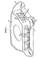
- the gas bag module in Figure 1 consists of a housing 10 and a gas bag cover 12.
- the housing 10 is substantially cuboid. On the side surfaces of the housing 10 holding parts 14, 14 'are mounted.
- the housing 10 may be designed as a plastic injection-molded part, wherein advantageously the holding parts 14, 14 'are mitangespritzt.
- the guide member 16 comprises a guide member 16 and two locking lugs 24.
- the guide member 16 consists of two guides 18 with L-shaped cross-section and a cross member 20.
- the guides 18 are fixedly attached to the end of their long legs on the housing, in such a way that their short thighs face each other. At the bottom of the picture, the short legs are connected by the cross member 20 with each other.
- the ends of the guides 18 together with the traverse 20 and the housing 10 form a passage 22.
- two locking lugs 24 are formed on the housing 10.
- the latching lugs 24 extend parallel to one another and have a ramp surface 26 and a flat, rounded head 28.
- the ramp surfaces 26 of the locking lugs 24 are facing the traverse 20.
- the locking lugs 24 are molded on the housing 10 as formations. Since they do not have to be movable, they have no undercuts. This ensures a cost-effective production, since no complicated injection mold is required. In addition, the locking lugs are very stable because they are connected at their entire base with the housing.
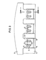
- the guides 18 are not parallel to each other, but starting from the passage 22 in the direction of the heads 28 of the locking lugs 24 towards each other. In this case, the shorter legs of the guides 18 taper in a wedge shape.
- Figure 1 it can be seen that on the longitudinal side of the housing 10, three such holding parts 14 are attached. On the narrow side of the housing 10, two holding parts 14 'are attached, which are each provided only with a latching lug. The same applies to the narrow side not visible in FIG. 1, while three guide elements 14, each with two latching noses, are again mounted on the non-visible longitudinal side.
- the number of holding parts per side and the type, whether with one, two or more locking lugs, is exemplified here and can be adjusted depending on the application, for example, on the size of the housing and the required connection force.
- FIG. 1 is also seen that on the housing 10 side facing the airbag cover 12, a bead 30 is formed.
- the airbag cover 12 is placed from below on the housing 10, so that the bead 30 encloses the lower edge of the housing 10.
- At the upper edge of the bead 30 holding parts in the form of tabs 32, 32 'are formed. These tabs 32, 32 'extend through the passages 22 and along the guides 18 of the holding parts 14, 14' on the housing 10.
- In the tabs 32, 32 'openings 34 are recessed, in which the locking lugs 24 engage. According to the number of locking lugs 24 are in the tabs 32, 32 'respectively two or an opening available.
- the gas bag cover 12 may advantageously be a plastic injection molded part.
- the airbag cover 12 is pushed onto the housing, so that the tabs 32, 32 'pass through the passages 22.
- the height of the locking lugs determines the strength of the warping of the tabs. The higher the locking lugs are, but the larger is also the surface for the force that can be transmitted between the holding parts. However, the maximum possible warping is also limited by the thickness of the tabs. In the embodiment shown, the height of the locking lugs 24 is selected so that they just through the tabs 32, 32 'protrude. Thus, the maximum engagement surface for the connection force is present and the connection optimally secured against unintentional loosening. Namely, if the latches engage only partially in the openings, the tabs and the locking lugs could bend at a high connection force by acting on the attack surface moment. This would mean that the attack surface is no longer perpendicular to the connection force and therefore the tabs can slip off the locking lugs.
- a micro-tooth 34 is formed. Such a micro-toothing is shown in the enlarged section in FIG. 4.
- an airbag module is only an example of the application of the locking connection according to the invention. Numerous changes are conceivable, the holding parts with the guide elements and the locking lugs can just as well be attached to the gas bag cover and the tabs on the housing.
- the locking lugs may be attached to the tabs instead of the housing, wherein the ramp surface would have to point in the other direction.
- the openings would then be provided in the housing and omit the crossbar, so that the tabs curl when inserted into the guides until the latches can engage in the openings on the housing.
Landscapes
- Engineering & Computer Science (AREA)
- Mechanical Engineering (AREA)
- Air Bags (AREA)
- Snaps, Bayonet Connections, Set Pins, And Snap Rings (AREA)
Description
Die Erfindung betrifft eine Rastverbindung, insbesondere für eine Gassack-Abdeckung eines Fahrzeuginsassen-Rückhaltesystems, gemäß dem Oberbegriff des Anspruchs 1.The invention relates to a latching connection, in particular for a gas bag cover of a vehicle occupant restraint system, according to the preamble of claim 1.
Bei derartigen Rastverbindungen weist üblicherweise das andere Halteteil eine Öffnung auf. Zum Einrasten der Verbindung werden die beiden Halteteile gegeneinander verschoben. Dabei wird die Rastnase durch das andere Halteteil eingedrückt, bis die Öffnung über der Rastnase liegt und diese einschnappen kann. Damit die Rastnase entsprechend beweglich ist, muß sie aus ausreichend dünnem Material geformt sein. Dies setzt aber die Festigkeit der Rastverbindung herab. Außerdem besteht die Gefahr, daß die Rastnase beim Eindrücken oder beim Wiederlösen der Rastverbindung eine bleibende Verformung erleidet, so daß sie beim nächsten Zusammenfügen nicht mehr einrastet oder gar abbricht.In such snap-in connections, usually the other holding part has an opening. To engage the connection, the two holding parts are moved against each other. The locking lug is pressed by the other holding part until the opening is above the locking lug and this can snap. Thus, the latch is correspondingly movable, it must be formed of sufficiently thin material. However, this reduces the strength of the locking connection. In addition, there is the danger that the latch when pressing or when re-releasing the latching connection suffers a permanent deformation, so that they no longer locks in the next assembly or even breaks off.
Eine Rastverbindung gemäß dem Oberbegriff des Anspruchs 1 ist aus der US-A-5,876,060 bekannt. Die Rastnase ist an einer freitragenden Zunge angeordnet, die elastisch ausgelenkt wird, wenn eine Lasche zwischen die ihr zugeordnete Führung eingeschoben wird.A latching connection according to the preamble of claim 1 is known from US-A-5,876,060. The detent is disposed on a cantilevered tongue which is resiliently deflected when a tab is inserted between its associated guide.
Die Erfindung schafft eine Rastverbindung, die die genannten Nachteile vermeidet und die darüber hinaus einfach und kostengünstig herzustellen und anzuwenden ist.The invention provides a latching connection which avoids the disadvantages mentioned and which moreover is simple and inexpensive to produce and to use.
Zu diesem Zweck sind erfindungsgemäß die Merkmale des Anspruchs 1 vorgesehen. Damit ist es nicht mehr erforderlich, die Rastnase elastisch beweglich zu gestalten, so daß sie entsprechend massiv und stabil ausgeführt sein kann. Die zum Einrasten der Verbindung erforderliche federnde Wirkung wird durch die Wölbung der Lasche erzeugt.For this purpose, the features of claim 1 are provided according to the invention. Thus, it is no longer necessary to make the locking lug elastically movable, so that they can be made correspondingly solid and stable. The spring effect required for engaging the connection is generated by the curvature of the tab.
Weitere Einzelheiten und Ausgestaltungen der Erfindung und deren Vorteile ergeben sich aus der nachfolgenden Beschreibung einer beispielhaften Ausführungsform, die in den beigefügten Abbildungen dargestellt ist, in welchen zeigen:
- Figur 1 eine perspektivische Ansicht eines Gassackmoduls mit einer Rastverbindung gemäß einer bevorzugten Ausführungsform der Erfindung;
- Figur 2 ein Detail eines Halteteils des Gassackmoduls aus Figur 1;
- Figur 3 eine Ansicht einer Seite des Gassackmoduls aus Figur 1;
- Figur 4 einen Schnitt durch das Gassackmodul aus Figur 3 entlang der Linie IV-IV und
- Figure 1 is a perspective view of a gas bag module with a latching connection according to a preferred embodiment of the invention;
- Figure 2 shows a detail of a holding part of the gas bag module of Figure 1;
- Figure 3 is a view of one side of the gas bag module of Figure 1;
- Figure 4 shows a section through the gas bag module of Figure 3 along the line IV-IV and
Das Gassackmodul in Figur 1 besteht aus einem Gehäuse 10 und einer Gassack-Abdeckung 12. In der Abbildung ist die am Lenkrad zu befestigende Seite des Gehäuses 10 obenauf; die zum Fahrzeuginsassen weisende Seite der Gassackabdeckung 12 ist unten.The gas bag module in Figure 1 consists of a
Das Gehäuse 10 ist im wesentlichen quaderförmig. An den Seitenflächen des Gehäuses 10 sind Halteteile 14, 14' angebracht. Das Gehäuse 10 kann als Kunststoff-Spritzgußteil ausgeführt sein, wobei vorteilhafterweise die Halteteile 14, 14' mitangespritzt sind.The
In Figur 2 ist eines der Halteteile 14 genauer zu sehen. Das Halteteil 14 umfaßt ein Führungselement 16 und zwei Rastnasen 24. Das Führungselement 16 besteht aus zwei Führungen 18 mit L-förmigem Querschnitt und einer Traverse 20. Die Führungen 18 sind am Ende ihrer langen Schenkel fest an dem Gehäuse angebracht, und zwar so, daß sich ihre kurzen Schenkel gegenüberstehen. Am im Bild unteren Ende sind die kurzen Schenkel durch die Traverse 20 miteinander verbunden. Somit bilden die Enden der Führungen 18 zusammen mit der Traverse 20 und dem Gehäuse 10 einen Durchgang 22. Zwischen den beiden Führungen 18 sind am Gehäuse 10 zwei Rastnasen 24 ausgebildet. Die Rastnasen 24 verlaufen parallel zueinander und weisen eine Rampenfläche 26 und einen ebenen, abgerundeten Kopf 28 auf. Die Rampenflächen 26 der Rastnasen 24 sind der Traverse 20 zugewandt. Die Rastnasen 24 sind am Gehäuse 10 als Ausformungen angespritzt. Da sie nicht beweglich sein müssen, weisen sie keine Hinterschneidungen auf. Dies gewährleistet eine kostengünstige Herstellung, da keine komplizierte Spritzform erforderlich ist. Zudem sind die Rastnasen sehr stabil, weil sie an ihrer gesamten Grundfläche mit dem Gehäuse verbunden sind.In Figure 2, one of the
Wie in Figur 3 besser zu sehen ist, verlaufen die Führungen 18 nicht parallel zueinander, sondern vom Durchgang 22 ausgehend in Richtung der Köpfe 28 der Rastnasen 24 aufeinander zu. Dabei verjüngen sich die kürzeren Schenkel der Führungen 18 keilförmig. In Abbildung 1 ist zu sehen, daß an der Längsseite des Gehäuses 10 drei derartige Halteteile 14 angebracht sind. An der Schmalseite des Gehäuses 10 sind zwei Halteteile 14' angebracht, die jeweils nur mit einer Rastnase versehen sind. Dasselbe gilt für die in Figur 1 nicht sichtbare Schmalseite, während auf der nicht sichtbaren Längsseite wiederum drei Führungselemente 14 mit jeweils zwei Rastnasen angebracht sind. Die Anzahl der Halteteile je Seite und die Art, ob mit einer, zwei oder mehr Rastnasen, ist hier beispielhaft dargestellt und kann je nach Anwendung, beispielsweise auf die Größe des Gehäuses und auf die erforderliche Verbindungskraft, abgestimmt werden.As can be better seen in Figure 3, the
In Figur 1 ist ebenfalls zu sehen, daß an der dem Gehäuse 10 zugewandten Seite der Gassackabdeckung 12 eine Wulst 30 ausgebildet ist. Die Gassackabdeckung 12 ist von unten auf das Gehäuse 10 aufgesetzt, so daß die Wulst 30 den unteren Rand des Gehäuses 10 umschließt. Am oberen Rand der Wulst 30 sind Halteteile in Form von Laschen 32, 32' ausgebildet. Diese Laschen 32, 32' erstrecken sich durch die Durchgänge 22 und entlang der Führungen 18 der Halteteile 14, 14' am Gehäuse 10. In den Laschen 32, 32' sind Öffnungen 34 ausgespart, in welche die Rastnasen 24 eingreifen. Entsprechend der Anzahl der Rastnasen 24 sind in den Laschen 32, 32' jeweils zwei bzw. eine Öffnung vorhanden. Auch die Gassackabdeckung 12 kann vorteilhafterweise ein Kunststoffspritzgußteil sein.In Figure 1 is also seen that on the
Bei der Montage wird die Gassackabdeckung 12 auf das Gehäuse aufgeschoben, so daß die Laschen 32, 32' die Durchgänge 22 passieren. Dabei werden die Laschen 32, 32' von den aufeinander zu verlaufenden Führungen 18 geleitet, so daß Gehäuse 10 und Gassackabdeckung 12 relativ zueinander in die richtige Position kommen. Beim Einschieben der Laschen 32, 32' gleiten diese auf den Rampenflächen 26 und werden von diesen zwischen den Führungen 18 senkrecht zur Verschieberichtung gewölbt. Erst wenn sich die Öffnungen 34 über den Rastnasen 24 befinden, können sich die Laschen 32, 32' aufgrund ihrer Elastizität wieder strecken, wobei die Rastnasen 24 in die Öffnungen 34 eingreifen und damit die Rastverbindung hergestellt ist (Fig. 4).During assembly, the
Die Höhe der Rastnasen bestimmt die Stärke der Verwölbung der Laschen. Je höher die Rastnasen sind, desto größer ist aber auch die Angriffsfläche für die Kraft, die zwischen den Halteteilen übertragen werden kann. Die maximal mögliche Verwölbung ist allerdings auch durch die Dicke der Laschen begrenzt. In der gezeigten Ausführungsform ist die Höhe der Rastnasen 24 so gewählt, daß diese gerade noch durch die Laschen 32, 32' hindurchragen. Damit ist die maximale Angriffsfläche für die Verbindungskraft vorhanden und die Verbindung gegen unbeabsichtigtes Lösen optimal gesichert. Wenn die Rastnasen nämlich nur zum Teil in die Öffnungen eingreifen, könnten sich die Laschen und die Rastnasen bei einer hohen Verbindungskraft durch das an der Angriffsfläche wirkende Moment verbiegen. Dies hätte zur Folge, daß die Angriffsfläche nicht mehr senkrecht zur Verbindungskraft steht und deshalb die Laschen von den Rastnasen abrutschen können.The height of the locking lugs determines the strength of the warping of the tabs. The higher the locking lugs are, but the larger is also the surface for the force that can be transmitted between the holding parts. However, the maximum possible warping is also limited by the thickness of the tabs. In the embodiment shown, the height of the
Das Abrutschen der Laschen von den Rastnasen kann alternativ oder zusätzlich dadurch verhindert werden, daß beispielsweise am Kopf 28 der Rastnase 24 eine Mikroverzahnung 34 ausgebildet ist. Eine derartige Mikroverzahnung ist in dem vergrößerten Ausschnitt in Fig. 4 dargestellt.The slipping of the tabs of the locking lugs can be alternatively or additionally prevented by, for example, the head 28th the detent 24 a micro-tooth 34 is formed. Such a micro-toothing is shown in the enlarged section in FIG. 4.
Die gezeigte Ausführungsform eines Gassackmoduls stellt nur ein Beispiel für die Anwendung der erfindungsgemäßen Rastverbindung dar. Zahlreiche Veränderungen sind denkbar, so können die Halteteile mit den Führungselementen und den Rastnasen genausogut an der Gassack-abdeckung und die Laschen an dem Gehäuse angebracht sein.The embodiment shown of an airbag module is only an example of the application of the locking connection according to the invention. Numerous changes are conceivable, the holding parts with the guide elements and the locking lugs can just as well be attached to the gas bag cover and the tabs on the housing.
In einer anderen Ausführungsform können die Rastnasen statt am Gehäuse an den Laschen angebracht sein, wobei die Rampenfläche in die andere Richtung weisen müßte. Die Öffnungen wären dann im Gehäuse vorzusehen und die Traverse wegzulassen, so daß sich die Laschen beim Einschieben in die Führungen verwölben, bis die Rastnasen in die Öffnungen am Gehäuse eingreifen können.In another embodiment, the locking lugs may be attached to the tabs instead of the housing, wherein the ramp surface would have to point in the other direction. The openings would then be provided in the housing and omit the crossbar, so that the tabs curl when inserted into the guides until the latches can engage in the openings on the housing.
Claims (5)
- A detent connection, in particular for a gas bag cover (12) of a vehicle occupant restraint system, comprising two retaining parts (14, 14', 32, 32'), one of the retaining parts (14, 14') being provided with at least one detent nose (24), the detent nose being configured such that upon shifting of the two retaining parts relative to each other, one of the retaining parts (32, 32') is arched by a force acting substantially perpendicularly to the shifting direction before the detent nose latches in place, one retaining part (32, 32') being configured as a tab and the other retaining part (14, 14') having guide elements (16) by means of which the tab (32, 32') is guided, characterized in that the tab (32, 32') is guided by the guide elements (16) such that it is arched between the two guide elements perpendicularly to the shifting direction until the detent nose latches in place.
- The detent connection as set forth in claim 1, characterized in that one of the retaining parts (32, 32') has at least one opening (34) into which the detent nose (24) engages.
- A gas bag module comprising a detent connection as set forth in either of the preceding claims, characterized in that one of the retaining parts (32, 32') is firmly connected to the cover (12).
- A gas bag module comprising a detent connection as set forth in either of claims 1 and 2, characterized in that one of the retaining parts (14, 14') is firmly connected to the housing (10).
- A gas bag module comprising a detent connection as set forth in either of claims 1 and 2, characterized in that the detent nose (24) is provided with a microserration (34).
Applications Claiming Priority (2)
| Application Number | Priority Date | Filing Date | Title |
|---|---|---|---|
| DE29920024U DE29920024U1 (en) | 1999-11-15 | 1999-11-15 | Snap connection |
| DE29920024U | 1999-11-15 |
Publications (3)
| Publication Number | Publication Date |
|---|---|
| EP1101954A2 EP1101954A2 (en) | 2001-05-23 |
| EP1101954A3 EP1101954A3 (en) | 2002-12-11 |
| EP1101954B1 true EP1101954B1 (en) | 2007-03-14 |
Family
ID=8081610
Family Applications (1)
| Application Number | Title | Priority Date | Filing Date |
|---|---|---|---|
| EP00120152A Expired - Lifetime EP1101954B1 (en) | 1999-11-15 | 2000-09-21 | Snap-in connection |
Country Status (3)
| Country | Link |
|---|---|
| US (1) | US6409208B1 (en) |
| EP (1) | EP1101954B1 (en) |
| DE (2) | DE29920024U1 (en) |
Families Citing this family (15)
| Publication number | Priority date | Publication date | Assignee | Title |
|---|---|---|---|---|
| DE10016514B4 (en) * | 2000-04-03 | 2006-04-06 | Autoliv Development Ab | Steering wheel with triggered by displacement of the airbag module horn function |
| US20020024197A1 (en) * | 2000-08-30 | 2002-02-28 | Breed Automotive Technologies, Inc. | Air bag module |
| DE20113806U1 (en) | 2001-08-21 | 2002-02-28 | Breed Automotive Technology, Inc., Lakeland, Fla. | Airbag module with snap connection |
| US6752415B2 (en) * | 2001-10-05 | 2004-06-22 | Autoliv Asp, Inc. | Airbag module Z-height control tab |
| US6959943B2 (en) * | 2002-11-18 | 2005-11-01 | Autoliv Asp, Inc. | Deflectable airbag housing mounting tabs |
| DE102005004128B4 (en) * | 2004-03-23 | 2014-01-02 | Trw Automotive Gmbh | Cover for a gas bag module |
| DE202004004556U1 (en) * | 2004-03-23 | 2004-08-12 | Trw Automotive Gmbh | Cover for an airbag module |
| US7374198B2 (en) * | 2004-04-02 | 2008-05-20 | Toyoda Gosei Co., Ltd | Airbag module canister |
| US7527286B2 (en) * | 2004-07-29 | 2009-05-05 | Intier Automotive Inc. | Air bag door and chute |
| DE102005027271B4 (en) * | 2005-06-08 | 2011-06-01 | Takata-Petri Ag | Cover for an airbag module |
| DE102010034114A1 (en) * | 2010-08-12 | 2012-02-16 | Gm Global Technology Operations Llc (N.D.Ges.D. Staates Delaware) | Airbag arrangement with a separate firing channel |
| US8944460B2 (en) * | 2011-06-30 | 2015-02-03 | Ford Global Technologies, Llc | Air bag chute topper system |
| KR102146661B1 (en) * | 2013-11-29 | 2020-08-21 | 현대모비스 주식회사 | An airbag module of vehicle |
| US9415738B2 (en) | 2014-12-22 | 2016-08-16 | Ford Global Technologies, Llc | Anti-rattle interface for airbag chute to airbag module |
| KR20210126327A (en) * | 2020-04-10 | 2021-10-20 | 현대모비스 주식회사 | Driver seat airbag |
Family Cites Families (11)
| Publication number | Priority date | Publication date | Assignee | Title |
|---|---|---|---|---|
| JPH0694267B2 (en) * | 1990-05-24 | 1994-11-24 | タカタ株式会社 | Airbag device |
| JP2567134Y2 (en) * | 1993-01-22 | 1998-03-30 | 矢崎総業株式会社 | Double locking connector |
| JPH07233805A (en) * | 1994-02-23 | 1995-09-05 | Unisia Jecs Corp | Unit attaching structure |
| US5474323A (en) * | 1994-06-08 | 1995-12-12 | Takata, Inc. | Passenger air bag module with snap-attachment deployment cover |
| US5445409A (en) * | 1994-10-17 | 1995-08-29 | General Motors Corporation | Passenger airbag snap-on deployment door |
| US5511819A (en) * | 1995-03-27 | 1996-04-30 | Morton International, Inc. | Fastenerless automotive passenger airbag module endcap |
| US5588669A (en) * | 1995-04-26 | 1996-12-31 | Morton International, Inc. | Cover attachment for an air bag module |
| JP3651068B2 (en) * | 1995-07-31 | 2005-05-25 | 豊田合成株式会社 | Airbag device |
| JP3155691B2 (en) * | 1995-09-12 | 2001-04-16 | 矢崎総業株式会社 | Lock structure for assembled parts |
| JP3003578B2 (en) * | 1996-07-22 | 2000-01-31 | 株式会社デンソー | Casing for airbag device of vehicle and cover member therefor |
| US5876060A (en) * | 1996-12-05 | 1999-03-02 | Takata, Inc. | Seat mounted side impact module |
-
1999
- 1999-11-15 DE DE29920024U patent/DE29920024U1/en not_active Expired - Lifetime
-
2000
- 2000-09-21 DE DE50014156T patent/DE50014156D1/en not_active Expired - Lifetime
- 2000-09-21 EP EP00120152A patent/EP1101954B1/en not_active Expired - Lifetime
- 2000-09-29 US US09/675,605 patent/US6409208B1/en not_active Expired - Fee Related
Also Published As
| Publication number | Publication date |
|---|---|
| EP1101954A2 (en) | 2001-05-23 |
| US6409208B1 (en) | 2002-06-25 |
| DE50014156D1 (en) | 2007-04-26 |
| DE29920024U1 (en) | 2000-03-30 |
| EP1101954A3 (en) | 2002-12-11 |
Similar Documents
| Publication | Publication Date | Title |
|---|---|---|
| EP1101954B1 (en) | Snap-in connection | |
| EP2057043B1 (en) | Device for snap-fastening an airbag unit in a subassembly of a motor vehicle, especially in a steering wheel | |
| DE69508569T2 (en) | SECONDARY INTERLOCKING ELEMENT | |
| EP0129248B1 (en) | Safety belt buckle | |
| DE102010016591A1 (en) | Drawer has inner space, which is limited at opposite sides by side panels, where separating element for partitioning of inner space is provided between side panels | |
| EP1255650A1 (en) | Self-inking stamp | |
| EP2183736B1 (en) | Identification device for electrical lines | |
| WO2006024438A1 (en) | Electrical connecting module | |
| DE2515842C2 (en) | Screwless clamp | |
| DE1557427B1 (en) | Buckle for a seat belt | |
| DE102006010309A1 (en) | Plug socket clamp, has bearing provided at insert part which is centrally arranged in housing between different contact pieces, and release key is arranged between bearing and contact tongue | |
| EP1489712B1 (en) | Strain relief for electrical cable | |
| DE10056835A1 (en) | Air bag module housing for motor vehicle has pair of holders to clamp bag between tem in housing | |
| DE19600236A1 (en) | Electrical connector housing element | |
| DE4202819C2 (en) | Lock for safety belts | |
| DE68922343T2 (en) | Device for pulling fuses. | |
| DE10035726A1 (en) | Contact carrier for seat belts, air bags in motor vehicles, has slider held by element that releases slider loaded by spring, when latching arms projected in plug-in direction is received at latching recess of socket | |
| EP1243078B1 (en) | Electrical device comprising a housing | |
| DE20109717U1 (en) | Headrest sleeve for a guide rod of a headrest | |
| DE4301949C2 (en) | Plug contact socket for a flat pin | |
| DE60027072T2 (en) | Electrical plug connection, in particular for motor vehicle applications | |
| EP0989760B1 (en) | Terminal block for telecommunications | |
| EP0093236B1 (en) | Plug for an apparatus | |
| DE20217461U1 (en) | Electrical plug connector especially for motor vehicles has locking element that has positive fit unlocked state with respect to housing and is deconnectable in locking direction | |
| DE3136755A1 (en) | Apparatus for receiving cassettes, having a locking mechanism provided with at least one outwardly extendable locking element |
Legal Events
| Date | Code | Title | Description |
|---|---|---|---|
| PUAI | Public reference made under article 153(3) epc to a published international application that has entered the european phase |
Free format text: ORIGINAL CODE: 0009012 |
|
| AK | Designated contracting states |
Kind code of ref document: A2 Designated state(s): AT BE CH CY DE DK ES FI FR GB GR IE IT LI LU MC NL PT SE |
|
| AX | Request for extension of the european patent |
Free format text: AL;LT;LV;MK;RO;SI |
|
| RIN1 | Information on inventor provided before grant (corrected) |
Inventor name: DERRICK, JOHN-OLIVER Inventor name: FRISCH, RALPH |
|
| PUAL | Search report despatched |
Free format text: ORIGINAL CODE: 0009013 |
|
| AK | Designated contracting states |
Kind code of ref document: A3 Designated state(s): AT BE CH CY DE DK ES FI FR GB GR IE IT LI LU MC NL PT SE |
|
| AX | Request for extension of the european patent |
Free format text: AL;LT;LV;MK;RO;SI |
|
| 17P | Request for examination filed |
Effective date: 20030605 |
|
| AKX | Designation fees paid |
Designated state(s): DE ES FR GB IT |
|
| GRAP | Despatch of communication of intention to grant a patent |
Free format text: ORIGINAL CODE: EPIDOSNIGR1 |
|
| GRAS | Grant fee paid |
Free format text: ORIGINAL CODE: EPIDOSNIGR3 |
|
| GRAA | (expected) grant |
Free format text: ORIGINAL CODE: 0009210 |
|
| AK | Designated contracting states |
Kind code of ref document: B1 Designated state(s): DE ES FR GB IT |
|
| RAP1 | Party data changed (applicant data changed or rights of an application transferred) |
Owner name: TRW AUTOMOTIVE SAFETY SYSTEMS GMBH |
|
| REG | Reference to a national code |
Ref country code: GB Ref legal event code: FG4D Free format text: NOT ENGLISH |
|
| REF | Corresponds to: |
Ref document number: 50014156 Country of ref document: DE Date of ref document: 20070426 Kind code of ref document: P |
|
| PG25 | Lapsed in a contracting state [announced via postgrant information from national office to epo] |
Ref country code: ES Free format text: LAPSE BECAUSE OF FAILURE TO SUBMIT A TRANSLATION OF THE DESCRIPTION OR TO PAY THE FEE WITHIN THE PRESCRIBED TIME-LIMIT Effective date: 20070625 |
|
| GBV | Gb: ep patent (uk) treated as always having been void in accordance with gb section 77(7)/1977 [no translation filed] |
Effective date: 20070314 |
|
| EN | Fr: translation not filed | ||
| EN | Fr: translation not filed | ||
| PG25 | Lapsed in a contracting state [announced via postgrant information from national office to epo] |
Ref country code: GB Free format text: LAPSE BECAUSE OF FAILURE TO SUBMIT A TRANSLATION OF THE DESCRIPTION OR TO PAY THE FEE WITHIN THE PRESCRIBED TIME-LIMIT Effective date: 20070314 |
|
| PLBE | No opposition filed within time limit |
Free format text: ORIGINAL CODE: 0009261 |
|
| STAA | Information on the status of an ep patent application or granted ep patent |
Free format text: STATUS: NO OPPOSITION FILED WITHIN TIME LIMIT |
|
| 26N | No opposition filed |
Effective date: 20071217 |
|
| PG25 | Lapsed in a contracting state [announced via postgrant information from national office to epo] |
Ref country code: IT Free format text: LAPSE BECAUSE OF FAILURE TO SUBMIT A TRANSLATION OF THE DESCRIPTION OR TO PAY THE FEE WITHIN THE PRESCRIBED TIME-LIMIT Effective date: 20070314 Ref country code: FR Free format text: LAPSE BECAUSE OF FAILURE TO SUBMIT A TRANSLATION OF THE DESCRIPTION OR TO PAY THE FEE WITHIN THE PRESCRIBED TIME-LIMIT Effective date: 20071102 |
|
| PG25 | Lapsed in a contracting state [announced via postgrant information from national office to epo] |
Ref country code: FR Free format text: LAPSE BECAUSE OF FAILURE TO SUBMIT A TRANSLATION OF THE DESCRIPTION OR TO PAY THE FEE WITHIN THE PRESCRIBED TIME-LIMIT Effective date: 20070314 |
|
| PGFP | Annual fee paid to national office [announced via postgrant information from national office to epo] |
Ref country code: DE Payment date: 20190930 Year of fee payment: 20 |
|
| REG | Reference to a national code |
Ref country code: DE Ref legal event code: R071 Ref document number: 50014156 Country of ref document: DE |