EP1101935B1 - Methode und schiff zur installation von windkraftanlagen auf see - Google Patents
Methode und schiff zur installation von windkraftanlagen auf see Download PDFInfo
- Publication number
- EP1101935B1 EP1101935B1 EP00125114A EP00125114A EP1101935B1 EP 1101935 B1 EP1101935 B1 EP 1101935B1 EP 00125114 A EP00125114 A EP 00125114A EP 00125114 A EP00125114 A EP 00125114A EP 1101935 B1 EP1101935 B1 EP 1101935B1
- Authority
- EP
- European Patent Office
- Prior art keywords
- unit
- lifting
- vessel
- windmill
- mill
- Prior art date
- Legal status (The legal status is an assumption and is not a legal conclusion. Google has not performed a legal analysis and makes no representation as to the accuracy of the status listed.)
- Expired - Lifetime
Links
Images


Classifications
-
- E—FIXED CONSTRUCTIONS
- E02—HYDRAULIC ENGINEERING; FOUNDATIONS; SOIL SHIFTING
- E02D—FOUNDATIONS; EXCAVATIONS; EMBANKMENTS; UNDERGROUND OR UNDERWATER STRUCTURES
- E02D27/00—Foundations as substructures
- E02D27/32—Foundations for special purposes
- E02D27/42—Foundations for poles, masts or chimneys
-
- B—PERFORMING OPERATIONS; TRANSPORTING
- B63—SHIPS OR OTHER WATERBORNE VESSELS; RELATED EQUIPMENT
- B63B—SHIPS OR OTHER WATERBORNE VESSELS; EQUIPMENT FOR SHIPPING
- B63B27/00—Arrangement of ship-based loading or unloading equipment for cargo or passengers
- B63B27/10—Arrangement of ship-based loading or unloading equipment for cargo or passengers of cranes
-
- B—PERFORMING OPERATIONS; TRANSPORTING
- B63—SHIPS OR OTHER WATERBORNE VESSELS; RELATED EQUIPMENT
- B63B—SHIPS OR OTHER WATERBORNE VESSELS; EQUIPMENT FOR SHIPPING
- B63B35/00—Vessels or similar floating structures specially adapted for specific purposes and not otherwise provided for
- B63B35/003—Vessels or similar floating structures specially adapted for specific purposes and not otherwise provided for for transporting very large loads, e.g. offshore structure modules
-
- B—PERFORMING OPERATIONS; TRANSPORTING
- B66—HOISTING; LIFTING; HAULING
- B66C—CRANES; LOAD-ENGAGING ELEMENTS OR DEVICES FOR CRANES, CAPSTANS, WINCHES, OR TACKLES
- B66C23/00—Cranes comprising essentially a beam, boom, or triangular structure acting as a cantilever and mounted for translatory of swinging movements in vertical or horizontal planes or a combination of such movements, e.g. jib-cranes, derricks, tower cranes
- B66C23/18—Cranes comprising essentially a beam, boom, or triangular structure acting as a cantilever and mounted for translatory of swinging movements in vertical or horizontal planes or a combination of such movements, e.g. jib-cranes, derricks, tower cranes specially adapted for use in particular purposes
- B66C23/36—Cranes comprising essentially a beam, boom, or triangular structure acting as a cantilever and mounted for translatory of swinging movements in vertical or horizontal planes or a combination of such movements, e.g. jib-cranes, derricks, tower cranes specially adapted for use in particular purposes mounted on road or rail vehicles; Manually-movable jib-cranes for use in workshops; Floating cranes
- B66C23/52—Floating cranes
-
- E—FIXED CONSTRUCTIONS
- E02—HYDRAULIC ENGINEERING; FOUNDATIONS; SOIL SHIFTING
- E02B—HYDRAULIC ENGINEERING
- E02B17/00—Artificial islands mounted on piles or like supports, e.g. platforms on raisable legs or offshore constructions; Construction methods therefor
-
- E—FIXED CONSTRUCTIONS
- E02—HYDRAULIC ENGINEERING; FOUNDATIONS; SOIL SHIFTING
- E02D—FOUNDATIONS; EXCAVATIONS; EMBANKMENTS; UNDERGROUND OR UNDERWATER STRUCTURES
- E02D27/00—Foundations as substructures
- E02D27/32—Foundations for special purposes
- E02D27/42—Foundations for poles, masts or chimneys
- E02D27/425—Foundations for poles, masts or chimneys specially adapted for wind motors masts
-
- F—MECHANICAL ENGINEERING; LIGHTING; HEATING; WEAPONS; BLASTING
- F03—MACHINES OR ENGINES FOR LIQUIDS; WIND, SPRING, OR WEIGHT MOTORS; PRODUCING MECHANICAL POWER OR A REACTIVE PROPULSIVE THRUST, NOT OTHERWISE PROVIDED FOR
- F03D—WIND MOTORS
- F03D13/00—Assembly, mounting or commissioning of wind motors; Arrangements specially adapted for transporting wind motor components
- F03D13/10—Assembly of wind motors; Arrangements for erecting wind motors
-
- F—MECHANICAL ENGINEERING; LIGHTING; HEATING; WEAPONS; BLASTING
- F03—MACHINES OR ENGINES FOR LIQUIDS; WIND, SPRING, OR WEIGHT MOTORS; PRODUCING MECHANICAL POWER OR A REACTIVE PROPULSIVE THRUST, NOT OTHERWISE PROVIDED FOR
- F03D—WIND MOTORS
- F03D13/00—Assembly, mounting or commissioning of wind motors; Arrangements specially adapted for transporting wind motor components
- F03D13/20—Arrangements for mounting or supporting wind motors; Masts or towers for wind motors
- F03D13/25—Arrangements for mounting or supporting wind motors; Masts or towers for wind motors specially adapted for offshore installation
-
- F—MECHANICAL ENGINEERING; LIGHTING; HEATING; WEAPONS; BLASTING
- F03—MACHINES OR ENGINES FOR LIQUIDS; WIND, SPRING, OR WEIGHT MOTORS; PRODUCING MECHANICAL POWER OR A REACTIVE PROPULSIVE THRUST, NOT OTHERWISE PROVIDED FOR
- F03D—WIND MOTORS
- F03D13/00—Assembly, mounting or commissioning of wind motors; Arrangements specially adapted for transporting wind motor components
- F03D13/40—Arrangements or methods specially adapted for transporting wind motor components
-
- B—PERFORMING OPERATIONS; TRANSPORTING
- B63—SHIPS OR OTHER WATERBORNE VESSELS; RELATED EQUIPMENT
- B63B—SHIPS OR OTHER WATERBORNE VESSELS; EQUIPMENT FOR SHIPPING
- B63B35/00—Vessels or similar floating structures specially adapted for specific purposes and not otherwise provided for
- B63B35/44—Floating buildings, stores, drilling platforms, or workshops, e.g. carrying water-oil separating devices
- B63B2035/4433—Floating structures carrying electric power plants
- B63B2035/446—Floating structures carrying electric power plants for converting wind energy into electric energy
-
- E—FIXED CONSTRUCTIONS
- E02—HYDRAULIC ENGINEERING; FOUNDATIONS; SOIL SHIFTING
- E02B—HYDRAULIC ENGINEERING
- E02B17/00—Artificial islands mounted on piles or like supports, e.g. platforms on raisable legs or offshore constructions; Construction methods therefor
- E02B2017/0039—Methods for placing the offshore structure
- E02B2017/0047—Methods for placing the offshore structure using a barge
-
- E—FIXED CONSTRUCTIONS
- E02—HYDRAULIC ENGINEERING; FOUNDATIONS; SOIL SHIFTING
- E02B—HYDRAULIC ENGINEERING
- E02B17/00—Artificial islands mounted on piles or like supports, e.g. platforms on raisable legs or offshore constructions; Construction methods therefor
- E02B2017/0091—Offshore structures for wind turbines
-
- F—MECHANICAL ENGINEERING; LIGHTING; HEATING; WEAPONS; BLASTING
- F05—INDEXING SCHEMES RELATING TO ENGINES OR PUMPS IN VARIOUS SUBCLASSES OF CLASSES F01-F04
- F05B—INDEXING SCHEME RELATING TO WIND, SPRING, WEIGHT, INERTIA OR LIKE MOTORS, TO MACHINES OR ENGINES FOR LIQUIDS COVERED BY SUBCLASSES F03B, F03D AND F03G
- F05B2230/00—Manufacture
- F05B2230/60—Assembly methods
- F05B2230/61—Assembly methods using auxiliary equipment for lifting or holding
- F05B2230/6102—Assembly methods using auxiliary equipment for lifting or holding carried on a floating platform
-
- F—MECHANICAL ENGINEERING; LIGHTING; HEATING; WEAPONS; BLASTING
- F05—INDEXING SCHEMES RELATING TO ENGINES OR PUMPS IN VARIOUS SUBCLASSES OF CLASSES F01-F04
- F05B—INDEXING SCHEME RELATING TO WIND, SPRING, WEIGHT, INERTIA OR LIKE MOTORS, TO MACHINES OR ENGINES FOR LIQUIDS COVERED BY SUBCLASSES F03B, F03D AND F03G
- F05B2240/00—Components
- F05B2240/90—Mounting on supporting structures or systems
- F05B2240/93—Mounting on supporting structures or systems on a structure floating on a liquid surface
-
- F—MECHANICAL ENGINEERING; LIGHTING; HEATING; WEAPONS; BLASTING
- F05—INDEXING SCHEMES RELATING TO ENGINES OR PUMPS IN VARIOUS SUBCLASSES OF CLASSES F01-F04
- F05B—INDEXING SCHEME RELATING TO WIND, SPRING, WEIGHT, INERTIA OR LIKE MOTORS, TO MACHINES OR ENGINES FOR LIQUIDS COVERED BY SUBCLASSES F03B, F03D AND F03G
- F05B2240/00—Components
- F05B2240/90—Mounting on supporting structures or systems
- F05B2240/95—Mounting on supporting structures or systems offshore
-
- Y—GENERAL TAGGING OF NEW TECHNOLOGICAL DEVELOPMENTS; GENERAL TAGGING OF CROSS-SECTIONAL TECHNOLOGIES SPANNING OVER SEVERAL SECTIONS OF THE IPC; TECHNICAL SUBJECTS COVERED BY FORMER USPC CROSS-REFERENCE ART COLLECTIONS [XRACs] AND DIGESTS
- Y02—TECHNOLOGIES OR APPLICATIONS FOR MITIGATION OR ADAPTATION AGAINST CLIMATE CHANGE
- Y02E—REDUCTION OF GREENHOUSE GAS [GHG] EMISSIONS, RELATED TO ENERGY GENERATION, TRANSMISSION OR DISTRIBUTION
- Y02E10/00—Energy generation through renewable energy sources
- Y02E10/70—Wind energy
- Y02E10/72—Wind turbines with rotation axis in wind direction
-
- Y—GENERAL TAGGING OF NEW TECHNOLOGICAL DEVELOPMENTS; GENERAL TAGGING OF CROSS-SECTIONAL TECHNOLOGIES SPANNING OVER SEVERAL SECTIONS OF THE IPC; TECHNICAL SUBJECTS COVERED BY FORMER USPC CROSS-REFERENCE ART COLLECTIONS [XRACs] AND DIGESTS
- Y02—TECHNOLOGIES OR APPLICATIONS FOR MITIGATION OR ADAPTATION AGAINST CLIMATE CHANGE
- Y02E—REDUCTION OF GREENHOUSE GAS [GHG] EMISSIONS, RELATED TO ENERGY GENERATION, TRANSMISSION OR DISTRIBUTION
- Y02E10/00—Energy generation through renewable energy sources
- Y02E10/70—Wind energy
- Y02E10/727—Offshore wind turbines
-
- Y—GENERAL TAGGING OF NEW TECHNOLOGICAL DEVELOPMENTS; GENERAL TAGGING OF CROSS-SECTIONAL TECHNOLOGIES SPANNING OVER SEVERAL SECTIONS OF THE IPC; TECHNICAL SUBJECTS COVERED BY FORMER USPC CROSS-REFERENCE ART COLLECTIONS [XRACs] AND DIGESTS
- Y02—TECHNOLOGIES OR APPLICATIONS FOR MITIGATION OR ADAPTATION AGAINST CLIMATE CHANGE
- Y02P—CLIMATE CHANGE MITIGATION TECHNOLOGIES IN THE PRODUCTION OR PROCESSING OF GOODS
- Y02P70/00—Climate change mitigation technologies in the production process for final industrial or consumer products
- Y02P70/50—Manufacturing or production processes characterised by the final manufactured product
Definitions
- the present invention concerns a method for installing off-shore windmills, a vessel for such installation as defined in the preamble of claims 1 and 8, respectively, and a windmill as defined in the preamble of claim 14.
- buoyancy elements of considerable size are required for providing the necessary buoyancy and stability.
- windmills of the size expected to be installed at sea in larger number windmills of or with more than 500 kW installed power
- the buoyancy elements become substantially larger than those which may be integrated into a normal foundation within the usual economic limits. Therefore, it is necessary with temporary buoyancy elements which are to be of considerable size with the costs associated therewith.
- the handling of such elements at sea is no small task, and a part of the saving on the mounting of the mill is in danger of being lost by work on the buoyancy elements.
- Another substantial disadvantage is that the stability during the sinking on the selected site may raise problems.
- the float stability is typically impaired substantially, which implies an increased risk of capsizing.
- the stability problem during sinking will normally imply that a foundation with integrated, permanent buoyancy elements will need either complicated filling routines in mutually closed chambers or external stabilisation during sinking, e.g. support by a crane.
- For temporary buoyancy elements not integrated in the foundation there will typically be a need for similar arrangements or, alternatively, the possibility of the sinking occurring by lowering from the buoyancy elements.
- the object of the invention is to provide a method for installing windmills at sea, which minimises costs and risk, and which avoids the drawbacks connected with installation by the methods known hitherto.
- the vessel used is adapted to the structure in the way that it has a lifting height which is substantially reduced in relation to the lifting height of a normal floating crane and which may be made as a temporary installed structure on a standard vessel.
- the invention implies a number of advantages.
- Windmill and foundation may be mounted as a unit on land or at quay, and all mounting of cables and other accessories may be finished. Depending on the type of base (foundation) and other circumstances, even the possibility of test running on land may be achieved. Compared with the prior art methods, a very significant advantage is hereby achieved. Work as well as test running may occur under normal, favourable work and safety conditions and with much lower cost than at sea. Possible faults may also be repaired with far less costs. Landbased crane assistance may be provided at normal rates if necessary.
- Windmill and base may be shipped in one piece, typically by the same vessel performing lifting as well as transport and installation. This may occur with the mill tower oriented largely vertically without requirements of very high floating cranes and with the possibility of not damaging the mill construction which is the risk if transported horizontally and raised at the location for installing.
- the invention Compared with an arrangement with floating from a dry dock, is achieved the significant advantage that standardised vessels and tools may be used, and that temporary buoyancy elements do not have to be dismounted under difficult conditions at sea.
- the invention is achieved the advantage that the number of working hours at sea are reduced to the least possible.
- the vessel required according to the method may have a lifting height which is considerably reduced compared with the lifting height for a normal floating crane.
- the structure may be made as one or more separate units that may be mounted on a standard vessel, for example a standard offshore barge.
- the prior art disadvantages concerning availability at the desired time and cost level for normal floating cranes are very much reduced.
- the advantage at the lifting at sea that relative movements between transport vessel and floating crane caused by sea may be disregarded.
- the invention has the significant advantage that an expensive unit in demand, like a floating crane, is not to be used for pure transportation purposes.
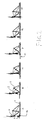
- Figure 1 shows a vessel made according to the invention.
- a standard offshore barge 1, e.g. with the dimensions 90 x 30 m, there is mounted two pairs of derricks, a front pair 2 and a rear pair 3.
- the derricks are identical and suspended by identical bearings 4 fastened to the deck of the vessel.
- the derricks carry a tackle arrangement 5. With suitable winches 6 the relative orientation of the derricks to vertical may be adjusted, and the suspended load may be hauled up and down.
- the vessel 1 is here a standard vessel of which the supply on the charter market is considerable and the prices moderate.
- the lifting arrangement in the shape of derricks 2-3, bearings 4 and winches 6 here constitute a separate unit which may be mounted on and dismounted from the standard vessel.
- FIG 2 shows an installation sequence using the vessel from Figure 1.
- the windmill 11 is seen erected on its base 9 on a quay 12.
- the vessel 1 is towed to the quay, and engagement has been made for lifting.
- the windmill is lifted and the derricks are adjusted so that the windmill is placed over the deck of the vessel.
- the windmill is lowered for resting on the deck, and the vessel is towed to the sea.
- the lift for installation is initiated at the previously prepared location 13.
- the derricks are adjusted again so that the windmill is positioned over its final location.
- the windmill is lowered onto its location.
- the lifting arrangement described in Figure 1 is based on separate, centrally actuated derricks and winches which largely distributes the load on the vessel as a series of point loads without any moments.
- the lifting arrangement may be embodied as one unit, or a small number of units, which by their fastening act on the vessel with a moment but which in return are easily mounted and dismounted.
- a lifting arrangement of this character is shown in Figure 3.
- a vessel 14 is provided with a steel construction 15 having a winch 16 and a tackle arrangement 17 which enables lifting of the windmill in the same way as previously indicated.
- a cantilever part 18 enables fixing the base 9 to the construction 15 when the windmill is lifted from the quay. This fixation provides the greatest possible stability during the sea transportation.
- FIG. 4 shows an installation sequence using the vessel of Figure 4.
- the windmill 11 is seen erected on its base 9 on a quay 12.
- the vessel 14 is towed to the quay, and engagement is made for lifting.
- the windmill is lifted, and the base is fastened to the cantilever part 18.
- the vessel is towed to the previously prepared location 13, and the windmill is positioned over its final location.
- the windmill is lowered upon its location.
Landscapes
- Engineering & Computer Science (AREA)
- General Engineering & Computer Science (AREA)
- Mechanical Engineering (AREA)
- Combustion & Propulsion (AREA)
- Chemical & Material Sciences (AREA)
- Life Sciences & Earth Sciences (AREA)
- Sustainable Development (AREA)
- Structural Engineering (AREA)
- Civil Engineering (AREA)
- Sustainable Energy (AREA)
- Paleontology (AREA)
- Mining & Mineral Resources (AREA)
- General Life Sciences & Earth Sciences (AREA)
- Ocean & Marine Engineering (AREA)
- Transportation (AREA)
- Wind Motors (AREA)
- Other Liquid Machine Or Engine Such As Wave Power Use (AREA)
Claims (14)
- Verfahren zum Errichten von Off-Shore-Windmühlen, bei dem die Hauptkomponenten der Windmühle (11) und des Sockels (10) an einem anderen Ort als dem endgültigen Aufstellungsort zu einer Einheit montiert werden und die vormontierte Einheit anschließend zum endgültigen Aufstellungsort verschifft und an diesem errichtet wird, dadurch gekennzeichnet, dass die Einheit mit einer im wesentlichen vertikalen Ausrichtung des Mühlenturms gehalten und an einem Punkt (L) am Mühlenturm oberhalb des Schwerpunktes (G) der Einheit gestützt wird, wenn die Einheit während des Verschiffens und während der Installation angehoben wird, und dass eine Hebestange (8) verwendet wird, welche mit einer am Mühlenturm befestigen Führung derart zusammenwirkt, dass die Hebewirkung an einer Stelle der Einheit mit ausreichender Tragekapazität unterhalb des Schwerpunktes (G) der Einheit angreift.
- Verfahren zum Errichten von Off-Shore-Windmühlen nach Anspruch 1, dadurch gekennzeichnet, dass die Einheit während des Transportes von einer Stützkonstruktion auf einem Schiff (1) derart herabhängt, dass sie mit der Unterseite des Sockels (10) im wesentlichen auf Seehöhe in einer Position innerhalb oder außerhalb des Schiffes (1) transportiert wird.
- Verfahren zum Errichten von Off-Shore-Windmühlen nach Anspruch 1, dadurch gekennzeichnet, dass die Einheit während des Transportes mit dem Sockel an einer Oberfläche des Schiffes abgestützt wird.
- Verfahren nach mindestens einem der vorhergehenden Ansprüche, dadurch gekennzeichnet, dass der Transport ohne Verwendung weiterer Auftriebselemente erfolgt.
- Verfahren nach mindestens einem der vorhergehenden Ansprüche, dadurch gekennzeichnet, dass der Sockel (10) der Windmühle von einem Schwerpunktsockel gebildet ist.
- Verfahren nach mindestens einem der vorhergehenden Ansprüche, dadurch gekennzeichnet, dass der Sockel der Windmühle zumindest abschnittsweise durch Pfähle gebildet ist.
- Verfahren nach mindestens einem der vorhergehenden Ansprüche, dadurch gekennzeichnet, dass das Anheben an einer Stelle im wesentlichen unterhalb der Spitze der Mühle, vorzugsweise an der unteren Hälfte der Mühlenkonstruktion, durchgeführt wird.
- Kombination aus einem Schiff zum Errichten von Off-Shore-Windmühlen und einer Windmühle, wobei die Hauptkomponenten der Windmühle (11) und des Sockels (10) an einem anderen Ort als dem endgültigen Aufstellungsort zu einer Einheit montiert werden und die vormontierte Einheit anschließend zum endgültigen Aufstellungsort verschifft und an diesem errichtet wird, während die Einheit mit einer im wesentlichen vertikalen Ausrichtung des Mühlenturms gehalten wird, wenn die Einheit während des Verschiffens und während der Installation angehoben wird, wobei das Schiff (1) eine Stützkonstruktion (4) mit einer Hebeeinheit (2, 3, 5, 6, 22) aufweist, welche Verbindungselemente (20) umfaßt, die zum Zusammenwirken mit zugeordneten, an einer Stelle oberhalb des Schwerpunktes (G) der Einheit am Mühlenturm angeordneten Verbindungselementen (20) vorgesehen sind, dadurch gekennzeichnet, dass das Schiff Hebestangen (8) aufweist, welche mit einer am Mühlenturm befestigten Führung (7) zusammenwirken und die Einheit an einer Stelle mit ausreichender Tragfähigkeit unterhalb des Schwerpunktes (G) der Einheit anheben, und dass die Stützkonstruktion eine maximale Höhe aufweist, welche im wesentlichen geringer als die Höhe der Spitze der Mühle (11) ist.
- Kombination nach Anspruch 8, dadurch gekennzeichnet, dass die Stützkonstruktion (4) und die Hebeeinheit (2, 3, 5, 6, 22) vollständig oder teilweise eine separate Einheit bilden.
- Kombination nach Anspruch 8 oder 9, dadurch gekennzeichnet, dass die Hebeeinheit (2, 3, 5, 6, 22) im wesentlichen mittag angelenkte Ausleger (2, 3), die an Lagerböcken aufgehängt sind, und eine Winde (6) aufweist, welche zum Betätigen der Ausleger dient.
- Kombination nach mindestens einem der Ansprüche 8, 9 oder 10, dadurch gekennzeichnet, dass die Hebeeinheit (2, 3, 5, 6, 22) einen Auslegeraufbau aufweist, welcher an einem herkömmlichen Schiff (1) befestigt oder von diesem gelöst werden kann.
- Kombination nach mindestens einem der Ansprüche 8 bis 11, dadurch gekennzeichnet, dass die Stützkonstruktion und die Hebeeinheit eine Anordnung bilden, welche im wesentlichen einstückig an einem herkömmlichen Schiff ( 1 ) befestigt oder von diesem gelöst werden kann.
- Kombination nach Anspruch 12, dadurch gekennzeichnet, dass die die Stützkonstruktion und die Hebeeinheit umfassende Einheit an dem Schiff durch Schraubenbolzen, durch Schweißen, durch Ballast oder einer Kombination dieser Verfahren befestigt ist.
- Windmühle zum Errichten auf See, bei der die Hauptkomponenten der Windmühle (11) und des Sockels (10) an einem anderen Ort als dem endgültigen Aufstellungsort zu einer Einheit montiert werden und die vormontierte Einheit anschließend zum endgültigen Aufstellungsort verschifft und an diesem errichtet wird, wobei die Windmühle an ihrem Turm an einer Stelle oberhalb des Schwerpunktes (G) der Einheit Verbindungselemente (20) aufweist, dadurch gekennzeichnet, dass die Windmühle eine am Mühlenturm befestigte Hebestangen-Führung (7) und eine Hebestange (8) umfaßt, welche Angriffspunkte an einer Stelle mit ausreichender Tragfähigkeit unterhalb des Schwerpunktes (G) der Einheit hat.
Priority Applications (1)
| Application Number | Priority Date | Filing Date | Title |
|---|---|---|---|
| DK00125114T DK1101935T3 (da) | 1999-11-17 | 2000-11-17 | Fremgangsmåde samt fartöj til installation af vindmöller til havs |
Applications Claiming Priority (2)
| Application Number | Priority Date | Filing Date | Title |
|---|---|---|---|
| DK165199 | 1999-11-17 | ||
| DK199901651A DK199901651A (da) | 1999-11-17 | 1999-11-17 | Fremgangsmåde samt fartøj til installation af vindmøller til havs og vindmølle til sådan installation |
Publications (3)
| Publication Number | Publication Date |
|---|---|
| EP1101935A2 EP1101935A2 (de) | 2001-05-23 |
| EP1101935A3 EP1101935A3 (de) | 2001-11-28 |
| EP1101935B1 true EP1101935B1 (de) | 2004-03-17 |
Family
ID=8106902
Family Applications (1)
| Application Number | Title | Priority Date | Filing Date |
|---|---|---|---|
| EP00125114A Expired - Lifetime EP1101935B1 (de) | 1999-11-17 | 2000-11-17 | Methode und schiff zur installation von windkraftanlagen auf see |
Country Status (4)
| Country | Link |
|---|---|
| EP (1) | EP1101935B1 (de) |
| AT (1) | ATE262115T1 (de) |
| DE (1) | DE60009007T2 (de) |
| DK (2) | DK199901651A (de) |
Cited By (3)
| Publication number | Priority date | Publication date | Assignee | Title |
|---|---|---|---|---|
| US7877933B2 (en) | 2002-10-23 | 2011-02-01 | Ihc Engineering Business Limited | Mounting of offshore structures |
| US8016519B2 (en) | 2006-02-06 | 2011-09-13 | Ihc Engineering Business Limited | Installation of offshore structures |
| US8127388B2 (en) | 2005-08-01 | 2012-03-06 | Ihc Engineering Business Limited | Gangway apparatus |
Families Citing this family (22)
| Publication number | Priority date | Publication date | Assignee | Title |
|---|---|---|---|---|
| NL1016859C2 (nl) * | 2000-12-13 | 2002-06-14 | Marine Construct B V | Werkwijze en inrichting voor het plaatsen van ten minste ÚÚn windmolen op open water. |
| DE10162225A1 (de) | 2001-12-18 | 2003-07-03 | Norbert Plambeck | Schwimmfähige Hubplattform zum Transport von Offshore-Windenergieanlagen |
| DE10162226A1 (de) * | 2001-12-18 | 2003-07-17 | Norbert Plambeck | System zum Transport und zur Einrichtung von Offshore-Windenergieanlagen |
| NL1020512C2 (nl) * | 2002-05-01 | 2003-11-06 | Marine Structure Consul | Werkwijze en vaartuig voor het manipuleren van een offshore constructie. |
| DE10233227A1 (de) * | 2002-07-22 | 2004-02-12 | Norbert Plambeck | Transporteinrichtung |
| DK175261B1 (da) | 2003-04-04 | 2004-08-02 | Logima V Svend Erik Hansen | Et fartöj til vindmölletransport, fremgangsmåder til flytning af en vindmölle samt en vindmölle til en offshore vindmöllepark |
| US7234409B2 (en) | 2003-04-04 | 2007-06-26 | Logima V/Svend Erik Hansen | Vessel for transporting wind turbines, methods of moving a wind turbine, and a wind turbine for an off-shore wind farm |
| NO318492B1 (no) * | 2003-05-21 | 2005-03-29 | Gunnar Foss | Fremgangsmate og anordning for installasjon av en vindmolle til havs |
| US7112010B1 (en) * | 2003-12-10 | 2006-09-26 | William Clyde Geiger | Apparatus, systems and methods for erecting an offshore wind turbine assembly |
| NO320948B1 (no) * | 2004-07-01 | 2006-02-20 | Owec Tower As | Anordning ved boymomentfattig stagforbindelse |
| US7984525B2 (en) | 2004-08-03 | 2011-07-26 | Ihc Engineering Business Limited | Access method between marine structures and apparatus |
| DE502007001992D1 (de) | 2007-09-12 | 2009-12-24 | Weserwind Gmbh | Gründungsstruktur sowie Verfahren zur Installation derselben |
| ES2381510B1 (es) * | 2008-10-22 | 2013-05-16 | Manuel Torres Martinez | Metodo para el montaje de aerogeneradores en lechos acuaticos y vehiculo para llevar a cabo dicho metodo |
| DE102009008870A1 (de) * | 2009-02-13 | 2010-09-16 | Ed. Züblin Ag | Vorrichtung und Verfahren zur Herstellung von Offshore-Windenergieanlagen |
| FR2954749B1 (fr) | 2009-12-24 | 2011-12-23 | Soletanche Freyssinet | Systeme pendulaire de transport en milieu aquatique d'un ouvrage civil |
| DE102010002181B3 (de) * | 2010-02-22 | 2011-06-09 | Ed. Züblin Ag | Onshore-Produktionsanlage für Offshore-Windenergieanlagen und Verfahren zum Erstellen von mindestens teilgefertigten Offshore-Windenergieanlagen |
| US20110318112A1 (en) | 2010-06-27 | 2011-12-29 | They Jan Alexis | Transportation method for wind energy converters at sea |
| NL2007833C2 (en) | 2010-11-22 | 2012-07-05 | Suction Pile Technology B V | Method of installing a high above the sea projecting slender offshore tower with suction pile foundation. |
| GB2500589A (en) * | 2012-03-24 | 2013-10-02 | Kamran Khalid Ghouri | Pre-assembled wind turbine for offshore applications |
| US11173987B2 (en) | 2016-10-18 | 2021-11-16 | Atkins Energy, Inc. | Offshore floating structures |
| CN110469458B (zh) * | 2019-07-19 | 2021-01-12 | 中国能源建设集团广东火电工程有限公司 | 一种海上风机整机码头拼装方法 |
| CN114060221B (zh) * | 2021-11-11 | 2024-02-06 | 江苏亨通蓝德海洋工程有限公司 | 利用浮式船舶进行海上风机安装的机舱吊装及对接方法 |
Family Cites Families (7)
| Publication number | Priority date | Publication date | Assignee | Title |
|---|---|---|---|---|
| US2959015A (en) * | 1956-08-28 | 1960-11-08 | Jersey Prod Res Co | Method and apparatus for removing marine drilling rigs |
| DE69108948T2 (de) * | 1990-01-31 | 1995-11-23 | Musco Corp | Mittel und Verfahren zur festen Aufrichtung einer Baukonstruktion. |
| US5037241A (en) * | 1990-03-29 | 1991-08-06 | Exxon Production Research Company | Method and apparatus for setting a superstructure onto an offshore platform |
| GB9708633D0 (en) * | 1997-04-29 | 1997-06-18 | Kvaerner Oil & Gas Ltd | Method of installing a tower |
| DE69927791T2 (de) * | 1998-02-27 | 2006-07-20 | Bonus Energy A/S | Verfahren zur installation einer windturbine ins meer, ein fundament für windturbinen und der gebrauch der fundamente |
| DE20010086U1 (de) * | 2000-06-06 | 2000-11-23 | Kusan Andre | Schwimmkran, insbesondere für den Transport und die Aufstellung von kompletten Windenergieanlagen im Meer |
| DE20100588U1 (de) * | 2001-01-13 | 2001-03-22 | Briese Remmer | Off-Shore-Windkraftanlage |
-
1999
- 1999-11-17 DK DK199901651A patent/DK199901651A/da not_active Application Discontinuation
-
2000
- 2000-11-17 DK DK00125114T patent/DK1101935T3/da active
- 2000-11-17 DE DE60009007T patent/DE60009007T2/de not_active Expired - Lifetime
- 2000-11-17 EP EP00125114A patent/EP1101935B1/de not_active Expired - Lifetime
- 2000-11-17 AT AT00125114T patent/ATE262115T1/de not_active IP Right Cessation
Cited By (3)
| Publication number | Priority date | Publication date | Assignee | Title |
|---|---|---|---|---|
| US7877933B2 (en) | 2002-10-23 | 2011-02-01 | Ihc Engineering Business Limited | Mounting of offshore structures |
| US8127388B2 (en) | 2005-08-01 | 2012-03-06 | Ihc Engineering Business Limited | Gangway apparatus |
| US8016519B2 (en) | 2006-02-06 | 2011-09-13 | Ihc Engineering Business Limited | Installation of offshore structures |
Also Published As
| Publication number | Publication date |
|---|---|
| ATE262115T1 (de) | 2004-04-15 |
| EP1101935A3 (de) | 2001-11-28 |
| DE60009007T2 (de) | 2005-03-10 |
| DK199901651A (da) | 2001-05-18 |
| EP1101935A2 (de) | 2001-05-23 |
| DK1101935T3 (da) | 2004-07-26 |
| DE60009007D1 (de) | 2004-04-22 |
Similar Documents
| Publication | Publication Date | Title |
|---|---|---|
| EP1101935B1 (de) | Methode und schiff zur installation von windkraftanlagen auf see | |
| EP3430259B1 (de) | Schwimmende windturbine und verfahren zur installation solch einer schwimmenden windturbine | |
| JP6039097B2 (ja) | 浮遊輸送および設置構造体、および浮遊風力タービン | |
| US8864419B2 (en) | Foundation support system for an offshore wind energy convertor, corresponding to an offshore wind power generating facility | |
| EP2231469B1 (de) | Verfahren zur installation einer offshore-windturbine und kahnsystem | |
| EP2776634B1 (de) | Verfahren zur installation eines offshore-turms | |
| CN102124214A (zh) | 供在离岸风力农场工业中使用的支撑结构 | |
| KR102632315B1 (ko) | 부이 및 그 부이를 위한 설치 방법 | |
| WO2002052150A1 (en) | Mast construction and erection method for offshore installation | |
| NO20190637A1 (en) | Floating wind turbine platform | |
| WO2010120186A1 (en) | Floating windmill and method of installation, intervention or decommissioning | |
| NL2007833C2 (en) | Method of installing a high above the sea projecting slender offshore tower with suction pile foundation. | |
| US20240044313A1 (en) | Method for assembling a floating offshore wind farm | |
| AU2010250147B2 (en) | Method for installing a topside module on an offshore support structure | |
| WO2022098246A1 (en) | Installing offshore floating wind turbines | |
| US20120082530A1 (en) | System and method for submerging a hydraulic turbine engine | |
| NL2031010B1 (en) | A method and system of installing a floating foundation, assembly of floating foundation and ballasting frame, and ballasting frame | |
| EP4298046A1 (de) | Anordnung eines krans an einer schwimmenden windenergieanlage | |
| WO2024003576A1 (en) | Improvements in and relating to assembling a structure | |
| NO347712B1 (en) | A windmill construction and a method for assembly of a windmill construction | |
| WO2023194711A1 (en) | Improvements in and relating to assembling a structure | |
| GB2619788A (en) | Improvements in and relating to assembling a structure | |
| WO2023156474A1 (en) | A method and system of installing a floating foundation, assembly of floating foundation and ballasting frame, and ballasting frame | |
| WO2023135165A1 (en) | Hull structure for a semi-submersible wind power turbine platform | |
| NO20201416A1 (en) | Construction of offshore wind power plants |
Legal Events
| Date | Code | Title | Description |
|---|---|---|---|
| PUAI | Public reference made under article 153(3) epc to a published international application that has entered the european phase |
Free format text: ORIGINAL CODE: 0009012 |
|
| AK | Designated contracting states |
Kind code of ref document: A2 Designated state(s): AT BE CH CY DE DK ES FI FR GB GR IE IT LI LU MC NL PT SE TR |
|
| AX | Request for extension of the european patent |
Free format text: AL;LT;LV;MK;RO;SI |
|
| PUAL | Search report despatched |
Free format text: ORIGINAL CODE: 0009013 |
|
| RIC1 | Information provided on ipc code assigned before grant |
Free format text: 7F 03D 11/04 A, 7B 63B 35/00 B, 7B 63B 27/10 B, 7F 03D 1/06 B, 7E 02B 17/00 B |
|
| AK | Designated contracting states |
Kind code of ref document: A3 Designated state(s): AT BE CH CY DE DK ES FI FR GB GR IE IT LI LU MC NL PT SE TR |
|
| AX | Request for extension of the european patent |
Free format text: AL;LT;LV;MK;RO;SI |
|
| 17P | Request for examination filed |
Effective date: 20020521 |
|
| AKX | Designation fees paid |
Free format text: AT BE CH CY DE DK ES FI FR GB GR IE IT LI LU MC NL PT SE TR |
|
| 17Q | First examination report despatched |
Effective date: 20020814 |
|
| RTI1 | Title (correction) |
Free format text: METHOD AND VESSEL FOR INSTALLATION OF OFF-SHORE WINDMILLS |
|
| GRAP | Despatch of communication of intention to grant a patent |
Free format text: ORIGINAL CODE: EPIDOSNIGR1 |
|
| RAP1 | Party data changed (applicant data changed or rights of an application transferred) |
Owner name: BONUS ENERGY A/S |
|
| GRAS | Grant fee paid |
Free format text: ORIGINAL CODE: EPIDOSNIGR3 |
|
| GRAA | (expected) grant |
Free format text: ORIGINAL CODE: 0009210 |
|
| AK | Designated contracting states |
Kind code of ref document: B1 Designated state(s): AT BE CH CY DE DK ES FI FR GB GR IE IT LI LU MC NL PT SE TR |
|
| PG25 | Lapsed in a contracting state [announced via postgrant information from national office to epo] |
Ref country code: IT Free format text: LAPSE BECAUSE OF FAILURE TO SUBMIT A TRANSLATION OF THE DESCRIPTION OR TO PAY THE FEE WITHIN THE PRESCRIBED TIME-LIMIT;WARNING: LAPSES OF ITALIAN PATENTS WITH EFFECTIVE DATE BEFORE 2007 MAY HAVE OCCURRED AT ANY TIME BEFORE 2007. THE CORRECT EFFECTIVE DATE MAY BE DIFFERENT FROM THE ONE RECORDED. Effective date: 20040317 Ref country code: BE Free format text: LAPSE BECAUSE OF FAILURE TO SUBMIT A TRANSLATION OF THE DESCRIPTION OR TO PAY THE FEE WITHIN THE PRESCRIBED TIME-LIMIT Effective date: 20040317 Ref country code: TR Free format text: LAPSE BECAUSE OF FAILURE TO SUBMIT A TRANSLATION OF THE DESCRIPTION OR TO PAY THE FEE WITHIN THE PRESCRIBED TIME-LIMIT Effective date: 20040317 Ref country code: FI Free format text: LAPSE BECAUSE OF FAILURE TO SUBMIT A TRANSLATION OF THE DESCRIPTION OR TO PAY THE FEE WITHIN THE PRESCRIBED TIME-LIMIT Effective date: 20040317 Ref country code: AT Free format text: LAPSE BECAUSE OF FAILURE TO SUBMIT A TRANSLATION OF THE DESCRIPTION OR TO PAY THE FEE WITHIN THE PRESCRIBED TIME-LIMIT Effective date: 20040317 Ref country code: CH Free format text: LAPSE BECAUSE OF FAILURE TO SUBMIT A TRANSLATION OF THE DESCRIPTION OR TO PAY THE FEE WITHIN THE PRESCRIBED TIME-LIMIT Effective date: 20040317 Ref country code: CY Free format text: LAPSE BECAUSE OF FAILURE TO SUBMIT A TRANSLATION OF THE DESCRIPTION OR TO PAY THE FEE WITHIN THE PRESCRIBED TIME-LIMIT Effective date: 20040317 Ref country code: LI Free format text: LAPSE BECAUSE OF FAILURE TO SUBMIT A TRANSLATION OF THE DESCRIPTION OR TO PAY THE FEE WITHIN THE PRESCRIBED TIME-LIMIT Effective date: 20040317 Ref country code: FR Free format text: LAPSE BECAUSE OF FAILURE TO SUBMIT A TRANSLATION OF THE DESCRIPTION OR TO PAY THE FEE WITHIN THE PRESCRIBED TIME-LIMIT Effective date: 20040317 |
|
| REG | Reference to a national code |
Ref country code: GB Ref legal event code: FG4D |
|
| REG | Reference to a national code |
Ref country code: CH Ref legal event code: EP |
|
| REG | Reference to a national code |
Ref country code: IE Ref legal event code: FG4D |
|
| REF | Corresponds to: |
Ref document number: 60009007 Country of ref document: DE Date of ref document: 20040422 Kind code of ref document: P |
|
| PG25 | Lapsed in a contracting state [announced via postgrant information from national office to epo] |
Ref country code: GR Free format text: LAPSE BECAUSE OF FAILURE TO SUBMIT A TRANSLATION OF THE DESCRIPTION OR TO PAY THE FEE WITHIN THE PRESCRIBED TIME-LIMIT Effective date: 20040617 Ref country code: SE Free format text: LAPSE BECAUSE OF FAILURE TO SUBMIT A TRANSLATION OF THE DESCRIPTION OR TO PAY THE FEE WITHIN THE PRESCRIBED TIME-LIMIT Effective date: 20040617 |
|
| PG25 | Lapsed in a contracting state [announced via postgrant information from national office to epo] |
Ref country code: ES Free format text: LAPSE BECAUSE OF FAILURE TO SUBMIT A TRANSLATION OF THE DESCRIPTION OR TO PAY THE FEE WITHIN THE PRESCRIBED TIME-LIMIT Effective date: 20040628 |
|
| REG | Reference to a national code |
Ref country code: DK Ref legal event code: T3 |
|
| REG | Reference to a national code |
Ref country code: CH Ref legal event code: PL |
|
| PG25 | Lapsed in a contracting state [announced via postgrant information from national office to epo] |
Ref country code: LU Free format text: LAPSE BECAUSE OF NON-PAYMENT OF DUE FEES Effective date: 20041117 Ref country code: IE Free format text: LAPSE BECAUSE OF NON-PAYMENT OF DUE FEES Effective date: 20041117 |
|
| PG25 | Lapsed in a contracting state [announced via postgrant information from national office to epo] |
Ref country code: MC Free format text: LAPSE BECAUSE OF NON-PAYMENT OF DUE FEES Effective date: 20041130 |
|
| PLBE | No opposition filed within time limit |
Free format text: ORIGINAL CODE: 0009261 |
|
| STAA | Information on the status of an ep patent application or granted ep patent |
Free format text: STATUS: NO OPPOSITION FILED WITHIN TIME LIMIT |
|
| EN | Fr: translation not filed | ||
| 26N | No opposition filed |
Effective date: 20041220 |
|
| REG | Reference to a national code |
Ref country code: IE Ref legal event code: MM4A |
|
| PG25 | Lapsed in a contracting state [announced via postgrant information from national office to epo] |
Ref country code: PT Free format text: LAPSE BECAUSE OF NON-PAYMENT OF DUE FEES Effective date: 20040817 |
|
| REG | Reference to a national code |
Ref country code: NL Ref legal event code: SD Effective date: 20120412 |
|
| REG | Reference to a national code |
Ref country code: GB Ref legal event code: 732E Free format text: REGISTERED BETWEEN 20120621 AND 20120627 |
|
| PGFP | Annual fee paid to national office [announced via postgrant information from national office to epo] |
Ref country code: NL Payment date: 20181106 Year of fee payment: 19 |
|
| PGFP | Annual fee paid to national office [announced via postgrant information from national office to epo] |
Ref country code: DK Payment date: 20181122 Year of fee payment: 19 |
|
| PGFP | Annual fee paid to national office [announced via postgrant information from national office to epo] |
Ref country code: GB Payment date: 20181106 Year of fee payment: 19 |
|
| PGFP | Annual fee paid to national office [announced via postgrant information from national office to epo] |
Ref country code: DE Payment date: 20190118 Year of fee payment: 19 |
|
| REG | Reference to a national code |
Ref country code: DE Ref legal event code: R081 Ref document number: 60009007 Country of ref document: DE Owner name: SIEMENS GAMESA RENEWABLE ENERGY A/S, DK Free format text: FORMER OWNER: SIEMENS AKTIENGESELLSCHAFT, 80333 MUENCHEN, DE |
|
| REG | Reference to a national code |
Ref country code: DE Ref legal event code: R119 Ref document number: 60009007 Country of ref document: DE |
|
| REG | Reference to a national code |
Ref country code: DK Ref legal event code: EBP Effective date: 20191130 |
|
| REG | Reference to a national code |
Ref country code: NL Ref legal event code: MM Effective date: 20191201 |
|
| GBPC | Gb: european patent ceased through non-payment of renewal fee |
Effective date: 20191117 |
|
| PG25 | Lapsed in a contracting state [announced via postgrant information from national office to epo] |
Ref country code: NL Free format text: LAPSE BECAUSE OF NON-PAYMENT OF DUE FEES Effective date: 20191201 |
|
| PG25 | Lapsed in a contracting state [announced via postgrant information from national office to epo] |
Ref country code: DK Free format text: LAPSE BECAUSE OF NON-PAYMENT OF DUE FEES Effective date: 20191130 Ref country code: DE Free format text: LAPSE BECAUSE OF NON-PAYMENT OF DUE FEES Effective date: 20200603 Ref country code: GB Free format text: LAPSE BECAUSE OF NON-PAYMENT OF DUE FEES Effective date: 20191117 |