EP1101863A2 - Method and device for removing dust from a moving paper web - Google Patents
Method and device for removing dust from a moving paper web Download PDFInfo
- Publication number
- EP1101863A2 EP1101863A2 EP00124067A EP00124067A EP1101863A2 EP 1101863 A2 EP1101863 A2 EP 1101863A2 EP 00124067 A EP00124067 A EP 00124067A EP 00124067 A EP00124067 A EP 00124067A EP 1101863 A2 EP1101863 A2 EP 1101863A2
- Authority
- EP
- European Patent Office
- Prior art keywords
- air
- web
- box
- paper web
- paper
- Prior art date
- Legal status (The legal status is an assumption and is not a legal conclusion. Google has not performed a legal analysis and makes no representation as to the accuracy of the status listed.)
- Pending
Links
- 239000000428 dust Substances 0.000 title claims abstract description 36
- 238000000034 method Methods 0.000 title claims description 12
- 239000003570 air Substances 0.000 claims abstract description 63
- 238000000926 separation method Methods 0.000 claims abstract description 28
- 239000003381 stabilizer Substances 0.000 claims abstract description 23
- 230000015572 biosynthetic process Effects 0.000 claims abstract description 5
- 239000012080 ambient air Substances 0.000 claims abstract description 4
- 230000000694 effects Effects 0.000 claims description 2
- 238000002955 isolation Methods 0.000 claims 1
- 239000000284 extract Substances 0.000 abstract 2
- 230000002349 favourable effect Effects 0.000 description 6
- 238000001035 drying Methods 0.000 description 5
- 238000004140 cleaning Methods 0.000 description 4
- 238000000605 extraction Methods 0.000 description 3
- 238000004519 manufacturing process Methods 0.000 description 3
- 238000005192 partition Methods 0.000 description 3
- 239000000835 fiber Substances 0.000 description 2
- XLYOFNOQVPJJNP-UHFFFAOYSA-N water Substances O XLYOFNOQVPJJNP-UHFFFAOYSA-N 0.000 description 2
- 230000006735 deficit Effects 0.000 description 1
- 238000010586 diagram Methods 0.000 description 1
- 239000002657 fibrous material Substances 0.000 description 1
- 239000012634 fragment Substances 0.000 description 1
- -1 on the other hand Substances 0.000 description 1
- 239000002994 raw material Substances 0.000 description 1
- 230000006641 stabilisation Effects 0.000 description 1
- 238000011105 stabilization Methods 0.000 description 1
- 230000000087 stabilizing effect Effects 0.000 description 1
- 239000000126 substance Substances 0.000 description 1
- 239000002351 wastewater Substances 0.000 description 1
Images


Classifications
-
- D—TEXTILES; PAPER
- D21—PAPER-MAKING; PRODUCTION OF CELLULOSE
- D21F—PAPER-MAKING MACHINES; METHODS OF PRODUCING PAPER THEREON
- D21F7/00—Other details of machines for making continuous webs of paper
-
- B08B1/20—
-
- B—PERFORMING OPERATIONS; TRANSPORTING
- B08—CLEANING
- B08B—CLEANING IN GENERAL; PREVENTION OF FOULING IN GENERAL
- B08B5/00—Cleaning by methods involving the use of air flow or gas flow
- B08B5/04—Cleaning by suction, with or without auxiliary action
-
- D—TEXTILES; PAPER
- D21—PAPER-MAKING; PRODUCTION OF CELLULOSE
- D21G—CALENDERS; ACCESSORIES FOR PAPER-MAKING MACHINES
- D21G3/00—Doctors
Definitions
- the invention relates to a method for separating dust from a running paper web, in particular tissue web, the with the Air entrained and dust-laden air from the boundary layer is separated. Furthermore, the invention relates to a device for Implementation of the process with a cross-web first disconnection box.
- the aim of the invention is to provide a method and an apparatus for the dust accumulating on a fast moving paper web, especially tissue web, is removed so that the allowable Dust limit values are observed and the availability of the Paper machine, especially tissue machine, is improved.
- the invention is therefore characterized in that the paper web on the curved guide surface designed as a stabilizer Disconnect box runs up and down tangentially and the air from the Boundary layer is deflected and discharged through the separation box.
- the disconnect box which is designed as a stabilizer
- the tangential running up and down on the curved guide surface significantly increases the susceptibility to tearing of the paper web belittles. This is further supported by the fact that the air from the Boundary layer deflected and directed into the disconnection box and from there is dissipated further. The usual swirls and pressures that This also prevents web breaks.
- a favorable development of the invention is characterized in that the air is extracted from the boundary layer. This will increase the risk of Paper web tear further reduced by overpressure.
- a favorable embodiment of the invention is characterized in that the air is evacuated evenly across the width of the rail. Through this A local overpressure can also be prevented could lead to tears at most with very thin papers.
- An advantageous development of the invention is characterized in that that additionally the air is separated from the underside of the paper web and is removed, the one separated from the underside of the paper web Air can be extracted. By separating or sucking out the air the dust adhering to the bottom is also removed and dissipated. This enables the required dust limit values can be better adhered to.
- An advantageous embodiment of the invention is characterized in that that after separation of the dust-laden air ambient air is supplied to avoid vortex formation. To at one for dust removal sufficient suction of the air a possible vortex formation and thus To avoid the associated risk of paper web tear-off is at these Provide dust-free ambient air and thus the appropriate pressure produced.
- a favorable development of the invention is characterized in that the paper web is stabilized before the air separation, whereby entrained air can be discharged from the stabilizer.
- the additional Stabilizing the paper web before air separation makes it easier Web guidance and thereby also reduces the risk of web breaks. If entrained air is discharged from the stabilizer, the actual air separation, some of the dust can be removed.
- the invention relates to a device for dust separation from a running paper web, in particular tissue web, with one across Paper first trench box. It is through it characterized in that the first disconnection box as a stabilizer curved guide surface for the paper web and a Device for deflecting the air boundary layer into a collecting duct of the Disconnect box. Due to the shape of the disconnection box as Stabilizer with curved guide surface becomes a good web guide reached and thus reduces the risk of the paper web tearing. The allows simultaneous removal of the air boundary layer into a collecting duct a good dust removal from the fast running paper web.
- a further development of the invention is characterized in that the Collecting channel a widening to the drive side of the machine Has cross section. This ensures that the air is evenly above the web width is removed, and thus no local over or Negative pressure arises, which can lead to web breaks.
- An advantageous embodiment of the invention is characterized in that that a suction slot on the paper feed side of the first disconnect box is provided, which is preferably designed to be adjustable. By the provided suction slot, the air can be removed with the dust the adjustability allows the amount accordingly to separate or vacuum the seizure.
- a favorable development of the invention is characterized in that the partition box can be opened across the entire width.
- An advantageous embodiment of the invention is characterized in that that a further separation box is provided on the underside of the paper web, on which the paper web with a very small angle, preferably from 1 ° to 5 °, for example from 1 ° to 2 °.
- a further separation box on the underside of the paper becomes an additional one Allows dust removal, with the emergence with a very small Angle enables better web guidance in a simple manner and thus leads to fewer tears on sharp edges.
- the further separation box has a baffle, which preferably is designed to be pivotable.
- the air can get in directly the disconnection box can be directed, being the swiveling version allows you to set the amount of air to be separated.
- a favorable embodiment of the invention is characterized in that the lower disconnection box is divided into at least two chambers.
- a favorable development of the invention is characterized in that a stabilizer is provided in front of the first disconnection box, the one Spreader effect on the paper web, the stabilizer can be pivoted. With this additional stabilizer achieves an even more stable web guidance, with additional air deflection and thus dust reduction. Due to the swivel design The ideal web tension is always guaranteed and also in the event of web breaks this stabilizer can be folded away before the paper web is listed become.
- An advantageous development of the invention is characterized in that in the area of the scraper of the paper machine on the drive side funnel-shaped suction hood is provided.
- Suction can also be done during a web break and Reloading the paper web the dust generated by the scraper safely be dissipated and thus the dust pollution can be reduced.
- An advantageous embodiment of the invention is characterized in that that another separation box is provided on the top of the paper. This measure also allows the last remnants of of the paper web adhering dust are removed before the Paper web is rolled up.
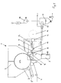
- FIG. 1 the diagram of a dust removal system a tissue machine
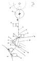
- Fig. 2 shows a detailed representation of each System elements
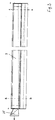
- Fig. 3 is a view of an upper disconnection box
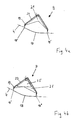
- FIG. 5 a view of a lower one Partition box
- Fig. 6a and 6b show sections through Fig. 5.
- Fig. 1 shows the scheme of dust removal from a paper web.
- the paper dryer 1 is located a drying cylinder 2 and a drying hood 3, from which hot air the paper web 4 guided around the drying cylinder 2 is blown.
- the At the entrance the paper web is still guided over pressure rollers 5, 5 '.
- To the paper web 4 is dried by means of a scraper 6 scraped off the drying cylinder 2.
- this creates a large one Amount of dust on the other hand, fibers are easily removed from the Paper surface lifted off.
- this stabilizer 8 can be lowered fold, so that afterwards the paper web is listed again without problems can be.
- an air separation box 9 which further stabilization of the web and separates air from the top of the paper web. That there is then another disconnection box 10 on the underside the paper web into the dust-laden and carried on the bottom Air is deflected. Simply by the dynamic pressure of the air carried this has already been removed and hardly any extraction is required.
- Subsequent to the lower disconnection box 10 is usually located a traversing measuring device 11 for recording the paper web properties.
- Another separation box is for further dust separation 12 provided on the top of the paper web before the paper web is wound onto the drum 14 via a work roll 13. All with Dust-laden air streams are passed through a separator 15, in where the dust is separated by injecting water. The air is then sucked off by a fan 16, which with dust loaded water gets into a container 17 and from there as waste water is dissipated.
- Fig. 2 shows the part of the dust extraction in detail. It's the one here To detect drying cylinder 2, of which the paper web 4 by means of Scraper 6 is scraped off. Part of the dust-blown air is thereby through the pivotable stabilizer 8 down into the Committee 7 distracted. Then the paper becomes Disconnection box 9, which for stable paper web guidance has curved guide surface 18. The paper web runs here Inlet 18 'tangentially on this disconnection box 9 and leaves the Partition box at the outlet 18 "also tangential. Through this curved Guide surface 18 generates the required web tension, so that stable web guidance is always guaranteed. At the inlet 18 ' Air carried by the paper web is diverted and into a suction slot 19 out.
- the wall 20 of the suction slot 19 is articulated, whereby the suction slot 19 is adjustable. To clean the Disconnect box, this wall 20 can be folded all the way up and thus the suction channel 21 are released for cleaning.
- the inner surfaces of the disconnect box are smooth and have no edges, corners or other places where dust can accumulate. That too cleaning of the junction box is made easier.
- the paper web comes under a small angle, preferably from 1 ° to 5 °, for example here from 1 ° to 2 °, which in turn ensures good web guidance.
- the entrained air is here in the box 10 via a suction slot 22 guided.
- This suction slot 22 has a baffle 23, which for optimal air separation is adjustable.
- At the outlet of the Paper web from the disconnect box 10 can be supplied to air Vortex formation and the associated new generation of dust Avoid occurrence of negative pressure.
- the web After passing the paper web by a traversing measuring device 11, the web is over another Disconnect box 12, which is analogous to the lower disconnect box 10 is executed. Subsequently, the paper web 4 on rollers 13 on the Reel 14 rolled up.
- Fig. 3 shows a view of an upper disconnect box 9, the left here Drive side (marked with TS) and on the right the so-called driver side (marked with FS) of the paper machine is marked.
- the air gets over a suction pipe 25 is discharged from the disconnection box 9 on the drive side.
- FIGS. 4a and 4b show a cross section of the disconnection box 9 in the vicinity according to the driver's side according to line A-A or near the drive side according to Line B-B. It can be seen here that the cross section of the suction channel 21 of the driver side increases towards the drive side. This ensures that the Speeds are almost constant in all points across the web width are. So there are no local differences in air extraction and the risk of web breaks is reduced. In Figures 4a and 4b the leadership of the paper web 4 is clearly visible, which over the Guide surface 18 of the disconnection box 9 is guided.
- the paper web 4 runs in and out tangentially and it is through the design of the inlet 18 'or the outlet 18 "is ensured, that there is no further dust generation by the deflection.
- the air from the boundary layer is through the suction slot 19 in the Collection channel 21 passed.
- the chamber wall 20 is designed to be pivotable, so that on the one hand the suction slot 19 can be adjusted and the furthermore the disconnection box 9 can be opened for cleaning.
- FIG. 5 now shows the view of a lower disconnection box 10, again the drive side on the left and the driver side of the paper machine on the right, whereby the suction takes place via a line 26, 27 on the drive side.
- FIG. 6a shows the cross section of the disconnect box 10 on the driver's side according to line C-C.
- the disconnect box 10 clearly visible.
- the air is through the baffle 23 passed into the disconnection box 10. More air can flow out the paper web 4 is sucked off from the separation box 10 through an opening 28 become.
- the cross section of the disconnect box 10 is on the Drive side shown according to line D-D.
- Suction cross sections 26 and 27 can be seen.
Abstract
Description
Die Erfindung betrifft ein Verfahren zur Staubabtrennung von einer laufenden Papierbahn, insbesondere Tissuebahn, wobei die mit der Papierbahn mitgeführte und staubbeladene Luft aus der Grenzschicht abgetrennt wird. Weiters betrifft die Erfindung eine Vorrichtung zur Durchführung des Verfahrens mit einem quer zur Papierbahn verlaufenden ersten Abtrennkasten.The invention relates to a method for separating dust from a running paper web, in particular tissue web, the with the Air entrained and dust-laden air from the boundary layer is separated. Furthermore, the invention relates to a device for Implementation of the process with a cross-web first disconnection box.
Bei Erzeugung von Tissuepapier können je nach Rohstoff, Produkt, Endtrockengehalt und Chemieeinsatz zwischen 1 bis 2% der Produktion als Staub im Bereich der Kreppung anfallen. Dieser Staub führt einerseits zur Beeinträchtigung der Produktion und stellt andererseits eine Gefahr für die Gesundheit und Sicherheit der Mitarbeiter dar. Durch den Trend zu weicheren Tissuepapieren und den Einsatz von mehr mechanischen Faserstoffen wird das Staubproblem noch vergrößert. Der Staub besteht aus Feinteilen und Fragmenten von Fasern, die von der Papierbahn primär beim Kreppschaber abgetrennt werden. Ein Teil des Staubes fällt auf den Boden des Maschinenraums und der Rest wird mit der Luftgrenzschicht an beiden Seiten der Papierbahn befördert, während sie vom Kreppschaber zum Roller transportiert wird. Ein weiterer Anteil von Staub verbleibt auf der Oberfläche der Papierbahn, wodurch es bei der Weiterbearbeitung zu Problemen kommen kann.When producing tissue paper, depending on the raw material, product, Final dry content and chemical use between 1 to 2% of production as Dust accumulates in the area of the crepe. On the one hand, this dust leads to Impairment of production and, on the other hand, poses a danger to the Health and safety of employees. By the trend to softer tissue paper and the use of more mechanical The dust problem is exacerbated by fibrous materials. The dust consists of Fine parts and fragments of fibers that come from the paper web primarily at Crepe scrapers are separated. Part of the dust falls on the floor of the engine room and the rest with the air boundary layer on both Sides of the paper web are conveyed while moving from the crepe doctor to the roller is transported. Another portion of dust remains on the surface the paper web, causing problems in further processing can come.
Ziel der Erfindung ist es, ein Verfahren und eine Vorrichtung zu schaffen, bei der der anfallende Staub auf einer sich schnell bewegenden Papierbahn, insbesondere Tissuebahn, so entfernt wird, daß die zulässigen Staubgrenzwerte eingehalten werden und dabei die Verfügbarkeit der Papiermaschine, insbesondere Tissuemaschine, verbessert wird. The aim of the invention is to provide a method and an apparatus for the dust accumulating on a fast moving paper web, especially tissue web, is removed so that the allowable Dust limit values are observed and the availability of the Paper machine, especially tissue machine, is improved.
Die Erfindung ist daher dadurch gekennzeichnet, daß die Papierbahn auf die gekrümmte Führungsfläche eines als Stabilisator ausgebildeten Abtrennkastens tangential auf- und abläuft und die Luft aus der Grenzschicht abgelenkt und durch den Abtrennkasten abgeführt wird. Durch den als Stabilisator ausgebildeten Abtrennkasten wird eine exakte Bahnführung erreicht, wobei das tangentiale Auf- und Ablaufen auf die gekrümmte Führungsfläche die Rißanfälligkeit der Papierbahn wesentlich herabsetzt. Dies wird weiters dadurch unterstützt, daß die Luft aus der Grenzschicht abgelenkt und in den Abtrennkasten geleitet und von dort weiter abgeführt wird. Die sonst üblichen Wirbel und Überdrücke, die ebenfalls zu Bahnabrissen führen, werden dadurch vermieden.The invention is therefore characterized in that the paper web on the curved guide surface designed as a stabilizer Disconnect box runs up and down tangentially and the air from the Boundary layer is deflected and discharged through the separation box. By the disconnect box, which is designed as a stabilizer, becomes an exact one Path guidance reached, the tangential running up and down on the curved guide surface significantly increases the susceptibility to tearing of the paper web belittles. This is further supported by the fact that the air from the Boundary layer deflected and directed into the disconnection box and from there is dissipated further. The usual swirls and pressures that This also prevents web breaks.
Eine günstige Weiterbildung der Erfindung ist dadurch gekennzeichnet, daß die Luft aus der Grenzschicht abgesaugt wird. Dadurch wird die Gefahr des Papierbahnabrisses durch einen Überdruck weiter herabgesetzt.A favorable development of the invention is characterized in that the air is extracted from the boundary layer. This will increase the risk of Paper web tear further reduced by overpressure.
Eine günstige Ausgestaltung der Erfindung ist dadurch gekennzeichnet, daß die Luft gleichmäßig über die Banhbreite abgeführt wird. Durch diese Maßnahme kann auch ein örtlicher Überdruck verhindert werden, der allenfalls bei sehr dünnen Papieren zu Abrissen führen könnte.A favorable embodiment of the invention is characterized in that the air is evacuated evenly across the width of the rail. Through this A local overpressure can also be prevented could lead to tears at most with very thin papers.
Eine vorteilhafte Weiterbildung der Erfindung ist dadurch gekennzeichnet, daß zusätzlich die Luft von der Unterseite der Papierbahn abgetrennt und abgeführt wird, wobei die von der Unterseite der Papierbahn abgetrennte Luft abgesaugt werden kann. Durch das Abtrennen bzw. Absaugen der Luft an der Unterseite wird auch der hier anhaftende Staub entfernt und abgeführt. Damit wird ermöglicht, daß die geforderten Staubgrenzwerte besser eingehalten werden können. An advantageous development of the invention is characterized in that that additionally the air is separated from the underside of the paper web and is removed, the one separated from the underside of the paper web Air can be extracted. By separating or sucking out the air the dust adhering to the bottom is also removed and dissipated. This enables the required dust limit values can be better adhered to.
Eine vorteilhafte Ausgestaltung der Erfindung ist dadurch gekennzeichnet, daß nach Abtrennung der staubbeladenen Luft Umgebungsluft zugeführt wird, um Wirbelbildung zu vermeiden. Um bei einer für die Staubentfernung ausreichenden Absaugung der Luft eine allfällige Wirbelbildung und damit verbundene Gefahr des Papierbahnabrisses zu vermeiden, wird an diesen Stellen staubfreie Umgebungsluft zugeführt und damit wieder der entsprechende Druck hergestellt.An advantageous embodiment of the invention is characterized in that that after separation of the dust-laden air ambient air is supplied to avoid vortex formation. To at one for dust removal sufficient suction of the air a possible vortex formation and thus To avoid the associated risk of paper web tear-off is at these Provide dust-free ambient air and thus the appropriate pressure produced.
Eine günstige Weiterbildung der Erfindung ist dadurch gekennzeichnet, daß die Papierbahn vor der Luftabtrennung stabilisiert wird, wobei mitgeschleppte Luft vom Stabilisator abgeleitet werden kann. Die zusätzliche Stabilisierung der Papierbahn vor der Luftabtrennung erleichtert die Bahnführung und verringert dadurch ebenfalls die Gefahr von Bahnabrissen. Wird mitgeschleppte Luft vom Stabilisator abgeleitet, kann bereits vor der eigentlichen Luftabtrennung ein Teil des Staubes entfernt werden.A favorable development of the invention is characterized in that the paper web is stabilized before the air separation, whereby entrained air can be discharged from the stabilizer. The additional Stabilizing the paper web before air separation makes it easier Web guidance and thereby also reduces the risk of web breaks. If entrained air is discharged from the stabilizer, the actual air separation, some of the dust can be removed.
Weiters betrifft die Erfindung eine Vorrichtung zur Staubabtrennung von einer laufenden Papierbahn, insbesondere Tissuebahn, mit einem quer zur Papierbahn verlaufenden ersten Abtrennkasten. Sie ist dadurch gekennzeichnet, daß der erste Abtrennkasten als Stabilisator mit gekrümmter Führungsfläche für die Papierbahn ausgebildet ist und eine Einrichtung zur Umlenkung der Luftgrenzschicht in einen Sammelkanal des Abtrennkastens aufweist. Durch die Form des Abtrennkastens als Stabilisator mit gekrümmter Führungsfläche wird eine gute Bahnführung erreicht und damit die Gefahr des Abrissses der Papierbahn verringert. Die gleichzeitige Abfuhr der Luftgrenzschicht in einen Sammelkanal ermöglicht eine gute Staubentfernung von der schnell laufenden Papierbahn.Furthermore, the invention relates to a device for dust separation from a running paper web, in particular tissue web, with one across Paper first trench box. It is through it characterized in that the first disconnection box as a stabilizer curved guide surface for the paper web and a Device for deflecting the air boundary layer into a collecting duct of the Disconnect box. Due to the shape of the disconnection box as Stabilizer with curved guide surface becomes a good web guide reached and thus reduces the risk of the paper web tearing. The allows simultaneous removal of the air boundary layer into a collecting duct a good dust removal from the fast running paper web.
Eine Weiterbildung der Erfindung ist dadurch gekennzeichnet, daß der Sammelkanal einen sich zur Triebseite der Maschine erweiternden Querschnitt aufweist. Dadurch wird erreicht, daß die Luft gleichmäßig über die Bahnbreite abgeführt wird, und somit kein örtlicher Über- oder Unterdruck entsteht, der zu Bahnabrissen führen kann.A further development of the invention is characterized in that the Collecting channel a widening to the drive side of the machine Has cross section. This ensures that the air is evenly above the web width is removed, and thus no local over or Negative pressure arises, which can lead to web breaks.
Eine vorteilhafte Ausgestaltung der Erfindung ist dadurch gekennzeichnet, daß an der Papierauflaufseite des ersten Abtrennkastens ein Absaugschlitz vorgesehen ist, der vorzugsweise einstellbar ausgeführt ist. Durch den vorgesehenen Absaugschlitz kann die Luft mit dem Staub gezielt abgeführt werden, wobei es die Einstellbarkeit ermöglicht die Menge entsprechend dem Anfall abzutrennen bzw. abzusaugen.An advantageous embodiment of the invention is characterized in that that a suction slot on the paper feed side of the first disconnect box is provided, which is preferably designed to be adjustable. By the provided suction slot, the air can be removed with the dust the adjustability allows the amount accordingly to separate or vacuum the seizure.
Eine günstige Weiterbildung der Erfindung ist dadurch gekennzeichnet, daß der Abtrennkasten auf der gesamten Breite öffenbar ist. Durch diese Ausführung wird eine günstige Reinigungsmöglichkeit geschaffen, die speziell bei der staubbeladenen Luft in feuchter Umgebung von Bedeutung ist.A favorable development of the invention is characterized in that the partition box can be opened across the entire width. Through this Execution creates an inexpensive cleaning option that Particularly important for dust-laden air in a humid environment is.
Eine vorteilhafte Ausgestaltung der Erfindung ist dadurch gekennzeichnet, daß ein weiterer Abtrennkasten an der Papierbahnunterseite vorgesehen ist, auf dem die Papierbahn mit einem sehr kleinen Winkel, vorzugsweise von 1° bis 5°, beispielsweise von 1° bis 2°, aufläuft. Durch einen weiteren Abtrennkasten an der Papierunterseite wird eine zusätzliche Staubentfernung ermöglicht, wobei das Auflaufen mit einem sehr kleinen Winkel in einfacher Weise eine bessere Bahnführung ermöglicht und somit zu weniger Abrissen an scharfen Kanten führt.An advantageous embodiment of the invention is characterized in that that a further separation box is provided on the underside of the paper web, on which the paper web with a very small angle, preferably from 1 ° to 5 °, for example from 1 ° to 2 °. Another one Disconnect box on the underside of the paper becomes an additional one Allows dust removal, with the emergence with a very small Angle enables better web guidance in a simple manner and thus leads to fewer tears on sharp edges.
Eine vorteilhafte Weiterbildung der Erfindung ist dadurch gekennzeichnet, daß der weitere Abtrennkasten ein Ablenkblech aufweist, das vorzugsweise schwenkbar ausgeführt ist. Mit diesem Ablenkblech kann die Luft direkt in den Abtrennkasten geleitet werden, wobei es die schwenkbare Ausführung ermöglicht, die abzutrennende Luftmenge einzustellen.An advantageous development of the invention is characterized in that that the further separation box has a baffle, which preferably is designed to be pivotable. With this baffle, the air can get in directly the disconnection box can be directed, being the swiveling version allows you to set the amount of air to be separated.
Eine günstige Ausgestaltung der Erfindung ist dadurch gekennzeichnet, daß der untere Abtrennkasten mindestens in zwei Kammern geteilt ist. Durch diese Ausführung läßt sich die Luft vor und hinter dem Abtrennkasten gesondert abführen und auch die Abführmenge gesondert einstellen, sodaß eine stabile Bahnführung ohne Abrisse gewährleistet wird.A favorable embodiment of the invention is characterized in that the lower disconnection box is divided into at least two chambers. By this version allows the air in front of and behind the disconnection box separate and also adjust the amount to be removed separately so that stable web guidance without tears is guaranteed.
Eine günstige Weiterbildung der Erfindung ist dadurch gekennzeichnet, daß ein Stabilisator vor dem ersten Abtrennkasten vorgesehen ist, der eine Breitstreckwirkung auf die Papierbahn ausübt, wobei der Stabilisator schwenkbar ausgeführt sein kann. Durch diesen zusätzliche Stabilisator wird eine noch stabilere Bahnführung erzielt, wobei zusätzlich eine Luftablenkung und damit Staubreduzierung erfolgt. Durch die schwenkbare Ausführung ist immer die ideale Bahnspannung gewährleistet und auch bei Bahnabrissen kann dieser Stabilisator vor dem Aufführen der Papierbahn weggeklappt werden.A favorable development of the invention is characterized in that a stabilizer is provided in front of the first disconnection box, the one Spreader effect on the paper web, the stabilizer can be pivoted. With this additional stabilizer achieves an even more stable web guidance, with additional air deflection and thus dust reduction. Due to the swivel design The ideal web tension is always guaranteed and also in the event of web breaks this stabilizer can be folded away before the paper web is listed become.
Eine vorteilhafte Weiterbildung der Erfindung ist dadurch gekennzeichnet, daß im Bereich des Schabers der Papiermaschine auf der Triebseite eine trichterförmige Absaughaube vorgesehen ist. Durch eine derartige Absaugmöglichkeit kann auch während eines Bahnabrisses und Neuaufführen der Papierbahn der beim Schaber enstehende Staub sicher abgeführt werden und damit die Staubbelastung reduziert werden.An advantageous development of the invention is characterized in that that in the area of the scraper of the paper machine on the drive side funnel-shaped suction hood is provided. By such Suction can also be done during a web break and Reloading the paper web the dust generated by the scraper safely be dissipated and thus the dust pollution can be reduced.
Eine vorteilhafte Ausgestaltung der Erfindung ist dadurch gekennzeichnet, daß ein weiterer Abtrennkasten auf der Papieroberseite vorgesehen ist. Durch diese Maßnahme können auch noch die letzten Reste des noch an der Papierbahnoberseite anhaftenden Staubes entfernt werden, bevor die Papierbahn aufgerollt wird.An advantageous embodiment of the invention is characterized in that that another separation box is provided on the top of the paper. This measure also allows the last remnants of of the paper web adhering dust are removed before the Paper web is rolled up.
Im folgenden wird nun die Erfindung anhand der Zeichnungen beispielhaft beschrieben, wobei Fig. 1 das Schema eines Staubentfernungssystemes bei einer Tissuemaschine, Fig. 2 eine detaillierte Darstellung der einzelnen Systemelemente, Fig. 3 eine Ansicht eines oberen Abtrennkastens, Fig. 4a und 4b Schnitte durch Fig. 3, Fig. 5 eine Ansicht eines unteren Abtrennkastens und Fig. 6a und 6b Schnitte durch Fig. 5 zeigen.The invention will now be described by way of example with reference to the drawings 1, the diagram of a dust removal system a tissue machine, Fig. 2 shows a detailed representation of each System elements, Fig. 3 is a view of an upper disconnection box, Fig. 4a and 4b sections through FIG. 3, FIG. 5 a view of a lower one Partition box and Fig. 6a and 6b show sections through Fig. 5.
Fig. 1 zeigt das Schema einer Staubentfernung von einer Papierbahn. Am
Ende des Papierherstellungsprozeßes befindet sich der Papiertrockner 1 mit
einem Trockenzylinder 2 und einer Trockenhaube 3, aus der heiße Luft auf
die um den Trockenzylinder 2 geführte Papierbahn 4 geblasen wird. Die
Papierbahn wird am Eintritt noch über Anpreßwalzen 5, 5' geführt. Nach
erfolgter Trocknung der Papierbahn 4 wird diese mittels eines Schabers 6
vom Trockenzylinder 2 abgeschabt. Dabei entsteht einerseits eine große
Menge an Staub, andererseits werden Fasern leicht von der
Papieroberfläche abgehoben. Um im Falle eines Papierbahnabrisses das
Papier zu sammeln und nochmals verwenden zu können befindet sich
unterhalb des Schabers 6 eine sogenannte Ausschußbütte 7. Zur besseren
Bahnführung ist nach dem Schaber 6 ein Stabilisator 8 vorgesehen. Ein Teil
der mitgeführten und mit Staub beladenen Luft prallt hier an den Stabilisator
und wird in die Ausschußbütte 7 geleitet, von wo diese Luft abgesaugt wird.
Im Fall eines Papierbahnabrisses läßt sich dieser Stabilisator 8 nach unten
klappen, sodaß nachher die Papierbahn wieder problemlos aufgeführt
werden kann. Im Anschluß an diesen Stabilisator 8 befindet sich an der
Papierbahnoberseite ein Luftabtrennkasten 9, der eine weitere Stabilisierung
der Bahn durchführt und Luft von der Papierbahnoberseite abtrennt. Daran
anschließend befindet sich ein weiterer Abtrennkasten 10 an der Unterseite
der Papierbahn in den die an der Unterseite mitgeführte und staubbeladene
Luft abgelenkt wird. Allein durch den Staudruck der mitgeführten Luft wird
diese bereits abgeführt und es ist kaum eine Absaugung erforderlich.
Anschließend an den unteren Abtrennkasten 10 befindet sich üblicherweise
ein traversierendes Meßgerät 11 zur Aufnahme der Papierbahneigenschaften.
Zu weiteren Staubabtrennung ist noch ein weiterer Abtrennkasten
12 an der Papierbahnoberseite vorgesehen, bevor die Papierbahn
über eine Arbeitswalze 13 auf den Tambour 14 aufgewickelt wird. Alle mit
Staub beladenen Luftströme werden über einen Abscheider 15 geführt, in
dem der Staub durch Eindüsen von Wasser abgeschieden wird. Die Luft
wird anschließend durch einen Ventilator 16 abgesaugt, wobei das mit Staub
beladene Wasser in einen Behälter 17 gelangt und von dort als Abwasser
abgeführt wird.Fig. 1 shows the scheme of dust removal from a paper web. At the
At the end of the paper production process, the paper dryer 1 is located
a drying cylinder 2 and a drying hood 3, from which hot air
the
Fig. 2 zeigt nun den Teil der Staubabsaugung im Detail. Es ist hier der
Trockenzylinder 2 zu erkennen, von dem die Papierbahn 4 mittels des
Schabers 6 abgeschabt wird. Ein Teil der staubbladenen Luft wird dabei
durch den schwenkbar ausgeführten Stabilisator 8 nach unten in die
Ausschußbütte 7 abgelenkt. Daran anschließend wird das Papier zum
Abtrennkasten 9 geführt, der zur stabilen Papierbahnführung eine
gekrümmte Führungsfläche 18 aufweist. Die Papierbahn läuft hier am
Einlauf 18' tangential auf diesen Abtrennkasten 9 auf und verläßt den
Abtrennkasten am Auslauf 18" ebenfalls tangential. Durch diese gekrümmte
Führungsfläche 18 wird die erforderliche Bahnspannung erzeugt, sodaß
immer eine stabile Bahnführung gewährleistet wird. Am Einlauf 18' wird die
von der Papierbahn mitgeführte Luft umgelenkt und in einen Absaugschlitz
19 geführt. Die Wand 20 des Absaugschlitzes 19 ist gelenkig angebracht,
wodurch der Absaugschlitz 19 einstellbar ist. Zur Reinigung des
Abtrennkastens kann diese Wand 20 ganz nach oben geklappt und somit
der Absaugkanal 21 zur Reinigung freigegeben werden. Die Innenflächen
des Abtrennkastens sind glatt und weisen keine Kanten, Ecken oder
sonstige Stellen auf, an denen sich Staub ansammeln kann. Auch dadurch
wird eine Reinigung des Abtrennkastens erleichtert. Nach dem Ablaufen der
Papierbahn vom Auslauf 18" des Abtrennkastens 19 wird die Papierbahn 4
zu einem unteren Abtrennkasten 10 geführt. Hier trifft die Papierbahn unter
einem geringen Winkel, vorzugsweise von 1° bis 5°, beispielsweise hier von
1° bis 2°, auf, wodurch wiederum eine gute Bahnführung erreicht wird. Die
mitgeschleppte Luft wird hier über einen Absaugschlitz 22 in den Kasten 10
geführt. Dieser Absaugschlitz 22 weist ein Ablenkblech 23 auf, das zur
optimalen Luftabtrennung einstellbar ausgeführt ist. Am Auslauf der
Papierbahn vom Abtrennkasten 10 kann Luft zugeführt werden, um eine
Wirbelbildung und damit verbunden neuerliche Staubgeneration durch
Auftreten von Unterdruck zu vermeiden. Nach Durchgang der Papierbahn
durch ein traversierendes Meßgerät 11 wird die Bahn über einen weiteren
Abtrennkasten 12 geführt, der analog dem unteren Abtrennkasten 10
ausgeführt ist. Anschließend wird die Papierbahn 4 über Walzen 13 auf den
Tambour 14 aufgerollt.Fig. 2 shows the part of the dust extraction in detail. It's the one here
To detect drying cylinder 2, of which the
Fig. 3 zeigt eine Ansicht eines oberen Abtrennkastens 9, wobei hier links die
Triebseite (gekennzeichnet mit TS) und rechts die sogenannte Führerseite
(gekennzeichnet mit FS) der Papiermaschine markiert ist. Die Luft wird über
ein Absaugrohr 25 auf der Triebseite aus dem Abtrennkasten 9 abgeführt.Fig. 3 shows a view of an
Fig. 4a und 4b zeigen einen Querschnitt des Abtrennkastens 9 in der Nähe
der Führerseite gemäß Linie A-A bzw. in der Nähe der Triebseite gemäß
Linie B-B. Hier ist erkennbar, daß der Querschnitt des Absaugkanals 21 von
der Führerseite zur Triebseite hin zunimmt. Dadurch wird erreicht, daß die
Geschwindigkeiten in allen Punkten über die Bahnbreite annähernd konstant
sind. Somit treten keine örtlichen Unterschiede bei der Luftabsaugung auf
und die Gefahr von Bahnabrissen wird verringert. In den Figuren 4a und 4b
ist deutlich die Führung der Papierbahn 4 erkennbar, die über die
Führungsfläche 18 des Abtrennkastens 9 geführt wird. Am Eintritt 18' bzw.
Auslauf 18" läuft die Papierbahn 4 tangential ein bzw. ab und es wird durch
die Ausgestaltung des Einlaufes 18' bzw. des Auslaufes 18" sichergestellt,
daß es zu keiner weiteren Staubgenerierung durch die Umlenkung kommt.
Die Luft aus der Grenzschicht wird durch den Absaugschlitz 19 in den
Sammelkanal 21 geleitet. Die Kammerwand 20 ist schwenkbar ausgeführt,
sodaß einerseits der Absaugschlitz 19 eingestellt werden kann und des
weiteren auch der Abtrennkasten 9 zur Reinigung öffenbar ist.4a and 4b show a cross section of the
Fig. 5 zeigt nun die Ansicht eines unteren Abtrennkastens 10, wiederum
links die Triebseite und rechts die Führerseite der Papiermaschine, wobei
die Absaugung über eine Leitung 26, 27 auf der Triebseite erfolgt.5 now shows the view of a
Fig. 6a zeigt den Querschnitt des Abtrennkastens 10 auf der Führerseite
gemäß Linie C-C. Hier ist das nahezu ebene Auflaufen der Papierbahn 4 auf
den Abtrennkasten 10 gut erkennbar. Die Luft wird durch das Ablenkblech
23 in den Abtrennkasten 10 geleitet. Weitere Luft kann beim Ablaufen
der Papierbahn 4 vom Abtrennkasten 10 durch eine Öffnung 28 abgesaugt
werden. In Fig. 6b ist der Querschnitt des Abtrennkasten 10 auf der
Triebseite gemäß Linie D-D dargestellt. Hier sind zusätzlich die
Absaugquerschnitte 26 und 27 zu erkennen.6a shows the cross section of the
Die Erfindung ist nicht auf die dargestellten Ausführungsformen beschränkt.The invention is not restricted to the illustrated embodiments.
Claims (19)
Applications Claiming Priority (2)
| Application Number | Priority Date | Filing Date | Title |
|---|---|---|---|
| AT195099 | 1999-11-18 | ||
| AT0195099A AT408462B (en) | 1999-11-18 | 1999-11-18 | METHOD AND DEVICE FOR SEPARATING DUST FROM A RUNNING PAPER |
Publications (2)
| Publication Number | Publication Date |
|---|---|
| EP1101863A2 true EP1101863A2 (en) | 2001-05-23 |
| EP1101863A3 EP1101863A3 (en) | 2003-07-02 |
Family
ID=3524556
Family Applications (1)
| Application Number | Title | Priority Date | Filing Date |
|---|---|---|---|
| EP00124067A Pending EP1101863A3 (en) | 1999-11-18 | 2000-11-06 | Method and device for removing dust from a moving paper web |
Country Status (5)
| Country | Link |
|---|---|
| US (1) | US6457204B1 (en) |
| EP (1) | EP1101863A3 (en) |
| AT (1) | AT408462B (en) |
| BR (1) | BR0005439A (en) |
| CA (1) | CA2325507A1 (en) |
Cited By (3)
| Publication number | Priority date | Publication date | Assignee | Title |
|---|---|---|---|---|
| EP1731670A1 (en) * | 2005-06-10 | 2006-12-13 | Milltech S.r.l. | Cleaning apparatus, especially for paper production plants |
| EP1746207A2 (en) * | 2005-07-22 | 2007-01-24 | Milltech S.r.l. | Stabilizing apparatus for paper webs in the course of formation |
| CN106780983A (en) * | 2017-01-20 | 2017-05-31 | 华南师范大学 | A kind of bank note treatment device with dust arrester |
Families Citing this family (8)
| Publication number | Priority date | Publication date | Assignee | Title |
|---|---|---|---|---|
| DE102010056576B8 (en) | 2010-12-30 | 2015-05-07 | Paprima Industries Inc. | Papermaking machine and method of making paper |
| US8657998B2 (en) | 2011-06-17 | 2014-02-25 | The Procter & Gamble Company | Method and apparatus for particulate removal from moving paper webs |
| US9108229B2 (en) | 2011-06-17 | 2015-08-18 | The Procter & Gamble Company | Method and apparatus for particulate removal from moving paper webs |
| CN110479697B (en) * | 2019-08-19 | 2021-10-19 | 河南宝合元汽车配件有限公司 | Waste material cleaning equipment |
| CN112779811B (en) * | 2021-01-29 | 2022-10-04 | 恒安(重庆)生活用纸有限公司 | Positive wind pressure device for paper machine operation room |
| CN113787027B (en) * | 2021-09-16 | 2023-07-11 | 湖南财政经济学院 | Dust collection and cleaning device for calculator |
| CN114405896B (en) * | 2022-01-20 | 2022-11-15 | 江苏凯华铝业有限公司 | Embossing aluminum plate surface pattern rolling processing method |
| CN117206313B (en) * | 2023-11-08 | 2024-01-02 | 中建三局集团(深圳)有限公司 | Intelligent recycling equipment for building waste timber |
Citations (4)
| Publication number | Priority date | Publication date | Assignee | Title |
|---|---|---|---|---|
| EP0310161A1 (en) * | 1987-10-01 | 1989-04-05 | Valmet Paper Machinery Inc. | Method and apparatus for extracting dust that is released when creping off a paper web |
| EP0646422A1 (en) * | 1993-10-01 | 1995-04-05 | James River Corporation Of Virginia | Web cleaner apparatus and method |
| US5800679A (en) * | 1996-10-25 | 1998-09-01 | Valmet Corporation | Device in a paper machine or in a finishing device of a paper machine for removing dust |
| US5878462A (en) * | 1996-05-21 | 1999-03-09 | Valmet-Karlstad Ab | Dust removal apparatus |
Family Cites Families (6)
| Publication number | Priority date | Publication date | Assignee | Title |
|---|---|---|---|---|
| US5291628A (en) * | 1991-12-12 | 1994-03-08 | Xerox Corporation | High velocity air cleaner |
| JP2820599B2 (en) * | 1993-08-31 | 1998-11-05 | 株式会社伸興 | Dust removal device |
| US5490300A (en) * | 1994-04-25 | 1996-02-13 | Horn; Paul E. | Air amplifier web cleaning system |
| US5836044A (en) * | 1995-05-26 | 1998-11-17 | Chapman Corporation | Surface cleaner and collector system |
| US6148831A (en) * | 1996-10-25 | 2000-11-21 | Valmet Corporation | Method for cleaning a web |
| DE19726897C2 (en) * | 1997-06-25 | 2000-01-13 | Voith Sulzer Papiermasch Gmbh | Process for cleaning a conveyor belt |
-
1999
- 1999-11-18 AT AT0195099A patent/AT408462B/en not_active IP Right Cessation
-
2000
- 2000-11-06 EP EP00124067A patent/EP1101863A3/en active Pending
- 2000-11-08 CA CA002325507A patent/CA2325507A1/en not_active Abandoned
- 2000-11-14 US US09/712,755 patent/US6457204B1/en not_active Expired - Fee Related
- 2000-11-17 BR BR0005439-9A patent/BR0005439A/en active Search and Examination
Patent Citations (4)
| Publication number | Priority date | Publication date | Assignee | Title |
|---|---|---|---|---|
| EP0310161A1 (en) * | 1987-10-01 | 1989-04-05 | Valmet Paper Machinery Inc. | Method and apparatus for extracting dust that is released when creping off a paper web |
| EP0646422A1 (en) * | 1993-10-01 | 1995-04-05 | James River Corporation Of Virginia | Web cleaner apparatus and method |
| US5878462A (en) * | 1996-05-21 | 1999-03-09 | Valmet-Karlstad Ab | Dust removal apparatus |
| US5800679A (en) * | 1996-10-25 | 1998-09-01 | Valmet Corporation | Device in a paper machine or in a finishing device of a paper machine for removing dust |
Cited By (4)
| Publication number | Priority date | Publication date | Assignee | Title |
|---|---|---|---|---|
| EP1731670A1 (en) * | 2005-06-10 | 2006-12-13 | Milltech S.r.l. | Cleaning apparatus, especially for paper production plants |
| EP1746207A2 (en) * | 2005-07-22 | 2007-01-24 | Milltech S.r.l. | Stabilizing apparatus for paper webs in the course of formation |
| EP1746207A3 (en) * | 2005-07-22 | 2007-07-04 | Milltech S.r.l. | Stabilizing apparatus for paper webs in the course of formation |
| CN106780983A (en) * | 2017-01-20 | 2017-05-31 | 华南师范大学 | A kind of bank note treatment device with dust arrester |
Also Published As
| Publication number | Publication date |
|---|---|
| CA2325507A1 (en) | 2001-05-18 |
| ATA195099A (en) | 2001-04-15 |
| AT408462B (en) | 2001-12-27 |
| US6457204B1 (en) | 2002-10-01 |
| EP1101863A3 (en) | 2003-07-02 |
| BR0005439A (en) | 2001-07-31 |
Similar Documents
| Publication | Publication Date | Title |
|---|---|---|
| EP0509199B2 (en) | Press section for a papermachine | |
| AT508470B1 (en) | METHOD AND DEVICE FOR TRANSMITTING A FIBER TRAIN FROM ONE SUPPORT FABRIC TO ANOTHER | |
| AT408462B (en) | METHOD AND DEVICE FOR SEPARATING DUST FROM A RUNNING PAPER | |
| DE3344217C2 (en) | ||
| EP0824158B1 (en) | Apparatus for drying a fibrous web | |
| DE4314475A1 (en) | Paper web passage through drying section - has sealing bar structure at deflection roller for roller surface recesses to generate underpressure without roller suction | |
| DE2920713A1 (en) | METHOD AND DEVICE FOR REMOVING A TRAIL FROM THE TRAINING SCREEN AND TRANSFERRING IT TO A CLOTH OF THE PRESS SECTION OF A PAPER MACHINE | |
| DE4121432A1 (en) | DEVICE FOR MEASURING THE CONDITION OF A FELT AND REPAIRING THE FELT | |
| EP1072722B1 (en) | Dryer section | |
| DE3400939C2 (en) | ||
| EP1285991A2 (en) | Device for treating a fibrous web | |
| EP1354677A2 (en) | Water-jet cutting device | |
| DE3800669C2 (en) | ||
| DE3731541C2 (en) | Method and device for the stabilized guidance of a moving material web | |
| DE19636791A1 (en) | Method and device for removing paper web remnants from a belt | |
| DE102014225262A1 (en) | Edge strip-cutting device | |
| DE102007024322A1 (en) | Transferring defective paper or cardboard sheet into rejection system of production machine, by stripping from supporting fabric using transfer fabric rising at an angle above transfer device | |
| DE4335024C2 (en) | Press section of a paper machine and transfer device | |
| EP4038235B1 (en) | Device and method for applying process air | |
| AT520935B1 (en) | Device and method for transferring a strip | |
| WO1995020068A1 (en) | Traction-free web transport in a compression section | |
| DE102007043087A1 (en) | Transfer of paper web between supporting felts, is achieved by suction unit directed to guide roller location on side opposite suction unit location | |
| DE102004042637A1 (en) | Cutting station for wet web of paper, tissue paper or carton has sliding blade mounted on transverse retractable rail | |
| DE19922428B4 (en) | Screen drum device | |
| AT506989B1 (en) | METHOD AND APPARATUS FOR CARRYING OUT A SEILED TRAIN INTRODUCTION |
Legal Events
| Date | Code | Title | Description |
|---|---|---|---|
| PUAI | Public reference made under article 153(3) epc to a published international application that has entered the european phase |
Free format text: ORIGINAL CODE: 0009012 |
|
| AK | Designated contracting states |
Kind code of ref document: A2 Designated state(s): AT BE CH CY DE DK ES FI FR GB GR IE IT LI LU MC NL PT SE TR |
|
| AX | Request for extension of the european patent |
Free format text: AL;LT;LV;MK;RO;SI |
|
| PUAL | Search report despatched |
Free format text: ORIGINAL CODE: 0009013 |
|
| AK | Designated contracting states |
Designated state(s): AT BE CH CY DE DK ES FI FR GB GR IE IT LI LU MC NL PT SE TR |
|
| AX | Request for extension of the european patent |
Extension state: AL LT LV MK RO SI |
|
| 17P | Request for examination filed |
Effective date: 20031009 |
|
| AKX | Designation fees paid |
Designated state(s): AT BE CH CY DE DK ES FI FR GB GR IE IT LI LU MC NL PT SE TR |
|
| 18W | Application withdrawn |
Effective date: 20090603 |
|
| STAA | Information on the status of an ep patent application or granted ep patent |
Free format text: STATUS: THE APPLICATION IS DEEMED TO BE WITHDRAWN |
|
| 18D | Application deemed to be withdrawn |
Effective date: 20090603 |
|
| D18W | Application withdrawn (deleted) |