EP1101667B1 - Zünder - Google Patents
Zünder Download PDFInfo
- Publication number
- EP1101667B1 EP1101667B1 EP00124126A EP00124126A EP1101667B1 EP 1101667 B1 EP1101667 B1 EP 1101667B1 EP 00124126 A EP00124126 A EP 00124126A EP 00124126 A EP00124126 A EP 00124126A EP 1101667 B1 EP1101667 B1 EP 1101667B1
- Authority
- EP
- European Patent Office
- Prior art keywords
- igniter
- metallised
- mid carrier
- electronic components
- mid
- Prior art date
- Legal status (The legal status is an assumption and is not a legal conclusion. Google has not performed a legal analysis and makes no representation as to the accuracy of the status listed.)
- Expired - Lifetime
Links
Images

Classifications
-
- F—MECHANICAL ENGINEERING; LIGHTING; HEATING; WEAPONS; BLASTING
- F42—AMMUNITION; BLASTING
- F42B—EXPLOSIVE CHARGES, e.g. FOR BLASTING, FIREWORKS, AMMUNITION
- F42B3/00—Blasting cartridges, i.e. case and explosive
- F42B3/10—Initiators therefor
- F42B3/12—Bridge initiators
- F42B3/121—Initiators with incorporated integrated circuit
-
- B—PERFORMING OPERATIONS; TRANSPORTING
- B60—VEHICLES IN GENERAL
- B60R—VEHICLES, VEHICLE FITTINGS, OR VEHICLE PARTS, NOT OTHERWISE PROVIDED FOR
- B60R21/00—Arrangements or fittings on vehicles for protecting or preventing injuries to occupants or pedestrians in case of accidents or other traffic risks
- B60R21/02—Occupant safety arrangements or fittings, e.g. crash pads
- B60R21/16—Inflatable occupant restraints or confinements designed to inflate upon impact or impending impact, e.g. air bags
- B60R21/26—Inflatable occupant restraints or confinements designed to inflate upon impact or impending impact, e.g. air bags characterised by the inflation fluid source or means to control inflation fluid flow
-
- B—PERFORMING OPERATIONS; TRANSPORTING
- B29—WORKING OF PLASTICS; WORKING OF SUBSTANCES IN A PLASTIC STATE IN GENERAL
- B29L—INDEXING SCHEME ASSOCIATED WITH SUBCLASS B29C, RELATING TO PARTICULAR ARTICLES
- B29L2031/00—Other particular articles
- B29L2031/34—Electrical apparatus, e.g. sparking plugs or parts thereof
- B29L2031/3493—Moulded interconnect devices, i.e. moulded articles provided with integrated circuit traces
-
- B—PERFORMING OPERATIONS; TRANSPORTING
- B60—VEHICLES IN GENERAL
- B60R—VEHICLES, VEHICLE FITTINGS, OR VEHICLE PARTS, NOT OTHERWISE PROVIDED FOR
- B60R21/00—Arrangements or fittings on vehicles for protecting or preventing injuries to occupants or pedestrians in case of accidents or other traffic risks
- B60R21/02—Occupant safety arrangements or fittings, e.g. crash pads
- B60R21/16—Inflatable occupant restraints or confinements designed to inflate upon impact or impending impact, e.g. air bags
- B60R21/26—Inflatable occupant restraints or confinements designed to inflate upon impact or impending impact, e.g. air bags characterised by the inflation fluid source or means to control inflation fluid flow
- B60R2021/26029—Ignitors
-
- B—PERFORMING OPERATIONS; TRANSPORTING
- B60—VEHICLES IN GENERAL
- B60R—VEHICLES, VEHICLE FITTINGS, OR VEHICLE PARTS, NOT OTHERWISE PROVIDED FOR
- B60R21/00—Arrangements or fittings on vehicles for protecting or preventing injuries to occupants or pedestrians in case of accidents or other traffic risks
- B60R21/02—Occupant safety arrangements or fittings, e.g. crash pads
- B60R21/16—Inflatable occupant restraints or confinements designed to inflate upon impact or impending impact, e.g. air bags
- B60R21/26—Inflatable occupant restraints or confinements designed to inflate upon impact or impending impact, e.g. air bags characterised by the inflation fluid source or means to control inflation fluid flow
- B60R21/264—Inflatable occupant restraints or confinements designed to inflate upon impact or impending impact, e.g. air bags characterised by the inflation fluid source or means to control inflation fluid flow using instantaneous generation of gas, e.g. pyrotechnic
- B60R21/2644—Inflatable occupant restraints or confinements designed to inflate upon impact or impending impact, e.g. air bags characterised by the inflation fluid source or means to control inflation fluid flow using instantaneous generation of gas, e.g. pyrotechnic using only solid reacting substances, e.g. pellets, powder
Definitions
- the invention relates to an igniter for triggering a restraint, in particular a belt tensioner or airbags, in a motor vehicle, in the area at its front end a firing device such as a squib or an in a powder filled powder chamber arranged ignition resistance and includes electronic components which are arranged on an MID carrier.
- a firing device such as a squib or an in a powder filled powder chamber arranged ignition resistance and includes electronic components which are arranged on an MID carrier.
- An in a drive device of a restraining means of a motor vehicle built-in detonator is known for example from AT 000 522 U1.
- AT 000 522 U1 An in a drive device of a restraining means of a motor vehicle built-in detonator is known for example from AT 000 522 U1.
- inductors provided with the lead wires of the igniter are soldered free to supply the ignition energy and injected in plastic or cast in.
- these are relatively robust components such as inductors.
- an igniter of the type mentioned which also includes semiconductor devices in the form of integrated circuits be used.
- MID "molded interconnect device”
- Such carriers are produced, for example, in a two-stage injection molding process, wherein a base body made of a first plastic component with another Plastic component is encapsulated and one of the two plastic components via an electrochemical electroplating process with a superficial Metallization is foreseeable while the other of the two plastic components does not accept such galvanic metallization.
- the galvanic Metallizations are used to form printed conductors, which are on the MID carrier Contact and connect electronic components to be applied.
- the igniter body is formed by an MID carrier is, are pins as well as Zündanschlußstatte each at least partially embedded in the MID carrier and then connected to it insoluble.
- the object of the invention is an improved igniter of the aforementioned To provide type, its preparation over that of DE-A-19610799 known igniter is simplified. This is achieved by a Igniter with the features of claim 1.
- the pin (s) are thus connected to the pin Contacting of the igniter in the production of the MID carrier injected and are provided with appropriate galvanic metallizations, which the Form contact surfaces.
- the igniter according to the invention Furthermore, at least a part of the wall of the powder chamber also during production the MID carrier injected and is integrally formed with this.
- This further plastic component may be formed by a plastic soft component, of the formed around the outer periphery of the igniter circumferential sealing bead becomes.
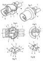
- the igniter according to the invention shown in FIGS. 1 to 8 has an MID carrier 1, on which electronic components are arranged, some of which are provided with the reference numeral 2. These electronic components 2 include et al Semiconductor devices in the form of integrated circuits. On In this way, a bus electronics can be formed for connecting the Igniter to a data bus system, above which commands to trigger the detonator are transferable.
- the MID carrier 1 comprises at least two plastic components used in a two-stage (or multi-stage) Injection molding are injection molded together.
- One of the plastic components is via an electrochemical galvanization process on its surface with Metallization foreseeable. These metallized areas can be used for training be used by printed conductors, which the electronic components. 2 contact and connect accordingly.
- Another plastic component is not about this electrochemical plating process metallizable and forms insulating areas on the surface of the MID carrier which, for example, between the by the galvanic metallizations lie formed tracks.
- Several metallized areas or insulating Areas on the surface of the MID carrier are in the figures with the reference numerals 5 and 6 provided.
- each of the pins 4 is thus at least on its surface partially covered by a metallization and metallized areas 5 with connected to the electronic components 2 in a corresponding manner.
- the igniter on a powder chamber 8, in a Ignition resistor 7 is arranged.
- the powder chamber is with an ignitable Powder (not shown in the figures) filled and is on its front over a membrane 9 closed.
- a lower part 10 of the side wall and the Rear wall 11 of the powder chamber are formed by the MID carrier.
- the ignition resistance 7 arranged and metallized areas 5 with the electronic Components 2 connected in a corresponding manner.
- the closure of the powder chamber on the front can also by a cap or be realized by an applied protective lacquer.
- a pyrotechnic material to be introduced into the powder chamber initially liquid, formed from two components to be mixed together pyrotechnic material are used, which hardens in the sequence.
- An additional front closure of the powder chamber can be omitted entirely.
- the cured pyrotechnic material is moisture resistant. such curable pyrotechnic materials are known. Also other pyrotechnic Materials of different consistency can be used here.
- the igniter according to the invention can furthermore be provided with a heat conducting device 3 be equipped.
- a heat conducting device 3 serves to increase the Transport safety of the detonator. It should be during the transport of the detonator to come to a fire accident, the case could occur that the detonator first is heated at its back. Without such a heat conducting device 3, the carrier of the igniter could become so unstable due to its heating, when, finally, the ignition of the powder enters the powder chamber 8, Parts of the housing could be thrown off.
- Longitudinal section is as a heat conduction from the area of the back End of the igniter provided in the powder chamber reaching metal pin. Additionally or instead, as shown in FIGS large-scale metallization of the surface of the MID carrier can be provided.
- large-area metallization is meant here that the metallized areas 5 of the surface of the MID carrier 1 take a much larger area as the intermediate insulating areas 6. This large area formed metallized areas 5 lead to a significant increase the thermal conductivity from the back of the igniter into the powder chamber 8. To further increase the thermal conductivity, one could turn from the back Area of the igniter extending into the powder chamber through be provided metallized area.
- a conventional squib 12 is provided in the further embodiment of the invention.
- their Connecting wires 13 are metallized areas on the surface of the MID carrier 1 connected.
- the encapsulation 14 with the further plastic component surrounds here also the rear portion of the squib 12.
- a heat conducting device 3 in the form of a metal pin extends from the area of rear end of the igniter to a lead wire 13 of the squib 12, with whom he communicates.
- Fig. 10 corresponds to the embodiment according to Fig. 1, but wherein the encapsulant surrounding the electronic components 16 was omitted. This succeeds without damaging the electronic components in the encapsulation by the application of an injection molding process with relatively low temperatures and pressures.
- plastic soft components 15 soft here as additional plastic component was sprayed onto the MID carrier.
- a bead 17 is formed, which the igniter surrounds along the outer periphery and acts as a seal when the fuze in a cylindrical connecting piece of a drive device for a retaining means is introduced in a motor vehicle. This seal becomes one Ingress of moisture into the propellant charge to be triggered by the igniter Drive device prevents.
- Figs. 11 and 12 further embodiments are at the rear end the MID carrier integral with the MID carrier formed pins shown.
- Fig. 11 is a single pin 4 provided, the plurality of metallized areas 5, each with intermediate has insulating regions 6.
- This with the electronic Components 2 are correspondingly associated metallized areas 5 via an attachable to the pin 4, with appropriate Maisfedem provided connector contacted.
- the terminal pins 4 trough-shaped, wherein in the trough-shaped depression of the pins. 4 each metallized areas 5 are formed.
- these trough-like areas of the Terminal pins 4 can be soldered connecting wires, which are at their opposite free ends in turn provided with appropriate plugs are.
- the trough-like pins 4 with the soldered leads 13 mitumspritzt conveniently.
- a housing cover could also be arranged on the MID carrier, which may possibly be potted.
- MID carrier produced by another known technique may be used.
Landscapes
- Engineering & Computer Science (AREA)
- Physics & Mathematics (AREA)
- Fluid Mechanics (AREA)
- Mechanical Engineering (AREA)
- Computer Hardware Design (AREA)
- Microelectronics & Electronic Packaging (AREA)
- General Engineering & Computer Science (AREA)
- Air Bags (AREA)
- Gears, Cams (AREA)
Description
- Fig. 1
- einen schematischen Längsschnitt durch ein erstes Ausführungsbeispiel der Erfindung;
- die Fig. 2 bis 5
- vergrößerte Darstellungen des MID-Trägers des Zünders von Fig. 1 in einer perspektivischen Ansicht von schräg oben, in einer Rückansicht, in einer Draufsicht und in einer Vorderansicht;
- die Fig. 6 bis 8
- verschiedene Stufen des Herstellungsprozesses des Zünders von Fig. 1 in einer perspektivischen Ansicht entsprechend der Fig. 2;
- die Fig. 9 und 10
- schematische Längsschnitte durch weitere Ausführungsbei spiele der Erfindung;
- die Fig. 11 und 12
- weitere Ausführungsformen von Anschlußstiften des Zünders.
- 1
- MID-Träger
- 2
- elektronischer Bauteil
- 3
- Wärmeleiteinrichtung
- 4
- Anschlußstift
- 5
- metallisierter Bereich
- 6
- isolierender Bereich
- 7
- Zündwiderstand
- 8
- Pulverkammer
- 9
- Membran
- 10
- Teil der Seitenwandung
- 11
- Rückwand
- 12
- Zündpille
- 13
- Anschlußdraht
- 14
- Umspritzung
- 15
- Kunststoffweichkomponente
- 16
- Vergußmasse
- 17
- Wulst
- 18
- Rückwand
Claims (10)
- Zünder zum Auslösen eines Rückhaltemittels, insbesondere eines Gurtstraffers oder Airbags, in einem Kraftfahrzeug, der im Bereich seines vorderen Endes eine Anzündeinrichtung wie eine Zündpille oder einen in einer mit Pulver befüllten Pulverkammer angeordneten Zündwiderstand sowie elektronische Bauteile umfaßt, die auf einem MID-Träger angeordnet sind, dadurch gekennzeichnet, dass der MID-Träger (1) zumindest einen aus einer galvanisch metallisierbaren Kunststoffkomponente bestehenden und einstückig mit dem MID-Träger (1) ausgebildeten Anschlußstift (4) aufweist, der zur Kontaktierung der elektronischen Bauteile (2) mit mindestens einem metallisierten Bereich (5) versehen ist.
- Zünder nach Anspruch 1, dadurch gekennzeichnet, dass zwei einstückig mit dem MID-Träger (1) ausgebildete Anschlußstifte (4) vorgesehen sind, die jeweils mit einem metallisierten Bereich (5) versehen sind.
- Zünder nach Anspruch 1, dadurch gekennzeichnet, dass ein einzelner Anschlußstift (4) vorgesehen ist, der zwei oder mehrere jeweils durch isolierende Bereiche (6) voneinander getrennte metallisierte Bereiche (5) zur Kontaktierung der elektronischen Bauteile (2) des Zünders aufweist.
- Zünder nach Anspruch 1, dadurch gekennzeichnet, dass zumindest ein Teil (10, 11 ) der Wandung der Pulverkammer (8) einstückig mit dem MID-Träger (1) ausgebildet ist.
- Zünder nach Anspruch 1, dadurch gekennzeichnet, dass an den mit den elektronischen Bauteilen (2) versehenen MID-Träger (1) eine weitere Kunststoffkomponente angespritzt ist.
- Zünder nach Anspruch 5, dadurch gekennzeichnet, dass die elektronischen Bauteile von der weiteren Kunststoffkomponente durch eine Vergußmasse (16) getrennt sind.
- Zünder nach Anspruch 5, dadurch gekennzeichnet, dass die weitere Kunststoffkomponente eine Kunststoffweichkomponente (15) ist, von der eine eine Dichtung darstellende, um die Außenseite des Zünders ringförmig umlaufende Wulst (17) gebildet wird.
- Zünder nach Anspruch 1, dadurch gekennzeichnet, dass die Fläche der metallisierten Bereiche (5) des MID-Trägers wesentlich größer als die Fläche der dazwischenliegenden isolierenden Bereiche (6) ist.
- Zünder nach Anspruch 1, dadurch gekennzeichnet, dass der MID-Träger (1) die vorzugsweise scheibenförmig ausgebildete Rückwand (11 ) der Pulverkammer (8) bildet, deren der Pulverkammer (8) zugewandte und/oder der Pulverkammer abgewandte Oberfläche zum Großteil, vorzugsweise zu mehr als 80 %, mit einem metallisierten Bereich (5) versehen ist.
- Zünder nach Anspruch 1, dadurch gekennzeichnet, dass die metallisierten Bereiche (5) in an sich bekannter Weise galvanisch metallisiert sind.
Priority Applications (1)
| Application Number | Priority Date | Filing Date | Title |
|---|---|---|---|
| AT00124126T ATE257103T1 (de) | 1999-11-22 | 2000-11-07 | Zünder |
Applications Claiming Priority (2)
| Application Number | Priority Date | Filing Date | Title |
|---|---|---|---|
| AT197899 | 1999-11-22 | ||
| AT197899 | 1999-11-22 |
Publications (3)
| Publication Number | Publication Date |
|---|---|
| EP1101667A2 EP1101667A2 (de) | 2001-05-23 |
| EP1101667A3 EP1101667A3 (de) | 2001-08-22 |
| EP1101667B1 true EP1101667B1 (de) | 2004-01-02 |
Family
ID=3525186
Family Applications (1)
| Application Number | Title | Priority Date | Filing Date |
|---|---|---|---|
| EP00124126A Expired - Lifetime EP1101667B1 (de) | 1999-11-22 | 2000-11-07 | Zünder |
Country Status (4)
| Country | Link |
|---|---|
| US (1) | US6463857B1 (de) |
| EP (1) | EP1101667B1 (de) |
| AT (1) | ATE257103T1 (de) |
| DE (1) | DE50004916D1 (de) |
Families Citing this family (7)
| Publication number | Priority date | Publication date | Assignee | Title |
|---|---|---|---|---|
| DE20309009U1 (de) | 2003-06-11 | 2003-08-14 | FESTO AG & Co., 73734 Esslingen | Elektrisches Bauteil, insbesondere Positionssensor |
| US7690303B2 (en) * | 2004-04-22 | 2010-04-06 | Reynolds Systems, Inc. | Plastic encapsulated energetic material initiation device |
| US8100043B1 (en) | 2008-03-28 | 2012-01-24 | Reynolds Systems, Inc. | Detonator cartridge and methods of use |
| US8276516B1 (en) | 2008-10-30 | 2012-10-02 | Reynolds Systems, Inc. | Apparatus for detonating a triaminotrinitrobenzene charge |
| US8485097B1 (en) | 2010-06-11 | 2013-07-16 | Reynolds Systems, Inc. | Energetic material initiation device |
| EP3735511B1 (de) | 2018-01-05 | 2023-03-29 | GeoDynamics, Inc. | Perforationspistolensystem und -verfahren |
| US12448875B2 (en) | 2022-02-08 | 2025-10-21 | Schlumberger Technology Corporation | Compact igniter |
Family Cites Families (16)
| Publication number | Priority date | Publication date | Assignee | Title |
|---|---|---|---|---|
| GB1489269A (en) * | 1974-12-20 | 1977-10-19 | Daimler Benz Ag | Ignition device for a stand-by gas-supply system |
| US5269560A (en) * | 1990-12-18 | 1993-12-14 | Twr Inc. | Initiator assembly for air bag inflator |
| DE4307774A1 (de) * | 1993-03-12 | 1994-09-15 | Dynamit Nobel Ag | Anzündeinrichtung |
| AT522U1 (de) | 1994-03-23 | 1995-12-27 | Hirtenberger Ag | Antriebsvorrichtung fuer rueckhaltesysteme in kraftfahrzeugen |
| ATE194249T1 (de) | 1994-09-23 | 2000-07-15 | Siemens Nv | Polymer stud grid array package |
| DE19610799C1 (de) | 1996-03-19 | 1997-09-04 | Siemens Ag | Zündeinrichtung zum Auslösen eines Rückhaltemittels in einem Kraftfahrzeug |
| US5882034A (en) * | 1996-05-02 | 1999-03-16 | Motorola, Inc. | Automobile airbag system |
| DE69725423T2 (de) * | 1996-08-12 | 2004-07-22 | Thomas & Betts International Inc., Memphis | Richtungsfreie zündpille-anschlusseinrichtung für kraftfahrzeug-luftsacksysteme |
| DE19712314A1 (de) * | 1997-03-24 | 1998-10-01 | Thomas & Betts Gmbh | Verbindung für die Zündeinrichtung von Airbag-Systemen in Kraftfahrzeugen |
| US6126197A (en) * | 1997-04-24 | 2000-10-03 | Talley Defense Systems, Inc. | Lightweight discoidal filterless air bag inflator |
| US6276953B1 (en) * | 1997-12-04 | 2001-08-21 | Thoma & Betts International, Inc. | Orientationless squib connector assembly for automotive air bag assemblies |
| US6073963A (en) * | 1998-03-19 | 2000-06-13 | Oea, Inc. | Initiator with injection molded insert member |
| DE19836280C1 (de) * | 1998-08-11 | 2000-05-11 | Telefunken Microelectron | Pyrotechnisches Anzündelement mit integrierter Elektronik, zum Auslösen eines Rückhaltesystems |
| DE19856325A1 (de) * | 1998-12-07 | 2000-06-15 | Bosch Gmbh Robert | Zündvorrichtung für Rückhaltemittel in einem Fahrzeug |
| US6166452A (en) * | 1999-01-20 | 2000-12-26 | Breed Automotive Technology, Inc. | Igniter |
| US6257617B1 (en) * | 1999-03-04 | 2001-07-10 | Trw Inc. | Air bag inflator with pressure regulation |
-
2000
- 2000-11-07 DE DE50004916T patent/DE50004916D1/de not_active Expired - Lifetime
- 2000-11-07 AT AT00124126T patent/ATE257103T1/de not_active IP Right Cessation
- 2000-11-07 EP EP00124126A patent/EP1101667B1/de not_active Expired - Lifetime
- 2000-11-17 US US09/715,939 patent/US6463857B1/en not_active Expired - Fee Related
Also Published As
| Publication number | Publication date |
|---|---|
| EP1101667A2 (de) | 2001-05-23 |
| US6463857B1 (en) | 2002-10-15 |
| DE50004916D1 (de) | 2004-02-05 |
| ATE257103T1 (de) | 2004-01-15 |
| EP1101667A3 (de) | 2001-08-22 |
Similar Documents
| Publication | Publication Date | Title |
|---|---|---|
| EP0888227B1 (de) | Zündeinrichtung zum auslösen eines rückhaltemittels in einem kraftfahrzeug | |
| DE69925403T2 (de) | Zünder für Aufblasvorrichtung mit Einsatzkörper | |
| DE60124374T2 (de) | Zünderkonstruktion mit Aktivierungsschaltung | |
| DE68928095T2 (de) | Verfahren zur Herstellung eines elektronischen Moduls und elektronisches Modul, hergestellt nach diesem Verfahren | |
| DE4230443C2 (de) | Zündvorrichtung mit Adapter | |
| EP2012082B1 (de) | Metall/Fixiermaterial-Sockel für Zündvorrichtungen von Airbags oder dergleichen Personenschutzeinrichtungen, insbesondere bei Kraftfahrzeugen sowie Zündvorrichtung mit einem derartigen Sockel | |
| DE69708196T2 (de) | Zünder mit selbstklemmendem Zweileiter-Anschluss für pyrotechnische Gasgeneratoren | |
| DE3904069A1 (de) | Wasserdichter stopfen fuer eine elektrische steckverbindung | |
| EP0904613B1 (de) | Steckverbinder mit einer mit elektrischen bauelementen bestückten leiterbahnstruktur sowie verfahren zur herstellung eines solchen | |
| DE3328114A1 (de) | Ausloesevorrichtung fuer rueckhaltesysteme in kraftfahrzeugen | |
| DE102008049404A1 (de) | Elektronische Schaltungsvorrichtung und Verfahren zur Herstellung derselben | |
| DE202006020901U1 (de) | Gasgenerator | |
| DE69807833T2 (de) | Elektro-pyrotechnischer Initialzünder mit drei elektrischen Verbindungen | |
| DE69330249T2 (de) | Leistungsverpackung mit hoher Zuverlässigkeit für eine elektronische Halbleiterschaltung | |
| EP1101667A2 (de) | Zünder | |
| DE102010039063B4 (de) | Sensormodul mit einem elektromagnetisch abgeschirmten elektrischen Bauteil und Verfahren zur Herstellung eines solchen Sensormoduls | |
| DE102008052399B4 (de) | Gasgenerator für eine Sicherheitseinrichtung in einem Fahrzeug | |
| EP0913882A2 (de) | Verfahren zum Isolieren eines elektrischen Bauteiles | |
| DE2655758A1 (de) | Pyrotechnische vorrichtung und verfahren zu deren herstellung | |
| EP1101668B1 (de) | Zünder | |
| DE69319082T2 (de) | Spritzgiessdüse mit einem elektrischen Anschlusselement mit isolierendem Stecker | |
| EP0983478A1 (de) | Zünder für einen pyrotechnischen gasgenerator und gasgenerator | |
| DE19940346B4 (de) | Piezoaktor mit einer Anschlußvorrichtung | |
| EP0806626A2 (de) | Elektrischer Zünder eines pyrotechnischen Gasgenerators | |
| EP3622589A1 (de) | Elektronikmodul und fertigungsverfahren |
Legal Events
| Date | Code | Title | Description |
|---|---|---|---|
| PUAI | Public reference made under article 153(3) epc to a published international application that has entered the european phase |
Free format text: ORIGINAL CODE: 0009012 |
|
| AK | Designated contracting states |
Kind code of ref document: A2 Designated state(s): AT BE CH CY DE DK ES FI FR GB GR IE IT LI LU MC NL PT SE TR |
|
| AX | Request for extension of the european patent |
Free format text: AL;LT;LV;MK;RO;SI |
|
| PUAL | Search report despatched |
Free format text: ORIGINAL CODE: 0009013 |
|
| AK | Designated contracting states |
Kind code of ref document: A3 Designated state(s): AT BE CH CY DE DK ES FI FR GB GR IE IT LI LU MC NL PT SE TR |
|
| AX | Request for extension of the european patent |
Free format text: AL;LT;LV;MK;RO;SI |
|
| RIC1 | Information provided on ipc code assigned before grant |
Free format text: 7B 60R 22/46 A, 7B 60R 21/26 B, 7B 60R 21/01 B |
|
| 17P | Request for examination filed |
Effective date: 20011213 |
|
| AKX | Designation fees paid |
Free format text: AT BE CH CY DE DK ES FI FR GB GR IE IT LI LU MC NL PT SE TR |
|
| 17Q | First examination report despatched |
Effective date: 20021211 |
|
| GRAH | Despatch of communication of intention to grant a patent |
Free format text: ORIGINAL CODE: EPIDOS IGRA |
|
| GRAS | Grant fee paid |
Free format text: ORIGINAL CODE: EPIDOSNIGR3 |
|
| GRAA | (expected) grant |
Free format text: ORIGINAL CODE: 0009210 |
|
| AK | Designated contracting states |
Kind code of ref document: B1 Designated state(s): AT BE CH CY DE DK ES FI FR GB GR IE IT LI LU MC NL PT SE TR |
|
| PG25 | Lapsed in a contracting state [announced via postgrant information from national office to epo] |
Ref country code: FI Free format text: LAPSE BECAUSE OF FAILURE TO SUBMIT A TRANSLATION OF THE DESCRIPTION OR TO PAY THE FEE WITHIN THE PRESCRIBED TIME-LIMIT Effective date: 20040102 Ref country code: TR Free format text: LAPSE BECAUSE OF FAILURE TO SUBMIT A TRANSLATION OF THE DESCRIPTION OR TO PAY THE FEE WITHIN THE PRESCRIBED TIME-LIMIT Effective date: 20040102 Ref country code: IE Free format text: LAPSE BECAUSE OF FAILURE TO SUBMIT A TRANSLATION OF THE DESCRIPTION OR TO PAY THE FEE WITHIN THE PRESCRIBED TIME-LIMIT Effective date: 20040102 Ref country code: CY Free format text: LAPSE BECAUSE OF FAILURE TO SUBMIT A TRANSLATION OF THE DESCRIPTION OR TO PAY THE FEE WITHIN THE PRESCRIBED TIME-LIMIT Effective date: 20040102 Ref country code: NL Free format text: LAPSE BECAUSE OF FAILURE TO SUBMIT A TRANSLATION OF THE DESCRIPTION OR TO PAY THE FEE WITHIN THE PRESCRIBED TIME-LIMIT Effective date: 20040102 |
|
| REG | Reference to a national code |
Ref country code: GB Ref legal event code: FG4D Free format text: NOT ENGLISH |
|
| REG | Reference to a national code |
Ref country code: CH Ref legal event code: EP |
|
| REG | Reference to a national code |
Ref country code: IE Ref legal event code: FG4D Free format text: GERMAN |
|
| REF | Corresponds to: |
Ref document number: 50004916 Country of ref document: DE Date of ref document: 20040205 Kind code of ref document: P |
|
| PG25 | Lapsed in a contracting state [announced via postgrant information from national office to epo] |
Ref country code: GR Free format text: LAPSE BECAUSE OF FAILURE TO SUBMIT A TRANSLATION OF THE DESCRIPTION OR TO PAY THE FEE WITHIN THE PRESCRIBED TIME-LIMIT Effective date: 20040402 Ref country code: SE Free format text: LAPSE BECAUSE OF FAILURE TO SUBMIT A TRANSLATION OF THE DESCRIPTION OR TO PAY THE FEE WITHIN THE PRESCRIBED TIME-LIMIT Effective date: 20040402 Ref country code: DK Free format text: LAPSE BECAUSE OF FAILURE TO SUBMIT A TRANSLATION OF THE DESCRIPTION OR TO PAY THE FEE WITHIN THE PRESCRIBED TIME-LIMIT Effective date: 20040402 |
|
| PG25 | Lapsed in a contracting state [announced via postgrant information from national office to epo] |
Ref country code: ES Free format text: LAPSE BECAUSE OF FAILURE TO SUBMIT A TRANSLATION OF THE DESCRIPTION OR TO PAY THE FEE WITHIN THE PRESCRIBED TIME-LIMIT Effective date: 20040413 |
|
| NLV1 | Nl: lapsed or annulled due to failure to fulfill the requirements of art. 29p and 29m of the patents act | ||
| GBT | Gb: translation of ep patent filed (gb section 77(6)(a)/1977) |
Effective date: 20040512 |
|
| RAP2 | Party data changed (patent owner data changed or rights of a patent transferred) |
Owner name: HIRSCHMANN AUTOMOTIVE GMBH |
|
| REG | Reference to a national code |
Ref country code: IE Ref legal event code: FD4D |
|
| ET | Fr: translation filed | ||
| PLBE | No opposition filed within time limit |
Free format text: ORIGINAL CODE: 0009261 |
|
| STAA | Information on the status of an ep patent application or granted ep patent |
Free format text: STATUS: NO OPPOSITION FILED WITHIN TIME LIMIT |
|
| PG25 | Lapsed in a contracting state [announced via postgrant information from national office to epo] |
Ref country code: AT Free format text: LAPSE BECAUSE OF NON-PAYMENT OF DUE FEES Effective date: 20041107 Ref country code: LU Free format text: LAPSE BECAUSE OF NON-PAYMENT OF DUE FEES Effective date: 20041107 |
|
| PG25 | Lapsed in a contracting state [announced via postgrant information from national office to epo] |
Ref country code: CH Free format text: LAPSE BECAUSE OF NON-PAYMENT OF DUE FEES Effective date: 20041130 Ref country code: MC Free format text: LAPSE BECAUSE OF NON-PAYMENT OF DUE FEES Effective date: 20041130 Ref country code: BE Free format text: LAPSE BECAUSE OF NON-PAYMENT OF DUE FEES Effective date: 20041130 Ref country code: LI Free format text: LAPSE BECAUSE OF NON-PAYMENT OF DUE FEES Effective date: 20041130 |
|
| 26N | No opposition filed |
Effective date: 20041005 |
|
| BERE | Be: lapsed |
Owner name: *HIRSCHMANN AUSTRIA G.M.B.H. Effective date: 20041130 |
|
| REG | Reference to a national code |
Ref country code: CH Ref legal event code: PL |
|
| PG25 | Lapsed in a contracting state [announced via postgrant information from national office to epo] |
Ref country code: IT Free format text: LAPSE BECAUSE OF NON-PAYMENT OF DUE FEES Effective date: 20051107 |
|
| BERE | Be: lapsed |
Owner name: *HIRSCHMANN AUSTRIA G.M.B.H. Effective date: 20041130 |
|
| PG25 | Lapsed in a contracting state [announced via postgrant information from national office to epo] |
Ref country code: PT Free format text: LAPSE BECAUSE OF NON-PAYMENT OF DUE FEES Effective date: 20040602 |
|
| PGFP | Annual fee paid to national office [announced via postgrant information from national office to epo] |
Ref country code: GB Payment date: 20071120 Year of fee payment: 8 |
|
| GBPC | Gb: european patent ceased through non-payment of renewal fee |
Effective date: 20081107 |
|
| REG | Reference to a national code |
Ref country code: FR Ref legal event code: TP Ref country code: FR Ref legal event code: CD |
|
| PG25 | Lapsed in a contracting state [announced via postgrant information from national office to epo] |
Ref country code: GB Free format text: LAPSE BECAUSE OF NON-PAYMENT OF DUE FEES Effective date: 20081107 |
|
| PGFP | Annual fee paid to national office [announced via postgrant information from national office to epo] |
Ref country code: DE Payment date: 20091120 Year of fee payment: 10 |
|
| PGFP | Annual fee paid to national office [announced via postgrant information from national office to epo] |
Ref country code: FR Payment date: 20091019 Year of fee payment: 10 |
|
| REG | Reference to a national code |
Ref country code: FR Ref legal event code: ST Effective date: 20110801 |
|
| REG | Reference to a national code |
Ref country code: DE Ref legal event code: R119 Ref document number: 50004916 Country of ref document: DE Effective date: 20110601 Ref country code: DE Ref legal event code: R119 Ref document number: 50004916 Country of ref document: DE Effective date: 20110531 |
|
| PG25 | Lapsed in a contracting state [announced via postgrant information from national office to epo] |
Ref country code: FR Free format text: LAPSE BECAUSE OF NON-PAYMENT OF DUE FEES Effective date: 20101130 |
|
| PG25 | Lapsed in a contracting state [announced via postgrant information from national office to epo] |
Ref country code: DE Free format text: LAPSE BECAUSE OF NON-PAYMENT OF DUE FEES Effective date: 20110531 |