EP1101667A2 - Allumeur - Google Patents
Allumeur Download PDFInfo
- Publication number
- EP1101667A2 EP1101667A2 EP00124126A EP00124126A EP1101667A2 EP 1101667 A2 EP1101667 A2 EP 1101667A2 EP 00124126 A EP00124126 A EP 00124126A EP 00124126 A EP00124126 A EP 00124126A EP 1101667 A2 EP1101667 A2 EP 1101667A2
- Authority
- EP
- European Patent Office
- Prior art keywords
- metallized
- detonator according
- electronic components
- mid carrier
- mid
- Prior art date
- Legal status (The legal status is an assumption and is not a legal conclusion. Google has not performed a legal analysis and makes no representation as to the accuracy of the status listed.)
- Granted
Links
- 239000000843 powder Substances 0.000 claims description 29
- 239000011324 bead Substances 0.000 claims description 4
- 150000001875 compounds Chemical class 0.000 claims description 4
- 238000005266 casting Methods 0.000 claims 1
- 238000001465 metallisation Methods 0.000 description 13
- 238000004519 manufacturing process Methods 0.000 description 7
- 238000000034 method Methods 0.000 description 7
- 239000000463 material Substances 0.000 description 5
- 239000004020 conductor Substances 0.000 description 4
- 238000005538 encapsulation Methods 0.000 description 4
- 239000000969 carrier Substances 0.000 description 3
- 238000009713 electroplating Methods 0.000 description 3
- 238000001746 injection moulding Methods 0.000 description 3
- 239000012528 membrane Substances 0.000 description 3
- 238000007789 sealing Methods 0.000 description 3
- 239000002184 metal Substances 0.000 description 2
- 230000035515 penetration Effects 0.000 description 2
- 238000004382 potting Methods 0.000 description 2
- 239000004065 semiconductor Substances 0.000 description 2
- ONBQEOIKXPHGMB-VBSBHUPXSA-N 1-[2-[(2s,3r,4s,5r)-3,4-dihydroxy-5-(hydroxymethyl)oxolan-2-yl]oxy-4,6-dihydroxyphenyl]-3-(4-hydroxyphenyl)propan-1-one Chemical compound O[C@@H]1[C@H](O)[C@@H](CO)O[C@H]1OC1=CC(O)=CC(O)=C1C(=O)CCC1=CC=C(O)C=C1 ONBQEOIKXPHGMB-VBSBHUPXSA-N 0.000 description 1
- 206010000369 Accident Diseases 0.000 description 1
- 238000010521 absorption reaction Methods 0.000 description 1
- 229940126142 compound 16 Drugs 0.000 description 1
- 238000009792 diffusion process Methods 0.000 description 1
- 230000008020 evaporation Effects 0.000 description 1
- 238000001704 evaporation Methods 0.000 description 1
- 238000010438 heat treatment Methods 0.000 description 1
- 238000003384 imaging method Methods 0.000 description 1
- 238000002347 injection Methods 0.000 description 1
- 239000007924 injection Substances 0.000 description 1
- 239000004922 lacquer Substances 0.000 description 1
- 239000007788 liquid Substances 0.000 description 1
- 230000000149 penetrating effect Effects 0.000 description 1
- 230000002265 prevention Effects 0.000 description 1
- 239000003380 propellant Substances 0.000 description 1
- 230000001681 protective effect Effects 0.000 description 1
Images
Classifications
-
- F—MECHANICAL ENGINEERING; LIGHTING; HEATING; WEAPONS; BLASTING
- F42—AMMUNITION; BLASTING
- F42B—EXPLOSIVE CHARGES, e.g. FOR BLASTING, FIREWORKS, AMMUNITION
- F42B3/00—Blasting cartridges, i.e. case and explosive
- F42B3/10—Initiators therefor
- F42B3/12—Bridge initiators
- F42B3/121—Initiators with incorporated integrated circuit
-
- B—PERFORMING OPERATIONS; TRANSPORTING
- B60—VEHICLES IN GENERAL
- B60R—VEHICLES, VEHICLE FITTINGS, OR VEHICLE PARTS, NOT OTHERWISE PROVIDED FOR
- B60R21/00—Arrangements or fittings on vehicles for protecting or preventing injuries to occupants or pedestrians in case of accidents or other traffic risks
- B60R21/02—Occupant safety arrangements or fittings, e.g. crash pads
- B60R21/16—Inflatable occupant restraints or confinements designed to inflate upon impact or impending impact, e.g. air bags
- B60R21/26—Inflatable occupant restraints or confinements designed to inflate upon impact or impending impact, e.g. air bags characterised by the inflation fluid source or means to control inflation fluid flow
-
- B—PERFORMING OPERATIONS; TRANSPORTING
- B29—WORKING OF PLASTICS; WORKING OF SUBSTANCES IN A PLASTIC STATE IN GENERAL
- B29L—INDEXING SCHEME ASSOCIATED WITH SUBCLASS B29C, RELATING TO PARTICULAR ARTICLES
- B29L2031/00—Other particular articles
- B29L2031/34—Electrical apparatus, e.g. sparking plugs or parts thereof
- B29L2031/3493—Moulded interconnect devices, i.e. moulded articles provided with integrated circuit traces
-
- B—PERFORMING OPERATIONS; TRANSPORTING
- B60—VEHICLES IN GENERAL
- B60R—VEHICLES, VEHICLE FITTINGS, OR VEHICLE PARTS, NOT OTHERWISE PROVIDED FOR
- B60R21/00—Arrangements or fittings on vehicles for protecting or preventing injuries to occupants or pedestrians in case of accidents or other traffic risks
- B60R21/02—Occupant safety arrangements or fittings, e.g. crash pads
- B60R21/16—Inflatable occupant restraints or confinements designed to inflate upon impact or impending impact, e.g. air bags
- B60R21/26—Inflatable occupant restraints or confinements designed to inflate upon impact or impending impact, e.g. air bags characterised by the inflation fluid source or means to control inflation fluid flow
- B60R2021/26029—Ignitors
-
- B—PERFORMING OPERATIONS; TRANSPORTING
- B60—VEHICLES IN GENERAL
- B60R—VEHICLES, VEHICLE FITTINGS, OR VEHICLE PARTS, NOT OTHERWISE PROVIDED FOR
- B60R21/00—Arrangements or fittings on vehicles for protecting or preventing injuries to occupants or pedestrians in case of accidents or other traffic risks
- B60R21/02—Occupant safety arrangements or fittings, e.g. crash pads
- B60R21/16—Inflatable occupant restraints or confinements designed to inflate upon impact or impending impact, e.g. air bags
- B60R21/26—Inflatable occupant restraints or confinements designed to inflate upon impact or impending impact, e.g. air bags characterised by the inflation fluid source or means to control inflation fluid flow
- B60R21/264—Inflatable occupant restraints or confinements designed to inflate upon impact or impending impact, e.g. air bags characterised by the inflation fluid source or means to control inflation fluid flow using instantaneous generation of gas, e.g. pyrotechnic
- B60R21/2644—Inflatable occupant restraints or confinements designed to inflate upon impact or impending impact, e.g. air bags characterised by the inflation fluid source or means to control inflation fluid flow using instantaneous generation of gas, e.g. pyrotechnic using only solid reacting substances, e.g. pellets, powder
Definitions
- the invention relates to an igniter for triggering a restraint, in particular a belt tensioner or airbag, in a motor vehicle operating in the area an ignition device such as a squib or an in its front end an ignition resistor arranged with powder filled powder chamber and comprises electronic components which are arranged on a MID carrier.
- an ignition device such as a squib or an in its front end an ignition resistor arranged with powder filled powder chamber and comprises electronic components which are arranged on a MID carrier.
- MID "molded interconnect device"
- Carriers are manufactured, for example, in a two-stage injection molding process, wherein a base body made of a first plastic component with a another plastic component is encapsulated and one of the two plastic components about an electrochemical electroplating process with a superficial metallization is visible while the other of the two Plastic components do not accept such galvanic metallization.
- the galvanic metallizations are used to form conductor tracks, which Contact and connect electronic components to be attached to the MID carrier.
- the object of the invention is to provide an improved detonator of the type mentioned Provide type, the production of which compared to that of DE 196 10 799 C1 known igniter simplified is. According to the invention, this succeeds with an igniter of the type mentioned at the beginning Art in that the MID carrier at least one piece with the MID carrier has trained connector pin for contacting the electronic Components is provided with at least one metallized area.
- the connector pin (s) thus become Contacting of the detonator is injected during the manufacture of the MID carrier and are provided with appropriate galvanic metallizations, which the Form contact areas.
- igniter according to the invention furthermore at least part of the wall of the powder chamber also during manufacture molded of the MID carrier and is integrally formed with this.
- This other plastic component can be formed from a plastic soft component, from the a sealing bead formed around the outer periphery of the igniter becomes.
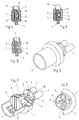
- the igniter according to the invention shown in FIGS. 1 to 8 has a MID carrier 1 on which electronic components are arranged, some of which are provided with the reference number 2. These include electronic components 2 i.a. Semiconductor devices in the form of integrated circuits. On in this way, a bus electronics can be formed for connecting the Detonator to a data bus system, via which commands to trigger the detonator are transferable.
- the MID carrier 1 comprises at least two plastic components in a two-stage (or multi-stage) Injection molding are sprayed together.
- One of the plastic components is using an electrochemical electroplating process on their surface metallized. These metallized areas can be used for training of conductor tracks are used, which the electronic components 2nd contact and connect accordingly.
- Another plastic component is not about this electrochemical electroplating process can be metallized and forms insulating areas on the surface of the MID carrier which, for example, between those by the galvanic metallizations formed conductor tracks lie.
- Several metallized areas or isolating Areas on the surface of the MID carrier are shown in the figures the reference numerals 5 and 6, respectively.
- pins 4 are integral with the MID carrier trained and consist of the galvanically metallizable plastic component. Each of the pins 4 is thus at least on its surface partially covered by a metallization and with metallized areas 5 the electronic components 2 connected in a corresponding manner.
- the igniter has a powder chamber 8 in which a Ignition resistor 7 is arranged.
- the powder chamber is with an ignitable Powder (not shown in the figures) is filled and is on its front a membrane 9 closed.
- a lower part 10 of the side wall and the The rear wall 11 of the powder chamber is formed by the MID carrier.
- the ignition resistance 7 arranged and over metallized areas 5 with the electronic Components 2 connected in a corresponding manner.
- the closure of the powder chamber on the front can also by a cap or by an applied protective lacquer.
- a pyrotechnic material to be introduced into the powder chamber initially liquid, formed from two components to be mixed together pyrotechnic material are used, which then hardens.
- An additional front closure of the powder chamber can be completely omitted.
- the hardened pyrotechnic material is moisture-resistant.
- curable pyrotechnic materials are known.
- Other pyrotechnic too Materials of different consistency can be used here.
- the igniter according to the invention can also be equipped with a heat-conducting device 3 be equipped.
- a heat conduction device 3 serves to increase the Transport safety of the detonator. Should it be during the transportation of the detonator If there is a fire accident, it could happen that the detonator first is heated at its back. Without such a heat conduction device 3 the carrier of the detonator could become so unstable due to its heating, that when the ignition of the powder finally occurs in the powder chamber 8, Parts of the housing could be thrown away.
- Longitudinal section is a heat conducting device from the area of the rear Provided at the end of the detonator metal pin extending into the powder chamber.
- FIGS. 2 to 5 Large-area metallization of the surface of the MID carrier can be provided.
- Large-area metallization is understood here to mean that the metallized areas 5 of the surface of the MID carrier 1 occupy a substantially larger area than the insulating regions 6 lying between them trained metallized areas 5 lead to a significant increase the thermal conductivity from the rear area of the igniter into the powder chamber 8. To further increase the thermal conductivity, one could be from the back Continuous area of the detonator extending into the powder chamber metallized area may be provided.
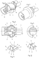
- a conventional squib 12 is provided in the further exemplary embodiment of the invention shown in FIG instead of a powder chamber 8.
- Their Lead wires 13 are with metallized areas on the surface of the MID carrier 1 connected.
- the encapsulation 14 with the further plastic component also surrounds the rear area of the squib 12.
- a heat conduction device 3 in the form of a metal pin extends from the area of rear end of the detonator up to a connecting wire 13 of the squib 12, with which he is connected.
- FIG. 10 corresponds to the embodiment 1, but with the potting compound surrounding the electronic components 16 was omitted.
- This works without damaging the electronic components in the encapsulation through the use of an injection molding process with relatively low temperatures and pressures.
- plastic soft components 15 which here as other plastic components were sprayed onto the MID carrier.
- a plastic bead 17 is formed, which the igniter surrounds along the outer circumference and acts as a seal when the igniter in a cylindrical connecting piece of a drive device for a restraint is introduced in a motor vehicle. Through this seal a Penetration of moisture into the propellant charge of the igniter Drive device prevented.
- the large-area metallization that can be seen in particular from FIGS. 2 to 5 also serves as moisture protection to prevent moisture from penetrating into the To largely prevent powder chamber 8. Such moisture penetration can occur without the use of large-area metallization, that moisture is absorbed by the plastic and diffuses out again becomes. Surface metallization of the plastic is prevented however, the absorption and evaporation of moisture. especially the large-area metallization of the rear wall 11 of the powder chamber 8 and the Large-area metallization of the rear wall 18 of the MID carrier, on which the connection pins are arranged to a high degree prevent diffusion of Moisture in the longitudinal direction of the detonator.
- 11 and 12 are further embodiments of the at the rear end of the MID carrier, connecting pins formed in one piece with the MID carrier shown.
- Fig. 11 is a single pin 4 provided, the plurality of metallized areas 5 with each intermediate isolating areas 6.
- This with the electronic Components 2 are correspondingly connected metallized areas 5 via a pluggable on the pin 4, with appropriate contact springs provided connector can be contacted.
- the connecting pins are 4th formed trough-like, with in the trough-shaped recess of the connecting pins 4th each metallized areas 5 are formed.
- these troughy areas of the Terminal pins 4 can be soldered connecting wires on their opposite free ends are provided with appropriate plugs are.
- the trough-like connecting pins 4 with the soldered connecting wires 13 conveniently encapsulated.
- a housing cover could also be arranged on the MID carrier, which can be potted if necessary.
- MID carriers manufactured by another known technique can be used.
Landscapes
- Engineering & Computer Science (AREA)
- Physics & Mathematics (AREA)
- Fluid Mechanics (AREA)
- Mechanical Engineering (AREA)
- Computer Hardware Design (AREA)
- Microelectronics & Electronic Packaging (AREA)
- General Engineering & Computer Science (AREA)
- Air Bags (AREA)
- Gears, Cams (AREA)
Priority Applications (1)
| Application Number | Priority Date | Filing Date | Title |
|---|---|---|---|
| AT00124126T ATE257103T1 (de) | 1999-11-22 | 2000-11-07 | Zünder |
Applications Claiming Priority (2)
| Application Number | Priority Date | Filing Date | Title |
|---|---|---|---|
| AT197899 | 1999-11-22 | ||
| AT197899 | 1999-11-22 |
Publications (3)
| Publication Number | Publication Date |
|---|---|
| EP1101667A2 true EP1101667A2 (fr) | 2001-05-23 |
| EP1101667A3 EP1101667A3 (fr) | 2001-08-22 |
| EP1101667B1 EP1101667B1 (fr) | 2004-01-02 |
Family
ID=3525186
Family Applications (1)
| Application Number | Title | Priority Date | Filing Date |
|---|---|---|---|
| EP00124126A Expired - Lifetime EP1101667B1 (fr) | 1999-11-22 | 2000-11-07 | Allumeur |
Country Status (4)
| Country | Link |
|---|---|
| US (1) | US6463857B1 (fr) |
| EP (1) | EP1101667B1 (fr) |
| AT (1) | ATE257103T1 (fr) |
| DE (1) | DE50004916D1 (fr) |
Families Citing this family (6)
| Publication number | Priority date | Publication date | Assignee | Title |
|---|---|---|---|---|
| US7690303B2 (en) * | 2004-04-22 | 2010-04-06 | Reynolds Systems, Inc. | Plastic encapsulated energetic material initiation device |
| US8100043B1 (en) | 2008-03-28 | 2012-01-24 | Reynolds Systems, Inc. | Detonator cartridge and methods of use |
| US8276516B1 (en) | 2008-10-30 | 2012-10-02 | Reynolds Systems, Inc. | Apparatus for detonating a triaminotrinitrobenzene charge |
| US8485097B1 (en) | 2010-06-11 | 2013-07-16 | Reynolds Systems, Inc. | Energetic material initiation device |
| EP3735511B1 (fr) * | 2018-01-05 | 2023-03-29 | GeoDynamics, Inc. | Système et procédé de canon de perforation |
| WO2023154306A1 (fr) * | 2022-02-08 | 2023-08-17 | Schlumberger Technology Corporation | Allumeur compact |
Citations (2)
| Publication number | Priority date | Publication date | Assignee | Title |
|---|---|---|---|---|
| AT522U1 (de) | 1994-03-23 | 1995-12-27 | Hirtenberger Ag | Antriebsvorrichtung fuer rueckhaltesysteme in kraftfahrzeugen |
| DE19610799C1 (de) | 1996-03-19 | 1997-09-04 | Siemens Ag | Zündeinrichtung zum Auslösen eines Rückhaltemittels in einem Kraftfahrzeug |
Family Cites Families (14)
| Publication number | Priority date | Publication date | Assignee | Title |
|---|---|---|---|---|
| GB1489269A (en) * | 1974-12-20 | 1977-10-19 | Daimler Benz Ag | Ignition device for a stand-by gas-supply system |
| US5269560A (en) * | 1990-12-18 | 1993-12-14 | Twr Inc. | Initiator assembly for air bag inflator |
| DE4307774A1 (de) * | 1993-03-12 | 1994-09-15 | Dynamit Nobel Ag | Anzündeinrichtung |
| KR100279196B1 (ko) | 1994-09-23 | 2001-02-01 | 에르. 반 오버슈트래텐 | 폴리머 스터드 그리드 어레이 |
| US5882034A (en) * | 1996-05-02 | 1999-03-16 | Motorola, Inc. | Automobile airbag system |
| JP2002513501A (ja) * | 1996-08-12 | 2002-05-08 | トーマス アンド ベッツ インターナショナル インコーポレイテッド | 自動推進の乗物用エアーバッグ・アセンブリーのための無方向導火爆管コネクターアッセンブリー |
| DE19712314A1 (de) * | 1997-03-24 | 1998-10-01 | Thomas & Betts Gmbh | Verbindung für die Zündeinrichtung von Airbag-Systemen in Kraftfahrzeugen |
| US6126197A (en) * | 1997-04-24 | 2000-10-03 | Talley Defense Systems, Inc. | Lightweight discoidal filterless air bag inflator |
| US6276953B1 (en) * | 1997-12-04 | 2001-08-21 | Thoma & Betts International, Inc. | Orientationless squib connector assembly for automotive air bag assemblies |
| US6073963A (en) * | 1998-03-19 | 2000-06-13 | Oea, Inc. | Initiator with injection molded insert member |
| DE19836280C1 (de) * | 1998-08-11 | 2000-05-11 | Telefunken Microelectron | Pyrotechnisches Anzündelement mit integrierter Elektronik, zum Auslösen eines Rückhaltesystems |
| DE19856325A1 (de) * | 1998-12-07 | 2000-06-15 | Bosch Gmbh Robert | Zündvorrichtung für Rückhaltemittel in einem Fahrzeug |
| US6166452A (en) * | 1999-01-20 | 2000-12-26 | Breed Automotive Technology, Inc. | Igniter |
| US6257617B1 (en) * | 1999-03-04 | 2001-07-10 | Trw Inc. | Air bag inflator with pressure regulation |
-
2000
- 2000-11-07 EP EP00124126A patent/EP1101667B1/fr not_active Expired - Lifetime
- 2000-11-07 AT AT00124126T patent/ATE257103T1/de not_active IP Right Cessation
- 2000-11-07 DE DE50004916T patent/DE50004916D1/de not_active Expired - Lifetime
- 2000-11-17 US US09/715,939 patent/US6463857B1/en not_active Expired - Fee Related
Patent Citations (2)
| Publication number | Priority date | Publication date | Assignee | Title |
|---|---|---|---|---|
| AT522U1 (de) | 1994-03-23 | 1995-12-27 | Hirtenberger Ag | Antriebsvorrichtung fuer rueckhaltesysteme in kraftfahrzeugen |
| DE19610799C1 (de) | 1996-03-19 | 1997-09-04 | Siemens Ag | Zündeinrichtung zum Auslösen eines Rückhaltemittels in einem Kraftfahrzeug |
Also Published As
| Publication number | Publication date |
|---|---|
| ATE257103T1 (de) | 2004-01-15 |
| DE50004916D1 (de) | 2004-02-05 |
| EP1101667B1 (fr) | 2004-01-02 |
| US6463857B1 (en) | 2002-10-15 |
| EP1101667A3 (fr) | 2001-08-22 |
Similar Documents
| Publication | Publication Date | Title |
|---|---|---|
| EP0888227B1 (fr) | Dispositif d'allumage permettant de liberer un systeme de retenue dans un vehicule a moteur | |
| DE69737248T2 (de) | Verfahren zum Einkapseln einer integrierten Halbleiterschaltung | |
| EP2012082B1 (fr) | Socle en métal/matériau de fixation pour dispositifs d'amorçage d'airbags ou dispositifs de protection de personnes analogues, en particulier pour véhicules à moteur et dispositif d'amorçage doté d'un tel socle | |
| DE60124374T2 (de) | Zünderkonstruktion mit Aktivierungsschaltung | |
| DE202006020901U1 (de) | Gasgenerator | |
| EP0904613B1 (fr) | Connecteur multibroches a structure conductrice comportant des composants electriques, et procede de fabrication associe | |
| DE102008049404A1 (de) | Elektronische Schaltungsvorrichtung und Verfahren zur Herstellung derselben | |
| WO2008113312A1 (fr) | Ensemble capteur | |
| EP1101667B1 (fr) | Allumeur | |
| EP1170110A1 (fr) | Procédé pour fabriquer une structure conductrice surmoulée en matière plastique d'une unité de circuit électrique ainsi qu'une unité de circuit électrique comprenant une structure conductrice surmoulée en matière plastique | |
| DE60210108T2 (de) | Pyrotechnischer zünder mit bord-steuerschaltungsanordnung | |
| EP0913882A2 (fr) | Méthode pour isoler un dispositif électrique | |
| EP1101668B1 (fr) | Allumeur | |
| DE19940346B4 (de) | Piezoaktor mit einer Anschlußvorrichtung | |
| WO1998054536A1 (fr) | Detonateur pour un generateur de gaz pyrotechnique, et generateur de gaz pyrotechnique | |
| DE102008049650A1 (de) | Gasgenerator, insbesondere für ein Fahrzeuginsassen-Rückhaltesystem, sowie Verfahren zur Herstellung eines Gasgenerators | |
| EP0806626A2 (fr) | Allumeur électrique pour un générateur de gaz pyrotechnique | |
| EP1614989B1 (fr) | Détonateur pour un générateur pyrotechnique à gaz et méthode de fabrication de ce détonateur | |
| EP3640655A1 (fr) | Détecteur de batterie et procédé de fabrication d'un détecteur de batterie | |
| DE10024664A1 (de) | Verfahren zum Herstellen eines Zündmoduls zum Auslösen einer Treibladung, insbesondere einer in einem Insassenschutzmittel enthaltenen Treibladung, sowie Zündmodul | |
| EP0789507B1 (fr) | Dispositif électronique de contrôle encapsulé et procédé pour sa fabrication | |
| DE10125354A1 (de) | Zündvorrichtung für eine Insassenschutzeinrichtung eines Kraftfahrzeuges | |
| EP3465833A2 (fr) | Capteur, procédé et ensemble capteur | |
| AT500478B1 (de) | Zünder für einen pyrotechnischen gasgenerator sowie verfahren zu seiner herstellung | |
| DE102006052705A1 (de) | Zünderbaugruppe |
Legal Events
| Date | Code | Title | Description |
|---|---|---|---|
| PUAI | Public reference made under article 153(3) epc to a published international application that has entered the european phase |
Free format text: ORIGINAL CODE: 0009012 |
|
| AK | Designated contracting states |
Kind code of ref document: A2 Designated state(s): AT BE CH CY DE DK ES FI FR GB GR IE IT LI LU MC NL PT SE TR |
|
| AX | Request for extension of the european patent |
Free format text: AL;LT;LV;MK;RO;SI |
|
| PUAL | Search report despatched |
Free format text: ORIGINAL CODE: 0009013 |
|
| AK | Designated contracting states |
Kind code of ref document: A3 Designated state(s): AT BE CH CY DE DK ES FI FR GB GR IE IT LI LU MC NL PT SE TR |
|
| AX | Request for extension of the european patent |
Free format text: AL;LT;LV;MK;RO;SI |
|
| RIC1 | Information provided on ipc code assigned before grant |
Free format text: 7B 60R 22/46 A, 7B 60R 21/26 B, 7B 60R 21/01 B |
|
| 17P | Request for examination filed |
Effective date: 20011213 |
|
| AKX | Designation fees paid |
Free format text: AT BE CH CY DE DK ES FI FR GB GR IE IT LI LU MC NL PT SE TR |
|
| 17Q | First examination report despatched |
Effective date: 20021211 |
|
| GRAH | Despatch of communication of intention to grant a patent |
Free format text: ORIGINAL CODE: EPIDOS IGRA |
|
| GRAS | Grant fee paid |
Free format text: ORIGINAL CODE: EPIDOSNIGR3 |
|
| GRAA | (expected) grant |
Free format text: ORIGINAL CODE: 0009210 |
|
| AK | Designated contracting states |
Kind code of ref document: B1 Designated state(s): AT BE CH CY DE DK ES FI FR GB GR IE IT LI LU MC NL PT SE TR |
|
| PG25 | Lapsed in a contracting state [announced via postgrant information from national office to epo] |
Ref country code: FI Free format text: LAPSE BECAUSE OF FAILURE TO SUBMIT A TRANSLATION OF THE DESCRIPTION OR TO PAY THE FEE WITHIN THE PRESCRIBED TIME-LIMIT Effective date: 20040102 Ref country code: TR Free format text: LAPSE BECAUSE OF FAILURE TO SUBMIT A TRANSLATION OF THE DESCRIPTION OR TO PAY THE FEE WITHIN THE PRESCRIBED TIME-LIMIT Effective date: 20040102 Ref country code: IE Free format text: LAPSE BECAUSE OF FAILURE TO SUBMIT A TRANSLATION OF THE DESCRIPTION OR TO PAY THE FEE WITHIN THE PRESCRIBED TIME-LIMIT Effective date: 20040102 Ref country code: CY Free format text: LAPSE BECAUSE OF FAILURE TO SUBMIT A TRANSLATION OF THE DESCRIPTION OR TO PAY THE FEE WITHIN THE PRESCRIBED TIME-LIMIT Effective date: 20040102 Ref country code: NL Free format text: LAPSE BECAUSE OF FAILURE TO SUBMIT A TRANSLATION OF THE DESCRIPTION OR TO PAY THE FEE WITHIN THE PRESCRIBED TIME-LIMIT Effective date: 20040102 |
|
| REG | Reference to a national code |
Ref country code: GB Ref legal event code: FG4D Free format text: NOT ENGLISH |
|
| REG | Reference to a national code |
Ref country code: CH Ref legal event code: EP |
|
| REG | Reference to a national code |
Ref country code: IE Ref legal event code: FG4D Free format text: GERMAN |
|
| REF | Corresponds to: |
Ref document number: 50004916 Country of ref document: DE Date of ref document: 20040205 Kind code of ref document: P |
|
| PG25 | Lapsed in a contracting state [announced via postgrant information from national office to epo] |
Ref country code: GR Free format text: LAPSE BECAUSE OF FAILURE TO SUBMIT A TRANSLATION OF THE DESCRIPTION OR TO PAY THE FEE WITHIN THE PRESCRIBED TIME-LIMIT Effective date: 20040402 Ref country code: SE Free format text: LAPSE BECAUSE OF FAILURE TO SUBMIT A TRANSLATION OF THE DESCRIPTION OR TO PAY THE FEE WITHIN THE PRESCRIBED TIME-LIMIT Effective date: 20040402 Ref country code: DK Free format text: LAPSE BECAUSE OF FAILURE TO SUBMIT A TRANSLATION OF THE DESCRIPTION OR TO PAY THE FEE WITHIN THE PRESCRIBED TIME-LIMIT Effective date: 20040402 |
|
| PG25 | Lapsed in a contracting state [announced via postgrant information from national office to epo] |
Ref country code: ES Free format text: LAPSE BECAUSE OF FAILURE TO SUBMIT A TRANSLATION OF THE DESCRIPTION OR TO PAY THE FEE WITHIN THE PRESCRIBED TIME-LIMIT Effective date: 20040413 |
|
| NLV1 | Nl: lapsed or annulled due to failure to fulfill the requirements of art. 29p and 29m of the patents act | ||
| GBT | Gb: translation of ep patent filed (gb section 77(6)(a)/1977) |
Effective date: 20040512 |
|
| RAP2 | Party data changed (patent owner data changed or rights of a patent transferred) |
Owner name: HIRSCHMANN AUTOMOTIVE GMBH |
|
| REG | Reference to a national code |
Ref country code: IE Ref legal event code: FD4D |
|
| ET | Fr: translation filed | ||
| PLBE | No opposition filed within time limit |
Free format text: ORIGINAL CODE: 0009261 |
|
| STAA | Information on the status of an ep patent application or granted ep patent |
Free format text: STATUS: NO OPPOSITION FILED WITHIN TIME LIMIT |
|
| PG25 | Lapsed in a contracting state [announced via postgrant information from national office to epo] |
Ref country code: AT Free format text: LAPSE BECAUSE OF NON-PAYMENT OF DUE FEES Effective date: 20041107 Ref country code: LU Free format text: LAPSE BECAUSE OF NON-PAYMENT OF DUE FEES Effective date: 20041107 |
|
| PG25 | Lapsed in a contracting state [announced via postgrant information from national office to epo] |
Ref country code: CH Free format text: LAPSE BECAUSE OF NON-PAYMENT OF DUE FEES Effective date: 20041130 Ref country code: MC Free format text: LAPSE BECAUSE OF NON-PAYMENT OF DUE FEES Effective date: 20041130 Ref country code: BE Free format text: LAPSE BECAUSE OF NON-PAYMENT OF DUE FEES Effective date: 20041130 Ref country code: LI Free format text: LAPSE BECAUSE OF NON-PAYMENT OF DUE FEES Effective date: 20041130 |
|
| 26N | No opposition filed |
Effective date: 20041005 |
|
| BERE | Be: lapsed |
Owner name: *HIRSCHMANN AUSTRIA G.M.B.H. Effective date: 20041130 |
|
| REG | Reference to a national code |
Ref country code: CH Ref legal event code: PL |
|
| PG25 | Lapsed in a contracting state [announced via postgrant information from national office to epo] |
Ref country code: IT Free format text: LAPSE BECAUSE OF NON-PAYMENT OF DUE FEES Effective date: 20051107 |
|
| BERE | Be: lapsed |
Owner name: *HIRSCHMANN AUSTRIA G.M.B.H. Effective date: 20041130 |
|
| PG25 | Lapsed in a contracting state [announced via postgrant information from national office to epo] |
Ref country code: PT Free format text: LAPSE BECAUSE OF NON-PAYMENT OF DUE FEES Effective date: 20040602 |
|
| PGFP | Annual fee paid to national office [announced via postgrant information from national office to epo] |
Ref country code: GB Payment date: 20071120 Year of fee payment: 8 |
|
| GBPC | Gb: european patent ceased through non-payment of renewal fee |
Effective date: 20081107 |
|
| REG | Reference to a national code |
Ref country code: FR Ref legal event code: TP Ref country code: FR Ref legal event code: CD |
|
| PG25 | Lapsed in a contracting state [announced via postgrant information from national office to epo] |
Ref country code: GB Free format text: LAPSE BECAUSE OF NON-PAYMENT OF DUE FEES Effective date: 20081107 |
|
| PGFP | Annual fee paid to national office [announced via postgrant information from national office to epo] |
Ref country code: DE Payment date: 20091120 Year of fee payment: 10 |
|
| PGFP | Annual fee paid to national office [announced via postgrant information from national office to epo] |
Ref country code: FR Payment date: 20091019 Year of fee payment: 10 |
|
| REG | Reference to a national code |
Ref country code: FR Ref legal event code: ST Effective date: 20110801 |
|
| REG | Reference to a national code |
Ref country code: DE Ref legal event code: R119 Ref document number: 50004916 Country of ref document: DE Effective date: 20110601 Ref country code: DE Ref legal event code: R119 Ref document number: 50004916 Country of ref document: DE Effective date: 20110531 |
|
| PG25 | Lapsed in a contracting state [announced via postgrant information from national office to epo] |
Ref country code: FR Free format text: LAPSE BECAUSE OF NON-PAYMENT OF DUE FEES Effective date: 20101130 |
|
| PG25 | Lapsed in a contracting state [announced via postgrant information from national office to epo] |
Ref country code: DE Free format text: LAPSE BECAUSE OF NON-PAYMENT OF DUE FEES Effective date: 20110531 |