EP1101517B1 - Bubble-removing apparatus - Google Patents
Bubble-removing apparatus Download PDFInfo
- Publication number
- EP1101517B1 EP1101517B1 EP00124305A EP00124305A EP1101517B1 EP 1101517 B1 EP1101517 B1 EP 1101517B1 EP 00124305 A EP00124305 A EP 00124305A EP 00124305 A EP00124305 A EP 00124305A EP 1101517 B1 EP1101517 B1 EP 1101517B1
- Authority
- EP
- European Patent Office
- Prior art keywords
- float
- bubble
- space
- cylinder
- bubbles
- Prior art date
- Legal status (The legal status is an assumption and is not a legal conclusion. Google has not performed a legal analysis and makes no representation as to the accuracy of the status listed.)
- Expired - Lifetime
Links
- 239000012530 fluid Substances 0.000 claims description 16
- 239000000758 substrate Substances 0.000 claims description 4
- 239000007788 liquid Substances 0.000 description 34
- 238000004140 cleaning Methods 0.000 description 8
- 230000010349 pulsation Effects 0.000 description 8
- 239000000126 substance Substances 0.000 description 8
- 230000008859 change Effects 0.000 description 6
- 230000000694 effects Effects 0.000 description 3
- 239000000463 material Substances 0.000 description 3
- 238000005259 measurement Methods 0.000 description 3
- 239000000203 mixture Substances 0.000 description 3
- 239000006185 dispersion Substances 0.000 description 2
- 238000000034 method Methods 0.000 description 2
- 238000012856 packing Methods 0.000 description 2
- 239000004065 semiconductor Substances 0.000 description 2
- YCKRFDGAMUMZLT-UHFFFAOYSA-N Fluorine atom Chemical compound [F] YCKRFDGAMUMZLT-UHFFFAOYSA-N 0.000 description 1
- 239000004809 Teflon Substances 0.000 description 1
- 229920006362 Teflon® Polymers 0.000 description 1
- 239000002253 acid Substances 0.000 description 1
- 230000002378 acidificating effect Effects 0.000 description 1
- 230000009471 action Effects 0.000 description 1
- 239000003513 alkali Substances 0.000 description 1
- 239000002585 base Substances 0.000 description 1
- 230000008901 benefit Effects 0.000 description 1
- 238000007796 conventional method Methods 0.000 description 1
- 238000002474 experimental method Methods 0.000 description 1
- 229910052731 fluorine Inorganic materials 0.000 description 1
- 239000011737 fluorine Substances 0.000 description 1
- 239000002828 fuel tank Substances 0.000 description 1
- 230000005484 gravity Effects 0.000 description 1
- 230000010354 integration Effects 0.000 description 1
- 239000000314 lubricant Substances 0.000 description 1
- 238000004519 manufacturing process Methods 0.000 description 1
- 230000007246 mechanism Effects 0.000 description 1
- 239000007769 metal material Substances 0.000 description 1
- 238000012986 modification Methods 0.000 description 1
- 230000004048 modification Effects 0.000 description 1
- 239000003921 oil Substances 0.000 description 1
- 229920005989 resin Polymers 0.000 description 1
- 239000011347 resin Substances 0.000 description 1
- 230000004044 response Effects 0.000 description 1
- 229920003002 synthetic resin Polymers 0.000 description 1
- 239000000057 synthetic resin Substances 0.000 description 1
- 238000012546 transfer Methods 0.000 description 1
- XLYOFNOQVPJJNP-UHFFFAOYSA-N water Substances O XLYOFNOQVPJJNP-UHFFFAOYSA-N 0.000 description 1
Images


Classifications
-
- B—PERFORMING OPERATIONS; TRANSPORTING
- B01—PHYSICAL OR CHEMICAL PROCESSES OR APPARATUS IN GENERAL
- B01D—SEPARATION
- B01D19/00—Degasification of liquids
- B01D19/0063—Regulation, control including valves and floats
-
- B—PERFORMING OPERATIONS; TRANSPORTING
- B01—PHYSICAL OR CHEMICAL PROCESSES OR APPARATUS IN GENERAL
- B01D—SEPARATION
- B01D19/00—Degasification of liquids
- B01D19/0042—Degasification of liquids modifying the liquid flow
- B01D19/0052—Degasification of liquids modifying the liquid flow in rotating vessels, vessels containing movable parts or in which centrifugal movement is caused
- B01D19/0057—Degasification of liquids modifying the liquid flow in rotating vessels, vessels containing movable parts or in which centrifugal movement is caused the centrifugal movement being caused by a vortex, e.g. using a cyclone, or by a tangential inlet
Definitions
- the present invention relates to a bubble-removing apparatus for removing bubbles entrained in a liquid when various fluids such as water, oil or chemicals are used.
- a cleaning solution composed of acidic chemicals or alkaline chemicals at a constant mixing ratio is circulated in a cleaning bath in a predetermined amount to conduct automatic cleaning of semiconductor substrates.
- a cleaning solution composed of acidic chemicals or alkaline chemicals at a constant mixing ratio
- a bubble-removing apparatus wherein a liquid is fluidized by turning it in a vessel and the bubbles are collected at the central portion for removal in order to use the apparatue even when the flow amount is small.
- this apparatus is disclosed in JP-A-11-19406. According to the description of this publication, the apparatus can be used even in a case of a liquid in a small flow amount, and is constructed to separate bubbles and collect the bubbles to the central axis of a vessel by a rotating flow and discharge the bubbles through a discharge outlet provided at the central axis of the vessel.
- an automatic on-off valve is disposed at the discharge outlet of this apparatus.
- This valve has a mechanism whererein a spherical discharge valve floatis raised by the buoyancy of the liquid to shut a discharge outlet, and when bubbles are collected, the discharge valve float is released from the outlet by its own weight and a spring to discharge the bubbles through the outlet.
- a bubble-removing apparatus wherein an air bent having a ball valve, using simply a ball and not using a spring, is disposed at the discharge outlet.
- the ball is unstable, and when the flow amount increases, the ball will float in the air bent and the liquid will flow out together with the bubbles. Further, when the ball is raised and shuts the discharge outlet of the air bent, the liquid containing bubbles will flow out from the outflow port of the bubble-removing apparatus, resulting in failure of removal of bubbules.
- a pump is used in order to permit the liquid to flow into a cleaning solution or the like through the above bubble removing apparauts.
- the pump does not necessarily create a constant pressure at all times.
- the pressure can not be kept constant and pulsation is caused, whereby the flow amount becomes unstable due to the transfer of such pulsation, and problems may sometimes be caused when the above liquid is used in the in the subsequent step.
- the bubble-removing apparatus of the present invention comprises a main body; a cylindrical inflow space;an inverted conical space which communicates with the inflow space; a little cylindrical outflow space which communicates with the inverted conical space: an inflow port which opens to the inflow space and an outflow port which opens to the outflow space, both being provided in a tangential direction of the inflow space and the outflow space, respectively, so that a fluid can rotate and flow in the spaces; an axial shaft at the center; and a discharge outlet of bubbles at a central upper portion of the in flow space, wherein a valve chamber is formed between the discharge outlet and the inflow space; a cylinder having a through hole which opens to the inflow space; a cylinder having a through hole which opens to the inflow space in the valve chamber; a cap-like having a cylindrical wall which surrounds the cylindrical and has an upper plate which closes the upper end portion of the cylinder wall, is formed; and the float is loosely capped with an upper portion of the cylinder and at
- Fig. 1 and Fig. 2 are a sectional view and a plane view showing an example of the present invention.
- a cylindrical inflow space 2 in a cylindrical main body 1, a cylindrical inflow space 2; an inverted conical space 3 which communicates with the lower portion of the inflow space 2 and slants toward the center; and a little cylindrical outflow space 4 which communicates with the lower portion of the inverted conical space 3 and is smaller than the cylinder of the inflow space 2, are formed, and an inflow port 5 and an outflow port 6 are provided at the inflow space 2 and the outflow space 4, respetively.
- the inflow port 5 and outflow port 6 open to the spaces 2 and 4, respectively, in a tangential direction of these spaces so that a fluid can rotate and flow in the spaces 2, 3 and 4.
- the inflow port 5 may be provided in a plural number. Particularly, when the viscosity of the fluid is high, by permitting the fluid to flow into the space through the plural inflow ports, the flow amount and rotation can be increased, whereby the center of flow can be made clear and made clear and bubbles can be easily collected.
- an axial shaft 7 is provided. Bubbles which gather around the center of flow (not shown) of the fluid rotating and flowing in the spaces, are caught around the axial shaft 7, and bubbles are entrained or incorporated one another to form large bubble's core (not shown ) and the bubbles are raised along the axial shaft. At that time, the bubble s core is like a narrow column, so the bubble's core is not swung toward the inner wall side of the space by the rotating flow of the fluid and become more stable. If the axial shaft 7 becomes thick, the outflow space is narrowed, the internal pressure increases and the rise of the bubbles can be acceelerated. If the inner diameter of the outflow port 6 is made smaller than the inflow port 5, the same effect can be obtained.
- a discharge outlet 8 of bubbles is formed, and between the discharge port 8 and the inflow space 2, a valve chamber 9 is formed.
- the discharge port 8 and the valve chamber 9 are disposed at a cover 11 which is fixed to the main body 1 by a screw 10..., and between the main body 1 and the cover 11, an appropriate packing material (not shown) may be provided.
- the cover and the main body may have screws provided thereon and both may be connected by the screws. Further, after the cover is attached to the main body, the joint portion may be welded for integration.
- a cylinder 13 having a through hole 12 which opens to the inflow space 2 is provided.
- the cylinder 13 is integrally formed with a substrate 14 which is fitted with the upper portion of the inflow space 2 of the main body 1 and its periphery is clamped by the cover 11.
- the cylinder 13 may be formed on the cover 11 and a fixing plate 15 having a discharge outlet 8 may be screwed thereon (Fig. 5).
- appropriate structures may be applied, for example, a fixing plate 16 having the cylinder 13 protruded therefrom, may be screwed from the lowerside into the cover 11 (Fig. 6).
- a float 17 which is loosely engaged with the cylinder 13 and at the same time, fitted with the valve chamber in an upwardly and downwardly movable state while permitting a narrow gap.
- the float 17 is formed in a cap-like shape having a cylindrical wall 18 which surrounds the cylinder 13 and has an inner diameter which is a little larger than an outer diameter of the cylinder 13. and un upper plate 19 which closes the upper end portion of the cylindrical wall 18. In a state where the plate 19 is seated on the upper portion of the cylinder 13 and the plate 19 shuts the through hole 12, the lower end of the cyindrical wall 18 does not abut the base end of the cylinder 13.
- an outward ring 22 is engaged while permitting narrow gaps 20 and 21, respectively, so that it can move upwardly and downwardly.
- the outward ring 22 may be omitted.
- a packing 23 may be provided at an appropriate portion such as the inner face or the like of the plate 19.
- the gaps are formed to be extremely narrow so that, preferably, only bubbles can be efficiently passed without passing the liquid.
- the narrow gap in the case of a water-type liquid, the narrow gapis within a range of from about 0.05 mm to 0.3 mm, preferably from about 0.1 mm to 0.2 mm, and in the case of an oil-type liquid, the narrow gap is within a range of from about 0.2 mm to 1 mm, preferably from about 0.5 mm to 0.8 mm.
- the float 17 When the internal pressure in the main body increases, the float 17 is raised by the pressure, and the plate 19 comes away from the upper surface of the cylinder and lets the through hole 12 open and the bubbles pass. However,when the pressure is so large that the liquid spouts through the through hole 12, the float 17 is immediately raised upwardly so that the liquid will not flow out from the discharge port 8 of bubbles and placed directly under the discharge port 8 so that the discharge port 8 will be shut by the upper surface of the plate. The float 17 can move until the plate 19 abuts to the inner upper portion of the valve chamber 9.
- This movement is restricted to a level such that under usual conditions, only bubbles can be securely discharged and the discharge outlet 8 will not be shut, for example, to from about 1 to 5 mm, preferably from about 1 to 3 mm.
- the length of the cylindrical wall 18 of the float 17 is restricted to a level such that even if the float rises, it does not come away from the the cylinder 13.
- the main body 1.cover 11, cylinder 13, float 17, outward ring 22 and the like are made from an appropriate synthetic resin material such as Teflon (fluorine resin), but may be made from an anti-corrosive metal material such as a stainless material.
- the plate 19 of the float 17 is formed to have flat upper and lower surfaces. However, the plate may have a protrusion (not shown)having an appropriate shape so that it fits with and shuts the through hole 12 or discharge outlet 8. Further, if the case requires, an elastic member such as an anticorrosive spring may be provided between the float and discharge outlet, but there is substantially no such necessity.
- FIG. 3(A) shows a state wherein even when the bubbles separated from the liquid rotating and flowing in the main body gather to the upper portion of the inflow space 2, the internal pressure has not been increased to a level such that it presses the float 17 upwardly. In the meantime, the internal pressure is gradually increased, and with the increassof the internal pressure, even light and small bubbles are collected to the float portion.
- 3(A) is created also when a pump for supplying the liquid to the infow port 5 is stopped, and in this state, the float is seated on the cylinder and shuts the through hole 12; i.e., the float functions as a check valve.
- the float 17 When the bubbles are separated from the liquid and concentrated at the upper portion so as to sufficiently increase the internal pressure, the float 17 is pressed upwardly (Fig. 3(B)). By this his movement, the bubbles which passed through the through hole 12 pass from the lower surface of the plate 19 of the float 17 through the narrow gap 24 between the inner surface of the float and the cylinder, travel along the lower edge of the float 17. pass the narrow gap 20 at the outer periphery of the float 17, and then are removed from the discharge outlet 8. Since the internal pressure is thereby lowered, the float 17 moves down to the position as shwn in Fig.3(A) but when the internal pressure is raised again, the float 17 moves upwardly as shown in Fig. 3(B) and discharge the bubbles.
- the float 17 moves upwardly and downwardly, and conducts piston travel against the cylinder 13.
- the bubbles show the function of a lubricant between the cylinder and the float, and the float can move smoothly. Since the narrow gaps are extremely narrow as mentioned above, the liquid entrained in the mixture of the bubbles and liquid can hardly pass therethrough, and only bubbles can be discharged from the dischargle outlet.
- the effect for removal of bubbles can be confirmed by measuring the count of an ultrasonic flow meter which is susceptible to the influence of bubbles.
- a level sensor and an ultrasonic flow meter were used in combination, and the supply amount was adjusted to 5,500 cc per minute by the level sensor, and the count of the ultrasonic flow meter was measured when the supply was terminated in response to the adjustment.
- the average count of the ultrasonic flow meter (amount calculated as the flow amount; cc) was 5,539 cc when the bubble-removing apparatus of the present invention was used for the flow meter, whereas it was 5,638 cc when a conventional bubble-removing method was used. Further, the dispersion of the count was ⁇ 2.1 % when the bubble-removing apparatus of the present invention was used, whereas it was ⁇ 6.9 % when a conventional method was used.
- the average count shows the difference of 0.7 % against the adjusted value (5,500 cc), and is 1/4 of the case where the apparatus of the present invention was not used,i.e. the accuracy was improved by the present invention. Further, the dispersion of the count was about 1/3 of the case where the apparatus of the present invention was not used, and it was found that stable counts were recorded. Accordingly, the bubble-removing apparatus of the present invention securely discharged the bubbles, and it was confirmed that this apparatus can be sufficiently used for the ultrasonic flow meter which is susceptible to the influence of bubbles as mentioned above.
- Fig. 7 is a graph showing the change of the flow rate when a liquid was supplied at a flow rate of 2.5 liters per minute using a diagphram pump. As compared with the case where the liquid was passed through the bubble-removing apparatus of the present invention (A), a large pulsation is confirmed in the case where the liquid was not passed through it (B).
- the internal pressure can be controlled, and the pulsation of the fluid flowing out from the discharge outlet 6 can be buffered, and in addition, by the upward and downward movement of the outward ring, the pulsation can further be removed.
- the apparatus of the present invention may appropriately be constructed, for example, a filter is provided in the main body, an on-off valve is provided at the outside of the discharge outlet of bubbles for control, or or plural apparatuses are continuously connected to remove the bubbles stepwise.
- the apparatus of the present invention is constructed as described above, i.e. a bubble-removing apparatus, which comprises a main body; a cylindrical inflow space; an inverted conical space which communicates with the inflow space; a little cylindrical outflow space which communicates with the inverted conical space; an inflow port which opens to the inflow space and an outflow port which opens to the outflow space, both being provided in a tangential direction of the inflow space and the outflow space, respectively, so that a fluid can rotate and flow in the spaces; an axial shaft at the center; and a dischrge outlet of bubbles at a central upper portion of the inflow space, wherein a valve chamber is formed between the discharge outlet and the inflow space; a cylinder having a through hole which opens to the inflow space in the valve chamber; a cap-like float having a cylindrical wall which surrounds the cylinder and has an upper plate which closes the upper end portion of the cylindrical wall, is formed; and the float is loosely capped with an upper portion of
- the bubbles gathered around the central upper portion of the main body can be efficiently removed from the discharge outlet, by the piston travel of the float loosely engaged with the cylinder.
- the apparatus of the present invention can be applied to the case of a small flow amount. A mixture of bubbles and a liquid is hardly permitted to flow out. Even if the flow amount flowing into the main body fluctuates, it is possible to cope with the trouble within a wide range and securely remove the bubbles. Further, the internal pressure in the main body can be controlled by the piston travel of the float and pulsation can be buffered.
Landscapes
- Chemical & Material Sciences (AREA)
- Chemical Kinetics & Catalysis (AREA)
- Degasification And Air Bubble Elimination (AREA)
- External Artificial Organs (AREA)
Description
- The present invention relates to a bubble-removing apparatus for removing bubbles entrained in a liquid when various fluids such as water, oil or chemicals are used.
- Various fluids are used for various purposes. In such use, inconvinience is often caused when bubbles are entrained in the fluids. For example, in a cleaning step of semiconductor production, a cleaning solution composed of acidic chemicals or alkaline chemicals at a constant mixing ratio, is circulated in a cleaning bath in a predetermined amount to conduct automatic cleaning of semiconductor substrates. In this case, in order to realize the cleaning effects stably with good reproducibility, it is important to maintain a constant mixing ratio of chemicals, and for this purpose, stable supply of chemicals in a predetermined amount is demanded.
- Various methods have been used for measurement of supplied amount in an automatic supply of the cleaning solution. Recently, an ultrasonic flow meter which is advantageous for miniaturization of apparatus and fluctuation of pressure has been widely used. This flow meter has an advantage that the supplied amount can readily be changed and the mixing ratio of chemicals can thereby be simply adjusted automatically. However, from the aspect of its structure, the ultrasonic flow meter is suspectible to the influence of its bubbles in the cleaning solution, and accurate measurement can not be made without eliminating the bubbles. These bubbles are formed by causes, for example, the change of canisters of chemicals or pump operation by e.g. a diaphragm pump.For this reason, various types of bubble-removing apparatuses have been proposed and employed. However, in many cases, when bubbles are discharged, solution is entrained in the bubbles and are discharged together in a large amount, or a pump, a tank and a removing device are integrateed and thereby the entire apparatus becomes large in size, and an operation of a small flow amount can not be conducted.
- A bubble-removing apparatus has been known wherein a liquid is fluidized by turning it in a vessel and the bubbles are collected at the central portion for removal in order to use the apparatue even when the flow amount is small. For example, this apparatus is disclosed in JP-A-11-19406. According to the description of this publication, the apparatus can be used even in a case of a liquid in a small flow amount, and is constructed to separate bubbles and collect the bubbles to the central axis of a vessel by a rotating flow and discharge the bubbles through a discharge outlet provided at the central axis of the vessel. At the discharge outlet of this apparatus, an automatic on-off valve is disposed. This valve has a mechanism whererein a spherical discharge valve floatis raised by the buoyancy of the liquid to shut a discharge outlet, and when bubbles are collected, the discharge valve float is released from the outlet by its own weight and a spring to discharge the bubbles through the outlet.
- However, in the case of the on-off valve of the above mentioned apparatus, since it is necessary to use the spring to securely open the discharge outlet, when the liquid is chemicals of e.g. acid or alkali, it is dificult to maintain a stable performance for a long period of time. Futher, operation of the valve varies depending upon the balance of e.g. the discharge valve float's own weight, the spring force of the spring and the buoyancy of the discharge valve float. Accordingly, when the internal pressure inside the vessel largely changes by the flow amount of the liquid which flows into the vessel, the operation of the valve can not follow the change. For this reason, with one type of this aparatus alone, it has been impossible to treat a liquid which is to be used for the case where the flow amount largely changes.
- A bubble-removing apparatus has been known wherein an air bent having a ball valve, using simply a ball and not using a spring, is disposed at the discharge outlet. However, in this structure, the ball is unstable, and when the flow amount increases, the ball will float in the air bent and the liquid will flow out together with the bubbles. Further, when the ball is raised and shuts the discharge outlet of the air bent, the liquid containing bubbles will flow out from the outflow port of the bubble-removing apparatus, resulting in failure of removal of bubbules. In addition, in the case of a ball, since its outward appearance is spherical, when the ball moves only a little, the liquid flows into the air bent and the air bent is filled with the liquid, whereby the ball is made further unstable and it becomes difficult to keep balance with the flow amount.
- Further, a pump is used in order to permit the liquid to flow into a cleaning solution or the like through the above bubble removing apparauts. However, in usual, the pump does not necessarily create a constant pressure at all times. Particularly, with diaphragm pumps, air-actuated pump and the like, the pressure can not be kept constant and pulsation is caused, whereby the flow amount becomes unstable due to the transfer of such pulsation, and problems may sometimes be caused when the above liquid is used in the in the subsequent step.
- The document PATENT ABSTRACTS OF JAPAN vol. 012, no. 332 (M-738) describes a gas separator for a fuel tank comprising a float valve.
- It is an object of the present invention to provide a bubble-removing apparatus which can be used also for removal of bubbles from a liquid of a small flow amount, and by which only bubbles can be securely removed without permitting the liquid to flow out from the discharge outlet of the bubbles and it is possible to cope with a large change of a flow amount only by one type of apparatus alone.
- It is another object of the present invention to provide a bubble-removing apparatus, by which pulsation can be buffered and at the same time bubbles can be removed, even when a pump which tends to create the pulsation in flow amount like the above mentioned diagphram pump or the like, is used.
- The bubble-removing apparatus of the present invention comprises a main body; a cylindrical inflow space;an inverted conical space which communicates with the inflow space; a little cylindrical outflow space which communicates with the inverted conical space: an inflow port which opens to the inflow space and an outflow port which opens to the outflow space, both being provided in a tangential direction of the inflow space and the outflow space, respectively, so that a fluid can rotate and flow in the spaces; an axial shaft at the center; and a discharge outlet of bubbles at a central upper portion of the in flow space,
wherein a valve chamber is formed between the discharge outlet and the inflow space; a cylinder having a through hole which opens to the inflow space; a cylinder having a through hole which opens to the inflow space in the valve chamber; a cap-like having a cylindrical wall which surrounds the cylindrical and has an upper plate which closes the upper end portion of the cylinder wall, is formed; and the float is loosely capped with an upper portion of the cylinder and at the same time, disposed in the valve chamber in an upwardly an downwardly movable state while permitting a narrow gap. The above objects are thereby accomplished. -
- Fig. 1 is a sectional view showing an example of the present invention.
- Fig. 2 is a plane view.
- Fig. 3(A) to 3(C) are views illustrating the operation of a float and showing an enlarged view of a narrow gap, for the sake of explanation. Fig. 3(A) illustrates the case where the float moves down. Fig. 3(B) illustrates the case where the float is raised. Fig. 3(C) illustrates the case where the float is raised to the uppermost part.
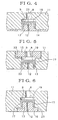
- Fig. 4 is a partial sectional view showing another example of a valve chamber.
- Fig. 5 is a partial sectional view showing a still another example of a valve chamber.
- Fig. 6 is a partial sectional view showing a further example of a valve chamber.
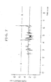
- Fig. 7 is a graph showing the change of the flow amount between the case where the bubble-removing apparatus of the present invention is used and the case where it is not used.
- Fig. 1 and Fig. 2 are a sectional view and a plane view showing an example of the present invention. In these figures, in a cylindrical
main body 1, acylindrical inflow space 2; an invertedconical space 3 which communicates with the lower portion of theinflow space 2 and slants toward the center; and a littlecylindrical outflow space 4 which communicates with the lower portion of the invertedconical space 3 and is smaller than the cylinder of theinflow space 2, are formed, and aninflow port 5 and anoutflow port 6 are provided at theinflow space 2 and theoutflow space 4, respetively. Theinflow port 5 andoutflow port 6 open to thespaces spaces inflow port 5 may be provided in a plural number. Particularly, when the viscosity of the fluid is high, by permitting the fluid to flow into the space through the plural inflow ports, the flow amount and rotation can be increased, whereby the center of flow can be made clear and made clear and bubbles can be easily collected. - At the center of the spaces, an
axial shaft 7 is provided. Bubbles which gather around the center of flow (not shown) of the fluid rotating and flowing in the spaces, are caught around theaxial shaft 7, and bubbles are entrained or incorporated one another to form large bubble's core (not shown ) and the bubbles are raised along the axial shaft. At that time, the bubble s core is like a narrow column, so the bubble's core is not swung toward the inner wall side of the space by the rotating flow of the fluid and become more stable. If theaxial shaft 7 becomes thick, the outflow space is narrowed, the internal pressure increases and the rise of the bubbles can be acceelerated. If the inner diameter of theoutflow port 6 is made smaller than theinflow port 5, the same effect can be obtained. - At the central upper portion of the
inflow space 2, adischarge outlet 8 of bubbles is formed, and between thedischarge port 8 and theinflow space 2, avalve chamber 9 is formed. In the figures, thedischarge port 8 and thevalve chamber 9 are disposed at acover 11 which is fixed to themain body 1 by ascrew 10..., and between themain body 1 and thecover 11, an appropriate packing material (not shown) may be provided. The cover and the main body may have screws provided thereon and both may be connected by the screws. Further, after the cover is attached to the main body, the joint portion may be welded for integration. - In the
valve chamber 9,acylinder 13 having a throughhole 12 which opens to theinflow space 2 is provided. In Fig. 1 and Fig. 2. thecylinder 13 is integrally formed with asubstrate 14 which is fitted with the upper portion of theinflow space 2 of themain body 1 and its periphery is clamped by thecover 11. However, thecylinder 13 may be formed on thecover 11 and a fixingplate 15 having adischarge outlet 8 may be screwed thereon (Fig. 5). Further, appropriate structures may be applied, for example, a fixingplate 16 having thecylinder 13 protruded therefrom, may be screwed from the lowerside into the cover 11 (Fig. 6). - To the
cylinder 13 inthe.valve chamber 9, is provided afloat 17 which is loosely engaged with thecylinder 13 and at the same time, fitted with the valve chamber in an upwardly and downwardly movable state while permitting a narrow gap. Thefloat 17 is formed in a cap-like shape having acylindrical wall 18 which surrounds thecylinder 13 and has an inner diameter which is a little larger than an outer diameter of thecylinder 13. and unupper plate 19 which closes the upper end portion of thecylindrical wall 18. In a state where theplate 19 is seated on the upper portion of thecylinder 13 and theplate 19 shuts the throughhole 12, the lower end of thecyindrical wall 18 does not abut the base end of thecylinder 13. In these figures, between the outer face of thefloat 17 and the inner face of thevalve chamber 9, anoutward ring 22 is engaged while permittingnarrow gaps outward ring 22 may be omitted. Further, a packing 23 may be provided at an appropriate portion such as the inner face or the like of theplate 19. - With respect to the
narrow gap 24 between the inner surface of thefloat 17 and the outer surface of thecylinder 13, thenarrow gap 20 between the outer surface of thefloat 17 and the inner face of the valve chamber 9 (in Fig. 1 and the like, the inner surface of the outward ring 22), thenarrow gap 21 on the outer surface of theoutward ring 22 and the like, depending upon the properties such as the viscosity, specific gravity and the like of the liquid from which bubbles will be removed, the gaps are formed to be extremely narrow so that, preferably, only bubbles can be efficiently passed without passing the liquid. For example, in the case of a water-type liquid, the narrow gapis within a range of from about 0.05 mm to 0.3 mm, preferably from about 0.1 mm to 0.2 mm, and in the case of an oil-type liquid, the narrow gap is within a range of from about 0.2 mm to 1 mm, preferably from about 0.5 mm to 0.8 mm. - When the internal pressure in the main body increases, the
float 17 is raised by the pressure, and theplate 19 comes away from the upper surface of the cylinder and lets the throughhole 12 open and the bubbles pass. However,when the pressure is so large that the liquid spouts through the throughhole 12, thefloat 17 is immediately raised upwardly so that the liquid will not flow out from thedischarge port 8 of bubbles and placed directly under thedischarge port 8 so that thedischarge port 8 will be shut by the upper surface of the plate. Thefloat 17 can move until theplate 19 abuts to the inner upper portion of thevalve chamber 9. This movement is restricted to a level such that under usual conditions, only bubbles can be securely discharged and thedischarge outlet 8 will not be shut, for example, to from about 1 to 5 mm, preferably from about 1 to 3 mm. The length of thecylindrical wall 18 of thefloat 17 is restricted to a level such that even if the float rises, it does not come away from the thecylinder 13. - The main body 1.
cover 11,cylinder 13,float 17,outward ring 22 and the like are made from an appropriate synthetic resin material such as Teflon (fluorine resin), but may be made from an anti-corrosive metal material such as a stainless material. Theplate 19 of thefloat 17 is formed to have flat upper and lower surfaces. However, the plate may have a protrusion (not shown)having an appropriate shape so that it fits with and shuts the throughhole 12 ordischarge outlet 8. Further, if the case requires, an elastic member such as an anticorrosive spring may be provided between the float and discharge outlet, but there is substantially no such necessity. - In Fig. 3(A) to 3(C), the movement of the float is illustrated, and for the sake of explanation, the respective narrow gaps are enlarged. Fig. 3(A) shows a state wherein even when the bubbles separated from the liquid rotating and flowing in the main body gather to the upper portion of the
inflow space 2, the internal pressure has not been increased to a level such that it presses thefloat 17 upwardly. In the meantime, the internal pressure is gradually increased, and with the increassof the internal pressure, even light and small bubbles are collected to the float portion. The state of Fig. 3(A) is created also when a pump for supplying the liquid to theinfow port 5 is stopped, and in this state, the float is seated on the cylinder and shuts the throughhole 12; i.e., the float functions as a check valve. - When the bubbles are separated from the liquid and concentrated at the upper portion so as to sufficiently increase the internal pressure, the
float 17 is pressed upwardly (Fig. 3(B)). By this his movement, the bubbles which passed through the throughhole 12 pass from the lower surface of theplate 19 of thefloat 17 through thenarrow gap 24 between the inner surface of the float and the cylinder, travel along the lower edge of thefloat 17. pass thenarrow gap 20 at the outer periphery of thefloat 17, and then are removed from thedischarge outlet 8. Since the internal pressure is thereby lowered, thefloat 17 moves down to the position as shwn in Fig.3(A) but when the internal pressure is raised again, thefloat 17 moves upwardly as shown in Fig. 3(B) and discharge the bubbles. By repeating this operation, thefloat 17 moves upwardly and downwardly, and conducts piston travel against thecylinder 13. At this time, the bubbles show the function of a lubricant between the cylinder and the float, and the float can move smoothly. Since the narrow gaps are extremely narrow as mentioned above, the liquid entrained in the mixture of the bubbles and liquid can hardly pass therethrough, and only bubbles can be discharged from the dischargle outlet. - When the internal pressure becomes extremely high by over increase of flow amount and the liquid passes through the through
hole 12 and reaches the float portion, thefloat 17 is raised by the pressure to the position where it contacts with the inner upper portion of thevalve chamber 9, and shuts the discharge outlet 8 (Fig. 3(C)). Accordingly, it is possible to prevent the liquid from flowing out from thedischarge outlet 8. - According to the results of experiments, it is possible to use a one type of apparatus alone for the removal of bubbles of a liquid which undergoes flow rate change of about 0.5 to 5.0 liters per minute. Further, under the condition wherein bubbles are entrained continuously, the amount of the mixture of the bubbles and liquid to be discharged from the discharge outlet can be reduced to about 0.066 % or less of the entire flow amount.
- The effect for removal of bubbles can be confirmed by measuring the count of an ultrasonic flow meter which is susceptible to the influence of bubbles.
- As a measurement device, a level sensor and an ultrasonic flow meter were used in combination, and the supply amount was adjusted to 5,500 cc per minute by the level sensor, and the count of the ultrasonic flow meter was measured when the supply was terminated in response to the adjustment.
- The average count of the ultrasonic flow meter (amount calculated as the flow amount; cc) was 5,539 cc when the bubble-removing apparatus of the present invention was used for the flow meter, whereas it was 5,638 cc when a conventional bubble-removing method was used. Further, the dispersion of the count was ±2.1 % when the bubble-removing apparatus of the present invention was used, whereas it was ±6.9 % when a conventional method was used.
- From this result, when the bubble-removing apparatus of the present invention was used, the average count shows the difference of 0.7 % against the adjusted value (5,500 cc), and is 1/4 of the case where the apparatus of the present invention was not used,i.e. the accuracy was improved by the present invention. Further, the dispersion of the count was about 1/3 of the case where the apparatus of the present invention was not used, and it was found that stable counts were recorded. Accordingly, the bubble-removing apparatus of the present invention securely discharged the bubbles, and it was confirmed that this apparatus can be sufficiently used for the ultrasonic flow meter which is susceptible to the influence of bubbles as mentioned above.
- Fig. 7 is a graph showing the change of the flow rate when a liquid was supplied at a flow rate of 2.5 liters per minute using a diagphram pump. As compared with the case where the liquid was passed through the bubble-removing apparatus of the present invention (A), a large pulsation is confirmed in the case where the liquid was not passed through it (B).
- As mentioned above, it was confirmed that according to the apparatus of the present invention, by the piston travel of the float and the action of the
substrate 14 like a diaphragm, the internal pressure can be controlled, and the pulsation of the fluid flowing out from thedischarge outlet 6 can be buffered, and in addition, by the upward and downward movement of the outward ring, the pulsation can further be removed. - The apparatus of the present invention may appropriately be constructed, for example, a filter is provided in the main body, an on-off valve is provided at the outside of the discharge outlet of bubbles for control, or or plural apparatuses are continuously connected to remove the bubbles stepwise.
- The apparatus of the present invention is constructed as described above, i.e. a bubble-removing apparatus, which comprises a main body; a cylindrical inflow space; an inverted conical space which communicates with the inflow space; a little cylindrical outflow space which communicates with the inverted conical space; an inflow port which opens to the inflow space and an outflow port which opens to the outflow space, both being provided in a tangential direction of the inflow space and the outflow space, respectively, so that a fluid can rotate and flow in the spaces; an axial shaft at the center; and a dischrge outlet of bubbles at a central upper portion of the inflow space, wherein a valve chamber is formed between the discharge outlet and the inflow space; a cylinder having a through hole which opens to the inflow space in the valve chamber; a cap-like float having a cylindrical wall which surrounds the cylinder and has an upper plate which closes the upper end portion of the cylindrical wall, is formed; and the float is loosely capped with an upper portion of the cylinder and the same time, disposed in the valve chamber in an upwardly and downwardly movable state while permitting a narrow gap. Accordingly, the bubbles gathered around the central upper portion of the main body can be efficiently removed from the discharge outlet, by the piston travel of the float loosely engaged with the cylinder. The apparatus of the present invention can be applied to the case of a small flow amount. A mixture of bubbles and a liquid is hardly permitted to flow out. Even if the flow amount flowing into the main body fluctuates, it is possible to cope with the trouble within a wide range and securely remove the bubbles. Further, the internal pressure in the main body can be controlled by the piston travel of the float and pulsation can be buffered.
- From the foregoing description, it can be seen that the present invention compirses an improved bubble-removing apparatus. It will be appreciated by those skilled in the art that obvious changes can be made to the embodiments described in the foregoing description without departing from the broad inventive concept thereof. It is understood, therefore, that this invention is not limited to the particular embodiments disclosed, but is intended to cover all obvious modifications thereof which are within the scope of the invention as defined by the appended claims.
Claims (8)
- A bubble-removing apparatus, which comprises a main body; a cylindrical inflow space (2): an inverted conical space (3) which communicates with the inflow space; a little cylindrical outflow space (4) which communicates with the inverted conical space; an inflow port (5) which opens to the inflow space and an outflow port (6) which opens to the outflow space, both being provided in a tangential direction of the inflow space and the outflow space, respectively so that a fluid can rotate and flow in the spaces; an axial shaft at the center: and a discharge outlet of bubbles (8) at a central upper portion of the inflow space,
wherein a valve chamber (9) is formed between the discharge outlet and inflow space; a cylinder (19) having a through hole (12) which opens to the inflow space in the valve chamber; a cap-like float (17) having a cylindrical wall which surrounds the cylinder and an upper plate which closes the upper end portion of the cylindrical wall, is formed; and the float is loosely capped with an upper portion of the cylinder and at the same time, disposed in the valve chamber in an upwardly and downwardly movable state while permitting a narrow gap. - The bubble-removing apparatus according to Claim 1, wherein an outward ring is fitted between an outer surface of the float and an inner surface of the valve chamber while permitting a narrow gap.
- The bubble-removing apparatus according to Claim 1, wherein the cylinder is disposed on a substrate which is engaged with an upper portion of the inflow space.
- The bubble-removing apparatus according to Claim 1, wherein the cylindrical wall of the float has an inner diameter which is larger than an outer diameter of the cylinder.
- The bubble-removing apparatus according to Claim 4, wherein a narrow gap between the float and the cylinder is from about 0.0.5 mm to 0.3 mm when a fluid having bubbles entrained therein is a water-type fluid.
- The bubble-removing apparatus according to Claim 4, wherein a narrow gap between the float and the cylinder is from about 0.2 mm to 1 mm when a fluid having bubbles entrained therein is an oil-type fluid.
- The bubble-removing apparatus according to Claim 1, wherein the plate of the float faces the discharge outlet while permitting a distance to remain, and the distance is from about 1 mm to 5 mm.
- The bubble-removing apparatus according to Claim 1, wherein a plurality of inflow ports are provided.
Applications Claiming Priority (2)
| Application Number | Priority Date | Filing Date | Title |
|---|---|---|---|
| JP32771599A JP3588771B2 (en) | 1999-11-18 | 1999-11-18 | Bubble removal device |
| JP32771599 | 1999-11-18 |
Publications (3)
| Publication Number | Publication Date |
|---|---|
| EP1101517A2 EP1101517A2 (en) | 2001-05-23 |
| EP1101517A3 EP1101517A3 (en) | 2001-11-07 |
| EP1101517B1 true EP1101517B1 (en) | 2006-04-05 |
Family
ID=18202190
Family Applications (1)
| Application Number | Title | Priority Date | Filing Date |
|---|---|---|---|
| EP00124305A Expired - Lifetime EP1101517B1 (en) | 1999-11-18 | 2000-11-15 | Bubble-removing apparatus |
Country Status (5)
| Country | Link |
|---|---|
| US (1) | US6471756B1 (en) |
| EP (1) | EP1101517B1 (en) |
| JP (1) | JP3588771B2 (en) |
| DE (1) | DE60027109T2 (en) |
| TW (1) | TW478945B (en) |
Families Citing this family (14)
| Publication number | Priority date | Publication date | Assignee | Title |
|---|---|---|---|---|
| TWI240300B (en) * | 2004-12-23 | 2005-09-21 | Ind Tech Res Inst | Wafer electroplating apparatus |
| GB2437064B (en) * | 2006-04-13 | 2011-04-13 | Ford Global Tech Llc | A degas apparatus for the cooling system of an engine |
| JP4960826B2 (en) * | 2007-10-09 | 2012-06-27 | 佐藤樹脂工業株式会社 | Disinfection water production equipment |
| JP5717391B2 (en) * | 2010-10-01 | 2015-05-13 | 三菱重工環境・化学エンジニアリング株式会社 | Defoamer and defoaming method |
| JP5570074B2 (en) * | 2011-08-23 | 2014-08-13 | 株式会社ニクニ | Gas-liquid separation tank and gas-liquid mixing and dissolving device |
| TW201332627A (en) * | 2012-02-15 | 2013-08-16 | Asia Ic Mic Process Inc | Bubble removing device for liquid |
| US9522346B2 (en) * | 2012-03-22 | 2016-12-20 | Controls Southeast, Inc. | Sulfur seal device |
| TWM488339U (en) * | 2014-04-02 | 2014-10-21 | Trusval Technology Co Ltd | Whirling foam breaking device |
| JP5962708B2 (en) * | 2014-06-10 | 2016-08-03 | 横河電機株式会社 | Defoaming tank |
| KR20170010454A (en) * | 2015-06-30 | 2017-02-01 | 세메스 주식회사 | Bubble removing unit and Apparatus for treating a substrate with the unit |
| WO2019151006A1 (en) * | 2018-01-31 | 2019-08-08 | 富士フイルム株式会社 | Processing system and processing method |
| JP7063149B2 (en) * | 2018-07-02 | 2022-05-09 | 株式会社デンソー | Reserve tank |
| US11273396B2 (en) | 2018-08-31 | 2022-03-15 | Taiwan Semiconductor Manufacturing Company, Ltd. | Liquid supply system with improved bubble venting capacity |
| CN113750310B (en) * | 2021-09-23 | 2023-10-10 | 龚淑利 | Pressure stabilizing emergency stop type safety ascites ultrafiltration back transfusion instrument |
Family Cites Families (15)
| Publication number | Priority date | Publication date | Assignee | Title |
|---|---|---|---|---|
| US2061517A (en) * | 1935-07-23 | 1936-11-17 | Sheffler Gross Company Inc | Apparatus for separating air and solids from liquids |
| US2401079A (en) * | 1942-07-04 | 1946-05-28 | Sharples Corp | Centrifugal deaerator |
| US2496467A (en) * | 1944-05-19 | 1950-02-07 | Bowser Inc | Pump shutoff mechanism |
| GB796886A (en) * | 1955-01-20 | 1958-06-18 | Walter Jordan | Gas separator for fuel decanting installations |
| US2913068A (en) * | 1957-09-24 | 1959-11-17 | Chicago Stainless Equipment | Air eliminator |
| US3163508A (en) | 1960-09-07 | 1964-12-29 | Smith Paper Mills Ltd Howard | Method and apparatus for separating gas from liquid rich foams or liquids containing entrained air |
| US3282030A (en) * | 1963-09-25 | 1966-11-01 | Rotron Mfg Co | Apparatus for fluid treatment |
| US3359708A (en) * | 1966-07-15 | 1967-12-26 | Neptune Meter Co | Gas and liquid separating apparatus |
| GB1451437A (en) * | 1972-11-09 | 1976-10-06 | Bridgemore Eng Ltd | Air bleeding device for a pressurised lqiuid supply system |
| JPS56120871A (en) * | 1980-02-28 | 1981-09-22 | Nissan Motor Co Ltd | Air breezer |
| DE3418446A1 (en) * | 1984-05-18 | 1985-11-21 | Diessel Gmbh & Co, 3200 Hildesheim | FLOW MEASURING SYSTEM |
| JPS6393625A (en) * | 1986-10-08 | 1988-04-23 | Daihatsu Motor Co Ltd | Fuel flow-out preventing device |
| SE463904B (en) * | 1989-04-05 | 1991-02-11 | Sunds Defibrator Ind Ab | DEVICE FOR SEPARATION OF FIBERS AND GAS |
| JPH1119406A (en) | 1997-06-30 | 1999-01-26 | Takeno Tec:Kk | Bubble removing device |
| US6290760B1 (en) * | 1999-04-30 | 2001-09-18 | Tokheim Corporation | Air separator system |
-
1999
- 1999-11-18 JP JP32771599A patent/JP3588771B2/en not_active Expired - Lifetime
-
2000
- 2000-11-15 DE DE60027109T patent/DE60027109T2/en not_active Expired - Lifetime
- 2000-11-15 EP EP00124305A patent/EP1101517B1/en not_active Expired - Lifetime
- 2000-11-17 US US09/716,063 patent/US6471756B1/en not_active Expired - Lifetime
-
2001
- 2001-01-11 TW TW090100811A patent/TW478945B/en not_active IP Right Cessation
Also Published As
| Publication number | Publication date |
|---|---|
| EP1101517A3 (en) | 2001-11-07 |
| EP1101517A2 (en) | 2001-05-23 |
| DE60027109D1 (en) | 2006-05-18 |
| DE60027109T2 (en) | 2007-04-19 |
| US6471756B1 (en) | 2002-10-29 |
| JP2001137615A (en) | 2001-05-22 |
| JP3588771B2 (en) | 2004-11-17 |
| TW478945B (en) | 2002-03-11 |
Similar Documents
| Publication | Publication Date | Title |
|---|---|---|
| EP1101517A2 (en) | Bubble-removing apparatus | |
| US2707051A (en) | Pressure regulator-filter device | |
| US3996136A (en) | Pump-filter for bilge water | |
| CN1575392A (en) | Flow control valve | |
| JP4033492B2 (en) | Fluid measuring and measuring device | |
| US5578221A (en) | Fuel filter with improved hand primer | |
| JPS647269B2 (en) | ||
| HU184417B (en) | Device for bleeding duct networks | |
| US5065788A (en) | Accurate high-flow clean regulator with input-pressure balancing | |
| JP3189902B2 (en) | Toilet tank valve | |
| JP3734394B2 (en) | Constant pressure regulator | |
| SE467016B (en) | SAFETY VALVE FEEDS HOT WATER COVER WITH PRESSURE TANK | |
| CA1243919A (en) | Reducing valve equipped with a vapour-liquid separator | |
| US4094383A (en) | Air line lubricator | |
| JP4467762B2 (en) | Fluid metering device | |
| US5725073A (en) | Fluid metering device and compressed air lubricator including same | |
| KR100441350B1 (en) | Bubble removing apparatus | |
| US5110458A (en) | Mixer and fluid filtering unit | |
| MXPA05005404A (en) | Check valve. | |
| US11090587B2 (en) | Fluid synthesis monitoring system | |
| JP2002231668A (en) | Slurry transfer device | |
| US3982665A (en) | Out-flow metering device | |
| US5205320A (en) | Flow rate control unit | |
| JPH11147015A (en) | Gas-liquid separator with variable density of filter medium | |
| US240018A (en) | Pressure-regulator and filter |
Legal Events
| Date | Code | Title | Description |
|---|---|---|---|
| PUAI | Public reference made under article 153(3) epc to a published international application that has entered the european phase |
Free format text: ORIGINAL CODE: 0009012 |
|
| AK | Designated contracting states |
Kind code of ref document: A2 Designated state(s): AT BE CH CY DE DK ES FI FR GB GR IE IT LI LU MC NL PT SE TR Kind code of ref document: A2 Designated state(s): DE GB |
|
| AX | Request for extension of the european patent |
Free format text: AL;LT;LV;MK;RO;SI |
|
| PUAL | Search report despatched |
Free format text: ORIGINAL CODE: 0009013 |
|
| RIC1 | Information provided on ipc code assigned before grant |
Free format text: 7B 01D 19/00 A, 7F 16K 24/04 B |
|
| AK | Designated contracting states |
Kind code of ref document: A3 Designated state(s): AT BE CH CY DE DK ES FI FR GB GR IE IT LI LU MC NL PT SE TR |
|
| AX | Request for extension of the european patent |
Free format text: AL;LT;LV;MK;RO;SI |
|
| 17P | Request for examination filed |
Effective date: 20020304 |
|
| AKX | Designation fees paid |
Free format text: DE GB |
|
| GRAP | Despatch of communication of intention to grant a patent |
Free format text: ORIGINAL CODE: EPIDOSNIGR1 |
|
| GRAS | Grant fee paid |
Free format text: ORIGINAL CODE: EPIDOSNIGR3 |
|
| GRAA | (expected) grant |
Free format text: ORIGINAL CODE: 0009210 |
|
| AK | Designated contracting states |
Kind code of ref document: B1 Designated state(s): DE GB |
|
| REG | Reference to a national code |
Ref country code: GB Ref legal event code: FG4D |
|
| REF | Corresponds to: |
Ref document number: 60027109 Country of ref document: DE Date of ref document: 20060518 Kind code of ref document: P |
|
| PLBE | No opposition filed within time limit |
Free format text: ORIGINAL CODE: 0009261 |
|
| STAA | Information on the status of an ep patent application or granted ep patent |
Free format text: STATUS: NO OPPOSITION FILED WITHIN TIME LIMIT |
|
| 26N | No opposition filed |
Effective date: 20070108 |
|
| PGFP | Annual fee paid to national office [announced via postgrant information from national office to epo] |
Ref country code: DE Payment date: 20191129 Year of fee payment: 20 |
|
| PGFP | Annual fee paid to national office [announced via postgrant information from national office to epo] |
Ref country code: GB Payment date: 20191122 Year of fee payment: 20 |
|
| REG | Reference to a national code |
Ref country code: DE Ref legal event code: R071 Ref document number: 60027109 Country of ref document: DE |
|
| REG | Reference to a national code |
Ref country code: GB Ref legal event code: PE20 Expiry date: 20201114 |
|
| PG25 | Lapsed in a contracting state [announced via postgrant information from national office to epo] |
Ref country code: GB Free format text: LAPSE BECAUSE OF EXPIRATION OF PROTECTION Effective date: 20201114 |