EP1100040A2 - Numérisateur d'image optique utilisant un miroir incurvé - Google Patents
Numérisateur d'image optique utilisant un miroir incurvé Download PDFInfo
- Publication number
- EP1100040A2 EP1100040A2 EP00309791A EP00309791A EP1100040A2 EP 1100040 A2 EP1100040 A2 EP 1100040A2 EP 00309791 A EP00309791 A EP 00309791A EP 00309791 A EP00309791 A EP 00309791A EP 1100040 A2 EP1100040 A2 EP 1100040A2
- Authority
- EP
- European Patent Office
- Prior art keywords
- image
- mirror
- image taking
- optical digitizer
- taking means
- Prior art date
- Legal status (The legal status is an assumption and is not a legal conclusion. Google has not performed a legal analysis and makes no representation as to the accuracy of the status listed.)
- Withdrawn
Links
Images

Classifications
-
- G—PHYSICS
- G06—COMPUTING; CALCULATING OR COUNTING
- G06F—ELECTRIC DIGITAL DATA PROCESSING
- G06F3/00—Input arrangements for transferring data to be processed into a form capable of being handled by the computer; Output arrangements for transferring data from processing unit to output unit, e.g. interface arrangements
- G06F3/01—Input arrangements or combined input and output arrangements for interaction between user and computer
- G06F3/03—Arrangements for converting the position or the displacement of a member into a coded form
- G06F3/041—Digitisers, e.g. for touch screens or touch pads, characterised by the transducing means
- G06F3/042—Digitisers, e.g. for touch screens or touch pads, characterised by the transducing means by opto-electronic means
- G06F3/0421—Digitisers, e.g. for touch screens or touch pads, characterised by the transducing means by opto-electronic means by interrupting or reflecting a light beam, e.g. optical touch-screen
-
- G—PHYSICS
- G06—COMPUTING; CALCULATING OR COUNTING
- G06F—ELECTRIC DIGITAL DATA PROCESSING
- G06F3/00—Input arrangements for transferring data to be processed into a form capable of being handled by the computer; Output arrangements for transferring data from processing unit to output unit, e.g. interface arrangements
- G06F3/01—Input arrangements or combined input and output arrangements for interaction between user and computer
- G06F3/03—Arrangements for converting the position or the displacement of a member into a coded form
- G06F3/041—Digitisers, e.g. for touch screens or touch pads, characterised by the transducing means
- G06F3/042—Digitisers, e.g. for touch screens or touch pads, characterised by the transducing means by opto-electronic means
- G06F3/0428—Digitisers, e.g. for touch screens or touch pads, characterised by the transducing means by opto-electronic means by sensing at the edges of the touch surface the interruption of optical paths, e.g. an illumination plane, parallel to the touch surface which may be virtual
-
- G—PHYSICS
- G02—OPTICS
- G02B—OPTICAL ELEMENTS, SYSTEMS OR APPARATUS
- G02B5/00—Optical elements other than lenses
- G02B5/12—Reflex reflectors
- G02B5/122—Reflex reflectors cube corner, trihedral or triple reflector type
- G02B5/124—Reflex reflectors cube corner, trihedral or triple reflector type plural reflecting elements forming part of a unitary plate or sheet
Definitions
- the present invention relates to a digitizer used for detecting the coordinates of a pointed position, pointed by a finger, a stylus or an instruction stick (hereinafter referred to as an instruction means) on a coordinate plane.
- an optical digitizer for detecting the position of the instruction means optically by an image sensor from a side of the coordinate plane, and inputting the detected positional information into a computer or the like.
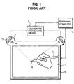
- Fig. 1 shows an example of a conventional digitizer.
- a pen 2 is equipped with an infrared LED 24 at its tip.
- the image of the pen tip luminescent spot is then picked up from two angles by a pair of detecting units 3 on a coordinate plane 1.
- the detecting unit 3 is comprised of a lens 9 and a linear image sensor 13.
- the picked up images then are transformed into electric signals, and these signals are processed at a coordinate processing means 7 using the triangulation principle in order to detect the coordinate of the pen tip.
- a hand-touch on the panel is allowed as long as the hand is not intersecting the path between the pen tip and the image taking means.
- the optical digitizer is further connected to a personal computer 5.
- the computer possesses a display device 6 to display computer output, wherein the display device 6 is arranged in such a way that the coordinate plane 1 and the display surface of the display device 6 coincide.
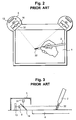
- the detecting unit 3 is configured by adding a tunnel mirror 14 in front of the image formation lens 9 of the linear image sensor 13. They are arranged in such a way that the optical axis of the LED light source 31 and the optical axis of the linear image sensor 13 coincide.
- a tape made of the retroreflective material 22 is rolled around the tip of the pen 2.
- the image taking means is arranged at the position near the apex angle, so the coordinate plane and image taking means are next to each other. This makes, this segment, physically extend out to the side in the actual mounting.
- an optical digitizer using the retroreflective means as shown in Fig. 3, it requires configuration of the optical axis of the image taking means 13, which has a view field close to 90 degrees, and the light source 31 to coincide at a wide field angle, creating the problem of causing the actual mounting to be thick. This is a fatal problem in a portable type computer which requires a compact size.
- the present invention proposes an optical digitizer capable of actually mounting the image taking means in a compact size.
- the invention further aims to reduce the number of image sensors in the detecting unit, which are expensive parts in the optical digitizer, thereby providing an economically efficient optical digitizer.
- the optical digitizer is comprised of a light source to emit a light ray, an image taking means, which is placed at the periphery of the coordinate plane, to pick up the image of the instruction means by using the light ray of the light source and covert it into an electric signal, a computing means to compute the coordinates of the pointed position based on the electric signal converted by the image taking means, and a curved mirror, placed between the light source and the image taking means, in order to widen the field angle of the image of the image taking means.
- the light source is located either at the instruction means itself or between the image taking means and the curved mirror, and by causing the light ray, which is emitted from the light source, to be reflected by the curved mirror, the field angle of the image taking means is widened.
- the retroreflective material is located either at the instruction means itself or at the frame of the coordinate plane. By reflecting the reflected light from the retroreflective material by the curved mirror and sending it to the image taking means, the coordinates of the pointed position of the instruction means are detected.
- a pair of curved mirrors, or a pair of curved mirrors and the image taking means are arranged in such a way that the directions of reflected light from the respective curved mirrors face each other.
- the image of the aforementioned instruction means is taken from different directions, and then the instruction means can be detected by either one image taking means or by two image taking means.
- the optical digitizer of the present invention can have a display device to conduct display output, wherein the display device is arranged in such a way that the aforementioned coordinate plane and the display surface of the display device coincide.
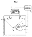
- Fig. 4 is a plane diagram schematically showing the first embodiment of the optical digitizer in accordance with the present invention.
- Curved mirrors 26 are arranged on the right and left sides of the center of the coordinate plane 1 in such a way that the orientations of the reflected light from the curved mirrors 26 are opposed to each other, as shown in the diagram.
- the hyperbolic cylinder mirror is used as the curved mirror.
- the emitted light from the light emitting segment at the tip of the pen 2 in this example, the infrared light, is reflected by the hyperbolic mirror 26, and is incident on the image taking segment composed of the lens 9 and the linear image sensor 13.
- the view field angle of the linear image sensor 13 is widened.
- the image of the pen 2 is taken from the two directions by the respective linear image sensors 13, the respective images of the light emitting segment 24 of the tip of the pen 2 imaged by the lenses 9 are converted to the electric signals by the linear image sensors 13 respectively, and based on these image signals from two directions, the two dimensional coordinates (X, Y) of the pen 2 are determined through the triangular principle computed by the microprocessor in the coordinate computing means 7.
- the linear image sensor is allowed to be folded back toward the inside and, accordingly, the image taking segment can be mounted in a compact size without extending out from the side unlike in the prior art.
- the coordinate computing means 7 is connected to the personal computer 5, equipped with the display device 6 to display the computer output, and the display device 6 is arranged in such a way that the coordinate plane 1 and the display surface of the display device 6 coincide.
- the optical digitizer it becomes possible to use the optical digitizer to write letters directly on top of the display surface, so that it can be used by a doctor to display the medical record of a patient on the display screen and make a handwriting input with a pen.
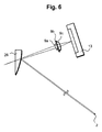
- Fig. 5 illustrates a diagram to show the reflective characteristics of the hyperbolic mirror 26, which is used in the first embodiment of the optical digitizer shown in Fig. 4 in accordance with the present invention.
- the characteristics of the hyperbolic mirror, as shown in Fig. 5, are that the light beams heading for the focus point P reflect off from the curved surface and advance towards another focus point Q, so that by placing a lens at the focus point Q for imaging at the image sensor, it becomes possible to detect the angle of the light beam heading for the focus point P.
- the view field angle of the image taking segment is widened by the hyperbolic mirror, allowing the image of the light beam to be taken from the coordinate plane which is folded back toward the inside with the image taking segment, so that the image taking segment can be mounted in a very compact way compared to the prior art.
- the detection of the coordinates is of two dimensional, so that the cylinder mirror is sufficient, but in the case of detecting three-dimensional coordinates, it is preferred to have a mirror whose revolved section becomes a hyperbolic curve.
- an area image sensor can be employed for the image sensor.
- the curved mirror is not limited to the hyperbolic mirror, and a concave surface mirror, a convex surface mirror, a concave surface cylinder mirror, a convex surface cylinder mirror, and the like may well be used.
- the horizontal level focal point gets blurred.
- the hyperbolic cylinder mirror acts like a concave cylinder lens with a short focal point.
- an aperture with a slit which is narrow in the horizontal direction and long in the vertical direction, can be installed in order to deepen the focal depth in the horizontal direction.
- it is also possible to correct the blurred focal point in the horizontal direction by configuring the imaging lens with a convex cylinder lens 9a, an aperture 9b and a convex lens 9c as shown in Fig. 6.
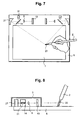
- Fig. 7 is a plane view showing the second embodiment of the optical digitizer in accordance with the present invention.
- the retroreflective material 22 is installed at the tip of the pen 2.
- the LED 31 is arranged in such a way that its light axis is coincided with the light axis of the image taking segment by using the tunnel mirror 14. These are placed on the right and left of the center of the coordinate plane 1 as shown in the diagram.
- the light beam emitted from the LED 31 is reflected by the tunnel mirror 14 and incident on the curved mirror 27.
- an elliptic cylinder mirror is used as a curved mirror to widen the field angle of the light rays.
- the field angle of the light rays is widened by the elliptic cylinder mirror 27, and the light rays go over the coordinate plane 1.
- the light rays incident on the retroreflective material 22 installed on the tip of the pen 2 on the coordinate plane 1, is reflected in the direction exactly the same as the direction for the incidence because of its retroreflective characteristics.
- the returned light ray reflected from the pen 2 goes into the elliptic cylinder mirror 27, goes through the tunnel mirror 14, and makes an image at the linear image sensor 13 by the lens 9.
- the images of the pen 2 from both the right and left directions are converted to electric signals by the respective linear image sensors 13, and from these image signals of the right and left, the 2D coordinates (X, Y) of the pen 2 are determined by using the triangulation principle.
- the light axis of the light source and the image taking segment are coincided by using the tunnel mirror, it is not limited to this.
- a half mirror, a pinhole, or the like can be used, or it is possible to arrange the light source and the image taking segment to be very close to each other.
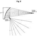
- Fig. 8 is a partial sectional view seen from the side of the optical digitizer shown in Fig. 7.
- the LED as the light source should have been placed above the coordinate plane, i.e., in a vertical direction, as shown in Fig. 2 in order to match the light axis where the field angle is wide, so that a sufficient height for the detecting unit 3 was unavoidably necessary.
- the LED is placed in the horizontal direction, the field angle of the image taking segment will become narrow, and causes the coordinate plane become narrow.
- the present invention allows the LED to be placed in the horizontal direction since the field angle can be widened by the use of the curved mirror. Consequently, as shown in Fig. 8, the thickness of the detecting unit 3 can be very thin. Since the curved mirror widens the field angle towards the coordinate plane, the coordinate plane will not become narrow.
- the prior art required the use of a special type light source which can emit the light rays with a wide angle, which was expensive.
- the present invention allows the use of an inexpensive LED which is commercially available as a general purpose one and the emitted light rays therefrom can be widened to the desired field angle by the curved mirror, so that the device itself can be manufactured at an inexpensive cost.
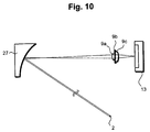
- Fig. 9 is a pattern diagram showing the retroreflective characteristics of the elliptic cylinder mirror shown in Fig. 8. As shown in the diagram, the light ray, which is headed for the focal point P, is reflected and is then headed for another focal point Q, so that the equivalent effect as if it were using the hyperbolic cylinder mirror shown in Fig. 5 can be gained.
- the horizontal level focal point gets blurred.
- the elliptic cylinder mirror acts like a convex cylinder lens with a short focal point.
- an aperture with a slit which is narrow in the horizontal direction and long in the vertical direction, can be installed in order to deepen the focal depth in the horizontal direction.
- the present embodiment uses the curved mirror as the elliptic cylinder mirror, it is not limited to the curved mirror.
- the hyperbolic cylinder mirror can also be used.
- the curved mirror in accordance with the present invention is like the hyperbolic mirror or the elliptic mirror.
- a mirror which has a characteristic of fixing the focal point to two points calculation is easily allowed of the imaging position for the instruction means. It is not limited to such a mirror, and a concave mirror, a convex mirror, a concave cylinder mirror, a convex cylinder mirror and the like which varies its focal point can be used as well.
- the one, which uses the elliptic cylinder mirror as the curved mirror is illustrated and explained here, but other curved mirrors can be used as well.
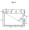
- Fig. 11 is a plane view showing a typical configuration of the third embodiment of the optical digitizer in accordance with the present invention.
- This embodiment is for the optical digitizer which detects the position pointing coordinates of the instruction means 20, and yet does not possess any specific function in itself such as a finger, an instruction stick, or the like.
- a frame comprised of the retroreflective material 4 is installed around the coordinate plane 1.
- an image of the retroreflective material 4, which is located on two sides of the coordinate plane 1 is portrayed at each of the right and left image sensors 13.
- the images of the retroreflective material 4a and 4b, and for the left side image sensor, the images of the retroreflective material 4b and 4c are picked up via the curved mirrors, which widen the field angle of the image sensors.
- an instruction means 20 such as a finger or the like is placed on the coordinate plane 1
- the reflected light ray from the retroreflective material 4 is blocked by the instruction means 20, allowing the image of the shadow 20a to be detected by the image sensor 13, so that the position pointing coordinates of the instruction means 20 can be detected.
- the so-called touch panel system can be realized.
- a lens 9, a tunnel mirror 14, an image sensor 13 and the like can be arranged in such a way to fold back the light rays, so that the image taking segment in accordance with the present invention can be mounted in a very compact size, for example, by placing it within the housing of the existing display device.
- the width of the shadow image 20a can be taken into consideration. Namely, when the width of the shadow image is narrow, it can be judged as a finger or a stick for input processing, and if the width of the shadow image is wider than a predetermined size, it can be judged as a hand-touch, so that the input processing will not be conducted.
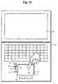
- Fig. 12 is a plane view showing a typical configuration of a fourth embodiment of the optical digitizer in accordance with the present invention.
- the optical digitizer in accordance with the present invention can be made compact by using a curved mirror, thereby making it possible to incorporate the system in a notebook type personal computer 51 as shown in Fig. 12. It is possible to use the third embodiment for this case. In this embodiment, however, through the method of folding back at the plane mirror 42, the LED 31, the tunnel mirror 14, the lens 9, the image taking segment comprised of the linear image sensor 13 and the curved mirror 27 are made into one component. A light ray emitted from the LED 31 is reflected at the tunnel mirror 14, its field view angle is widened by the curved mirror 27, and then incident on the coordinate plane 1.
- This light ray is folded back by the plane mirror 42 and is incident on the retroreflective material 4, then returns in the direction in which the incident ray came from by the retroreflective characteristic.
- the returned light ray which is once again reflected at the plane mirror 42, is then picked up at the linear image sensor 13 by the lens 9.
- an instruction means 20 such as a finger is placed on the coordinate plane 1
- the position pointing coordinates of the instruction means 20 are detected with the triangulation principle from the shadows created by the light ray emitted from the LED 31 and by the light ray folded back at the plane mirror 42.
- This embodiment can improve the operability of a touch panel in accordance with the prior art electrostatic method incorporated in a notebook type personal computer, wherein an input cannot be made smoothly when operated by a dry finger.
- This embodiment also makes an input by a means other than a finger possible, such as a signature input and a handwriting input by a pen. It is possible to make the coordinate plane 1 with a hard material plate, so that even if it is operated with a pen which has a sharp tip, unlike the pad used for the pressure sensitive resistance membrane system, the plate will not be torn.
- the embodiment shown in Fig. 12 has the optical digitizer in accordance with the present invention mounted in the so-called arm-rest area of the notebook type personal computer 51, it is also possible to mount the optical digitizer in accordance with the present invention in the frame area of the display device 6, since it can be made compact by using a curved mirror, thereby allowing operation with a finger or the like directly on top of the display screen.
- the optical digitizer extends over the frame area of the display device 6, making it unsuitable for the notebook type personal computer.
- the optical digitizer in accordance with the present invention can be mounted without enlarging the housing, so that it can fit a personal computer as a space saving design.
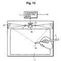
- Fig. 13 is a plane view of a typical configuration of a fifth embodiment of the optical digitizer in accordance with the present invention.
- This embodiment is intended to reduce the cost greatly by reducing the number of linear image sensors which are relatively expensive items.
- the light rays emitted from the light emitting segment 24 installed at the tip of the pen 2 are reflected by the curved mirrors 27 positioned both in the right and the left in order to widen the field view angles of the image taking segments, thus forming images by the lenses 9 respectively, and are incident on the combined mirror 50.
- the combined mirror 50 is arranged in such a way as to shift the position so that the images from two directions will not overlap on the image forming plane of the linear image sensor 13.
- the combined mirror 50 is arranged in such a way as to have the left side image form an image in the left half of the linear image sensor, and the right side image form an image in the right half of the same linear image sensor.
- the image taken from the two directions is converted to an electric signal as the combined image signal of right and left by the linear image sensor 13.
- This signal is analyzed at the coordinate computing means 7 by using the triangulation principle for its computing operation, thereby the position pointing coordinates of the pen 2 can be detected. Since the linear image sensor is divided into half to capture the image from right and left, its resolution becomes half.
- the number of the linear sensors can be reduced, allowing for a substantial cost reduction of the entire system, as well as allowing the size to be even more compact due to the decreased number of the linear image sensors.
- the present invention allows the position of the linear image sensor to be folded back inwardly by the curved mirror, so that the sharing of the linear image sensor for taking the images from the right and left, which was impossible in the prior art, has become possible.
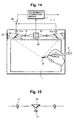
- Fig. 14 is a plane view showing a typical configuration of a sixth embodiment of the optical digitizer in accordance with the present invention.
- This embodiment also intends to reduce the number of the linear image sensors, thereby reducing the cost of the entire system. Unlike the fifth embodiment, however, this embodiment does not divide the image forming plane of one linear image sensor into two; instead, this embodiment allows the resolution of the linear image sensor to be utilized fully.
- the LED 31, the tunnel mirror 14, the curved mirror 27 and the lens 9 are arranged on both the right and left sides as shown in Fig. 14, and the LEDs of the right and left are alternately caused to emit light by a lighting switchover device 60. For example, by the lighting switchover device 60, the left side LED 31a is first caused to emit the light.
- the light ray emitted from the left side LED 31a is reflected at the tunnel mirror 14, and its field view angle is widened by the curved mirror 27, and is incident on the surface of the coordinate plane 1.
- the light ray incident on the retroreflective material installed at the tip of the pen 2 returns in the same direction as that of the incident light ray by the retroreflective characteristic, is reflected by the combined mirror 50 via lens 9, and forms an image on the image forming plane of the linear image sensor 13.
- the image taken from the left side in this way is converted to an electric signal, and inputted into the coordinate computing means 7 as the left side signal.
- the LED for emitting light is switched to the right side LED 31b by the lighting switchover device 60, and in the same manner, through the light ray emitted from the right LED 31b, the image is taken by the linear image sensor 13, which is converted to the electric signal and inputted into the coordinate computing means 7 as the right side signal.
- the above processes are repeated at a high speed, and detection of the images of the right and the left is effected alternately by one image taking means.
- the operational process using the triangulation principle is conducted to gain the position pointing coordinates of the pen 2.
- the lighting switchover device 60 is connected to the coordinate computing means 7 which is capable of detecting as to whether the signal inputted thereto is based on the right LED or the left LED.
- the resolution of the linear image sensor is fully utilized, and at the same time the number of the linear image sensors can be reduced, thereby allowing the cost to be reduced greatly, and the entire system to be more compact with less number of the linear image sensors.
- Fig. 15 is a sectional view of the surrounding area of the combined mirror of the sixth embodiment shown in Fig. 14. As illustrated, the components are configured in such a way that each of the right and the left image is formed by each lens 9, is refracted by the combined mirror 50, and is incident on the linear image sensor 13. By causing the right and left LEDs 31 to emit the light alternately through the lighting switchover device, the images of the right and left can be detected separately by one linear image sensor 13.
- the present invention allows the installation position of the image taking means not to extend out to the side of the coordinate plane and in a compact manner because the light rays can be folded back by the curved mirror.
- the field view angle may be widened by the curved mirror, thereby enabling the image taking means and the light source to be installed at desired locations, thus enabling the provision of a thin-type optical digitizer.
- the curved mirror may widen the light rays, so that a commercially available LED may be used. Consequently, it has become possible for the system to be manufactured at a low cost.
- the present invention enabled one image sensor to take the images from two directions, thereby enabling the manufacturing of the system at low cost.
- optical digitizer of this invention is not limited to the preferred embodiments and modifications described above.
Landscapes
- Engineering & Computer Science (AREA)
- General Engineering & Computer Science (AREA)
- Theoretical Computer Science (AREA)
- Human Computer Interaction (AREA)
- Physics & Mathematics (AREA)
- General Physics & Mathematics (AREA)
- Position Input By Displaying (AREA)
- Length Measuring Devices By Optical Means (AREA)
Applications Claiming Priority (2)
| Application Number | Priority Date | Filing Date | Title |
|---|---|---|---|
| JP32048299 | 1999-11-11 | ||
| JP32048299A JP4054847B2 (ja) | 1999-11-11 | 1999-11-11 | 光デジタイザ |
Publications (1)
| Publication Number | Publication Date |
|---|---|
| EP1100040A2 true EP1100040A2 (fr) | 2001-05-16 |
Family
ID=18121949
Family Applications (1)
| Application Number | Title | Priority Date | Filing Date |
|---|---|---|---|
| EP00309791A Withdrawn EP1100040A2 (fr) | 1999-11-11 | 2000-11-06 | Numérisateur d'image optique utilisant un miroir incurvé |
Country Status (4)
| Country | Link |
|---|---|
| EP (1) | EP1100040A2 (fr) |
| JP (1) | JP4054847B2 (fr) |
| KR (1) | KR20010051563A (fr) |
| CN (1) | CN1296241A (fr) |
Cited By (4)
| Publication number | Priority date | Publication date | Assignee | Title |
|---|---|---|---|---|
| WO2004006170A1 (fr) * | 2002-07-04 | 2004-01-15 | Softronics Co., Ltd. | Systeme de signature multidimensionnelle |
| US7768505B2 (en) | 2005-03-29 | 2010-08-03 | Canon Kabushiki Kaisha | Indicated position recognizing apparatus and information input apparatus having same |
| WO2010122762A1 (fr) | 2009-04-22 | 2010-10-28 | Xiroku, Inc. | Appareil de détection de position optique |
| EP2350794A1 (fr) * | 2008-11-05 | 2011-08-03 | SMART Technologies ULC | Système d'entrée interactif comportant une structure de réflexion multiangle |
Families Citing this family (16)
| Publication number | Priority date | Publication date | Assignee | Title |
|---|---|---|---|---|
| JP2005107607A (ja) * | 2003-09-29 | 2005-04-21 | Eit:Kk | 光学式位置検出装置 |
| KR100623039B1 (ko) * | 2004-04-21 | 2006-09-18 | 와우테크 주식회사 | 광을 이용하는 좌표측정 시스템 |
| KR100615554B1 (ko) * | 2005-01-25 | 2006-08-25 | 한국정보통신대학교 산학협력단 | 초소형 정보기기용 촉각형 정보 입력 시스템 및 장치 |
| KR20060097962A (ko) * | 2005-03-08 | 2006-09-18 | 삼성전자주식회사 | 디스플레이장치 |
| JP4459155B2 (ja) * | 2005-11-14 | 2010-04-28 | 株式会社東芝 | 光学式位置計測装置 |
| KR20080044017A (ko) | 2006-11-15 | 2008-05-20 | 삼성전자주식회사 | 터치 스크린 |
| KR100849322B1 (ko) | 2006-11-20 | 2008-07-29 | 삼성전자주식회사 | 이미지 센서를 이용한 터치 스크린 |
| CN101872270B (zh) * | 2009-04-25 | 2013-09-18 | 鸿富锦精密工业(深圳)有限公司 | 触控装置 |
| KR101604030B1 (ko) | 2009-06-16 | 2016-03-16 | 삼성전자주식회사 | 어레이 방식의 후방 카메라를 이용한 멀티터치 센싱 장치 |
| JP5742398B2 (ja) * | 2011-04-06 | 2015-07-01 | セイコーエプソン株式会社 | 光学式位置検出装置、および入力機能付き表示システム |
| JP2012226412A (ja) * | 2011-04-15 | 2012-11-15 | Seiko Epson Corp | 光学式位置検出装置および入力機能付き表示システム |
| JP5814608B2 (ja) * | 2011-05-02 | 2015-11-17 | キヤノン株式会社 | 座標入力装置及びその制御方法、プログラム |
| KR101359731B1 (ko) * | 2012-03-29 | 2014-02-07 | (주)아이타키온 | 반사부를 이용한 터치인식 시스템 |
| JP6160329B2 (ja) * | 2013-07-24 | 2017-07-12 | 船井電機株式会社 | プロジェクタ |
| KR102215733B1 (ko) * | 2018-06-08 | 2021-02-16 | 주식회사 이미지마이닝 | 레이저를 이용한 인터랙티브 시스템 |
| KR102215734B1 (ko) * | 2018-06-08 | 2021-02-16 | 주식회사 이미지마이닝 | Ir 레이저 기반의 개체 인식을 통한 인터랙티브 시스템 |
-
1999
- 1999-11-11 JP JP32048299A patent/JP4054847B2/ja not_active Expired - Fee Related
-
2000
- 2000-11-06 EP EP00309791A patent/EP1100040A2/fr not_active Withdrawn
- 2000-11-09 KR KR1020000066397A patent/KR20010051563A/ko not_active Application Discontinuation
- 2000-11-13 CN CN00132366A patent/CN1296241A/zh active Pending
Cited By (7)
| Publication number | Priority date | Publication date | Assignee | Title |
|---|---|---|---|---|
| WO2004006170A1 (fr) * | 2002-07-04 | 2004-01-15 | Softronics Co., Ltd. | Systeme de signature multidimensionnelle |
| US7768505B2 (en) | 2005-03-29 | 2010-08-03 | Canon Kabushiki Kaisha | Indicated position recognizing apparatus and information input apparatus having same |
| EP2350794A1 (fr) * | 2008-11-05 | 2011-08-03 | SMART Technologies ULC | Système d'entrée interactif comportant une structure de réflexion multiangle |
| EP2350794A4 (fr) * | 2008-11-05 | 2013-01-09 | Smart Technologies Ulc | Système d'entrée interactif comportant une structure de réflexion multiangle |
| WO2010122762A1 (fr) | 2009-04-22 | 2010-10-28 | Xiroku, Inc. | Appareil de détection de position optique |
| EP2422269A1 (fr) * | 2009-04-22 | 2012-02-29 | Xiroku, Inc. | Appareil de détection de position optique |
| EP2422269A4 (fr) * | 2009-04-22 | 2013-09-18 | Xiroku Inc | Appareil de détection de position optique |
Also Published As
| Publication number | Publication date |
|---|---|
| JP4054847B2 (ja) | 2008-03-05 |
| KR20010051563A (ko) | 2001-06-25 |
| JP2001142630A (ja) | 2001-05-25 |
| CN1296241A (zh) | 2001-05-23 |
Similar Documents
| Publication | Publication Date | Title |
|---|---|---|
| EP1100040A2 (fr) | Numérisateur d'image optique utilisant un miroir incurvé | |
| US8339378B2 (en) | Interactive input system with multi-angle reflector | |
| US8576200B2 (en) | Multiple-input touch panel and method for gesture recognition | |
| US5484966A (en) | Sensing stylus position using single 1-D image sensor | |
| US7534988B2 (en) | Method and system for optical tracking of a pointing object | |
| US7782296B2 (en) | Optical tracker for tracking surface-independent movements | |
| US7583258B2 (en) | Optical tracker with tilt angle detection | |
| US8797446B2 (en) | Optical imaging device | |
| EP1516280A2 (fr) | Appareil et procede destines a saisir des donnees | |
| US20110115904A1 (en) | Object-detecting system | |
| WO2005031554A1 (fr) | Detecteur de position optique | |
| JP2001147776A (ja) | 座標入力/検出装置及び情報記憶媒体 | |
| WO2007131087A2 (fr) | Focalisation efficace de la lumière | |
| WO2011003205A1 (fr) | Désambiguïsation de pointeurs par la formation dune image de multiples zones d'entrée tactile | |
| JP2012173029A (ja) | 光学式位置検出装置および入力機能付き表示システム | |
| US20110095977A1 (en) | Interactive input system incorporating multi-angle reflecting structure | |
| JP2012133452A (ja) | 反射板及び反射フレーム | |
| JP4023979B2 (ja) | 光デジタイザ | |
| US20070241262A1 (en) | Optical sensing unit for an optical input device | |
| JP2013024579A (ja) | 光学式位置検出装置および入力機能付き表示システム | |
| JP3837804B2 (ja) | 光デジタイザ | |
| JP4320101B2 (ja) | 光遮断検出装置および情報表示システム | |
| JP2001290583A (ja) | 座標入力/検出装置及び電子黒板システム | |
| JP2001290604A (ja) | 座標入力/検出装置、電子黒板システム、座標位置検出方法及び記憶媒体 | |
| JP2001356877A (ja) | プレゼンテーション装置 |
Legal Events
| Date | Code | Title | Description |
|---|---|---|---|
| PUAI | Public reference made under article 153(3) epc to a published international application that has entered the european phase |
Free format text: ORIGINAL CODE: 0009012 |
|
| AK | Designated contracting states |
Kind code of ref document: A2 Designated state(s): AT BE CH CY DE DK ES FI FR GB GR IE IT LI LU MC NL PT SE TR |
|
| AX | Request for extension of the european patent |
Free format text: AL;LT;LV;MK;RO;SI |
|
| STAA | Information on the status of an ep patent application or granted ep patent |
Free format text: STATUS: THE APPLICATION HAS BEEN WITHDRAWN |
|
| 18W | Application withdrawn |
Withdrawal date: 20010613 |