EP1099947A2 - Procédé et dispositif pour faire un essai optique d'un pneu - Google Patents
Procédé et dispositif pour faire un essai optique d'un pneuInfo
- Publication number
- EP1099947A2 EP1099947A2 EP00203957A EP00203957A EP1099947A2 EP 1099947 A2 EP1099947 A2 EP 1099947A2 EP 00203957 A EP00203957 A EP 00203957A EP 00203957 A EP00203957 A EP 00203957A EP 1099947 A2 EP1099947 A2 EP 1099947A2
- Authority
- EP
- European Patent Office
- Prior art keywords
- tire
- reflected
- beam splitter
- mirror
- ray
- Prior art date
- Legal status (The legal status is an assumption and is not a legal conclusion. Google has not performed a legal analysis and makes no representation as to the accuracy of the status listed.)
- Withdrawn
Links
- 238000012360 testing method Methods 0.000 title claims abstract description 41
- 230000003287 optical effect Effects 0.000 title abstract description 17
- 238000000034 method Methods 0.000 title description 30
- 230000001427 coherent effect Effects 0.000 claims abstract description 12
- 238000009659 non-destructive testing Methods 0.000 claims description 4
- 239000012530 fluid Substances 0.000 claims 1
- 230000010287 polarization Effects 0.000 abstract description 6
- 238000012545 processing Methods 0.000 abstract description 5
- 238000010008 shearing Methods 0.000 abstract description 4
- 239000002131 composite material Substances 0.000 abstract description 3
- 230000010363 phase shift Effects 0.000 abstract description 2
- 238000012935 Averaging Methods 0.000 abstract 1
- 239000011324 bead Substances 0.000 description 17
- 230000033001 locomotion Effects 0.000 description 13
- 238000000926 separation method Methods 0.000 description 12
- 230000008901 benefit Effects 0.000 description 9
- 238000001093 holography Methods 0.000 description 7
- 238000001444 catalytic combustion detection Methods 0.000 description 6
- 239000013078 crystal Substances 0.000 description 6
- 230000007547 defect Effects 0.000 description 6
- 230000007246 mechanism Effects 0.000 description 6
- 230000008859 change Effects 0.000 description 5
- 238000006073 displacement reaction Methods 0.000 description 5
- 230000035945 sensitivity Effects 0.000 description 5
- 238000010586 diagram Methods 0.000 description 4
- 230000002452 interceptive effect Effects 0.000 description 4
- 238000003384 imaging method Methods 0.000 description 3
- 238000005259 measurement Methods 0.000 description 3
- 230000005855 radiation Effects 0.000 description 3
- 238000004458 analytical method Methods 0.000 description 2
- 238000001514 detection method Methods 0.000 description 2
- 238000005516 engineering process Methods 0.000 description 2
- 239000011152 fibreglass Substances 0.000 description 2
- 238000007689 inspection Methods 0.000 description 2
- 238000002955 isolation Methods 0.000 description 2
- 239000000463 material Substances 0.000 description 2
- 238000003825 pressing Methods 0.000 description 2
- 230000008569 process Effects 0.000 description 2
- 229910000831 Steel Inorganic materials 0.000 description 1
- 230000009471 action Effects 0.000 description 1
- 230000000712 assembly Effects 0.000 description 1
- 238000000429 assembly Methods 0.000 description 1
- 238000012993 chemical processing Methods 0.000 description 1
- 238000010276 construction Methods 0.000 description 1
- 230000008602 contraction Effects 0.000 description 1
- 238000013461 design Methods 0.000 description 1
- 230000001066 destructive effect Effects 0.000 description 1
- 238000011161 development Methods 0.000 description 1
- 230000007613 environmental effect Effects 0.000 description 1
- 239000000835 fiber Substances 0.000 description 1
- 239000011521 glass Substances 0.000 description 1
- 230000010354 integration Effects 0.000 description 1
- 238000004519 manufacturing process Methods 0.000 description 1
- 238000012986 modification Methods 0.000 description 1
- 230000004048 modification Effects 0.000 description 1
- 230000035939 shock Effects 0.000 description 1
- 239000010959 steel Substances 0.000 description 1
Images


Classifications
-
- G—PHYSICS
- G01—MEASURING; TESTING
- G01M—TESTING STATIC OR DYNAMIC BALANCE OF MACHINES OR STRUCTURES; TESTING OF STRUCTURES OR APPARATUS, NOT OTHERWISE PROVIDED FOR
- G01M17/00—Testing of vehicles
- G01M17/007—Wheeled or endless-tracked vehicles
- G01M17/02—Tyres
- G01M17/027—Tyres using light, e.g. infrared, ultraviolet or holographic techniques
Definitions
- This invention relates to the field of nondestructive testing of articles such as tires.
- the invention relates to electronic shearography, which produces interference patterns generated by laterally-displaced images of an object.
- holographic tire testing became the standard for testing tires for critical applications such as aircraft, race cars and truck tires.
- These machines required film cameras to record the extremely fine detail in the laser light interference fringe pattern that makes up the hologram. Sensitive to flaws, these machines required skilled operators and vibration isolation systems to insulate the optical elements and the tire from any motion greater than 1 ⁇ 4 of the wavelength of the laser light during the film exposure.
- the holography camera was located inside a dome which created a test cell into which the tire was placed.
- a vacuum blower or vacuum accumulator connected by valves allowed the machine controller to cycle the pressure inside the test cell from ambient pressure to a reduced vacuum level and back to ambient.
- the heavy steel construction and vibration isolation system reduced vibration and movement of the components sufficiently to obtain holograms of the tire subject to different vacuum loads.
- Shearography is a film based optical technique similar to holography but instead of yielding a fringe pattern showing how the tire changes shape, shearography shows the first derivative of the change in shape. Fringe patterns due to temperature and tire creep were eliminated and only the double bulls eye pattern around the separation flaws remains. Interpretation is far easier and the system is much less sensitive to vibration and other motion problems.
- Air containing separations within the tire are detected when the tire is subjected to a reduced atmospheric pressure, increasing the relative pressure inside the separation stresses the rubber material above the tire.
- the rubber tire material above the separation is forced outward from the inside surface of the tire (or outside surface if on the sidewall area of the tire) towards the shearography camera.
- the shearography camera(s) operate by recording the interferometric image of the tire at an initial pressure state and comparing the image to that of the tire at a reduced pressure.
- the comparison technique may be any of a number of digital or analog image processing techniques well known in the literature including image subtraction, absolute differences, square root of the some of the squares or others in order to obtain an image showing the derivatives of the out of plane displacement.
- the CCD based shearography camera makes 30 video images per second allowing a continuous real-time video image to the tire showing how the tire is deforming.
- Techniques such as image integration and defect depth detection are well known and established techniques.
- a new design feature allowed by the use of small lasers or fiber optic laser beam delivery techniques is to move the camera instead of the tire.
- the lower mass of the camera and support mechanism has a shorter vibration damp time than the mass of a rotation tire and it's support mechanism. This increases the overall speed of the tire tester and economic benefit by having a greater throughput.
- the birefringent shearography optical system As effective as the birefringent shearography optical system is, the amount of the image shear is fixed during the manufacturing of the Wollastan prism. While is can be rotated to make the interferometer sensitive in different vector directions, the shear angle is fixed.
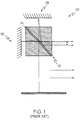
- the Newman, Tyson 5,094,528 patent teaches the use of a shearography optical system using a cube type beam splitter and various mirrors to obtain an fully adjustable sheared image, however this technique has two drawbacks: the beam splitter cube, to bonded right angle prisms, are very heavy and suffer from loss of resolution due to internal reflections. This phenomenon is depicted in FIGURE 1, which depicts a prior art system 10 of the type that is disclosed in U.S.
- Patent 5,094,528 including a cube beam splitter 12 having an interface surface 14, and a pair of reflecting mirrors 16, 18.
- the light paths that define the desired image is represented in FIGURE 1 as solid lines, while the light paths followed by the unwanted internal reflections are depicted as broken lines.
- FIGURE 1 the presence of the unwanted internal reflections can seriously degrade the resolution of the image that is received by the camera.
- the resolution loss places a lower limit on tire defect size sensitivity and detection reliability than can be reliably found.
- Weight is a problem if the camera is mounted on a robotic arm or, in the case of a tire tester, a camera rotation and tilt mechanism.
- an apparatus for the nondestructive testing of a tire includes, according to a first aspect of the invention, a source of coherent light directed onto a portion of a tire being tested; a beam splitter located sufficiently near the portion of the tire being tested so that the beam splitter can receive light reflected from the portion of the tire being tested, the beam splitter comprising a partially silvered surface that is capable of transmitting a first portion of a light ray incident thereon, and reflecting a second portion of the incident light ray; and analyzing structure for comparatively analyzing the first and second portions of light from the beam splitter to produce a shearography image.
- an apparatus 20 includes a laser 22 that is constructed and arranged to direct coherent or monochromatic light onto the surface 24 of a test object, which in the preferred embodiment is a tire, although the invention has applicability to a number of other fields for which shearography might have utility, as will be discussed in greater detail below.
- a beam expander 26 causes the light beam from laser 22 to diverge in the direction of the object to be tested.
- a mirror 28 and beam splitter 30 are positioned near the object, so as to receive light reflected therefrom.
- a detector 32 is positioned near the beam splitter, as shown.
- the detector 32 is preferably a video camera that includes a large number of charge-coupled devices or CCDs, but it can be any device which is capable of detecting an image, virtually instantaneously, for subsequent digital processing.
- the detector includes lens 34 and a photosensitive screen 36. Images are focused onto the screen by the lens 34.
- Detector 32 is connected to a computer 38 which stores the images formed on the screen 36, and processes the stored images digitally in any one of a number of different ways, several of the preferred of which are discussed in greater detail below.
- FIGURE 2 shows how the apparatus 20 performs shearography.
- the beam splitter 30 is embodied as a partially silvered surface or mirror that is capable of transmitting a first portion of a light ray incident thereon, and reflecting a second portion of the incident light ray.
- the surface or mirror is silvered to the extent that it permits about fifty percent of the light incident thereon to be transmitted, with the remaining about fifty percent being reflected.
- the reflected ray from point B strikes beam splitter 30.
- One portion of that ray is reflected from the beam splitter 30, and the remainder, labeled B', is transmitted through the beam splitter 30, also indicated by a dotted line.
- the rays illustrated by the dotted lines (A' and B') are not of concern here.
- the reflected ray is reflected in a direction which coincides with that of the ray originating from point A.
- the reflected rays from points A and B are directed into the same path. Because both rays have been reflected exactly once, after being reflected from the object itself, both rays will have the same angle of polarization. Since their polarization angle is the same, and the wavefronts are parallel, these rays interfere with each other to the maximum extent possible.
- the interfering rays pass through lens 34 which focuses the rays onto screen 36.
- the interfering rays did not have the same angle of polarization, they would interfere only partially. Partial interference reduces the signal-to-noise ratio, as the components of the rays which do not interfere would add to the background signal, causing loss of sensitivity. It is absolutely necessary that the rays have polarization angles which are not mutually orthogonal; otherwise, the rays would not interfere at all. It is preferable that the polarization angles be equal, to maximize the signal-to-noise ratio.
- FIGURE 2 therefore shows that the detector 32 can observe a wide range of points on the object, and is not limited to only a small area.
- the apparatus of FIGURE 2 generates a shearogram, and it does so with a beam splitter that is relatively lightweight and has a high degree of resolution in comparison with a prismatic beam splitter of the type that is described in U.S. Patent 5,094,528.
- the overall amount of light entering the camera or detector 32 is maximized, which is very important for low cost tire testers used in truck tire retreading where the laser is a major expense item.
- This first embodiment is used for lower cost machines for the truck tire industry.
- the disadvantage of this embodiment with respect to the other embodiments described below is that the parallax caused by the having two image apertures separated by a several inches causes a slightly distorted image and requires a laser with a relatively long coherent length (at least equal to the separation of the two imaging apertures).
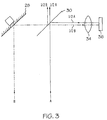
- FIGURE 3 shows only two rays, labeled A and B, reflected from the object (not shown in FIGURE 3). Also, the source of coherent radiation is omitted from FIGURE 3.
- ray A enters beam splitter 30. Approximately one half of ray A is transmitted and the other half is reflected. The reflected ray travels towards lens 34, which focuses the ray onto screen 36. At the same time, ray B is reflected from mirror 28, onto the beam splitter.
- the intensity of the radiation received at the screen 36 can be represented as 0.5A+0.5B. Since A and B are approximately equal (both rays originate from the same source, and are reflected from the same object), it follows that the intensity observed at a point on the screen, due to the interference of two rays, is approximately equal to the intensity of one of the rays reflected from the object. Thus, the amplitude at the detector is of comparable magnitude to the amplitude of the light reflected from the object.
- the above-described feature contrasts with some of the shearography systems of the prior art, wherein the optical elements inherently cause substantial attenuation of the light reflected from the object. By reducing the attenuation, one reduces the power requirements of the laser.
- One requirement of the above-described embodiments of the present invention is that the laser have a relatively long coherent length. In general, the difference between the path lengths of the reflected beams must be no greater than the coherent length of the laser, i.e. the length beyond which the laser beam ceases to be coherent.
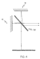
- FIGURE 4 and 5 depict two additional embodiments of the invention.
- the first as shown in FIGURE 4, is the standard Michelson Type interferometer, offering complete adjustability of the shear amount and direction (shear vector) using the partially silvered mirror beam splitter 30.
- the second which is shown in FIGURE 5, is constructed and arranged so that one of the mirrors can be translated in steps to gather three or four shearography images where each image has one leg of the interferometer phase shifted.
- Mirror 40 is linearly movable, as indicated by the arrows.
- Mirror 42 is rotatable, also as indicated by arrows.
- Beam splitter 30, lens 34, and screen 36 are similar to the corresponding components of the other embodiments.
- FIGURE 5 shows rays A and B, which originate from nearby points on the object. (For purposes of simplicity, neither the laser nor the object is shown in FIGURE 5.) A portion of ray A is reflected from the beam splitter 30, and onto mirror 42. A portion of the reflected ray then passes through the beam splitter, towards the lens and screen. At the same time, a portion of ray B passes through the beam splitter 30, and is reflected from mirror 40. A portion of the reflected ray is reflected from the beam splitter 30, towards the lens and screen. Thus, the arrangement of FIGURE 5 generates a shearogram. Note that FIGURE 5 does not show the portions of the rays that are lost due to the beam splitter.
- linear displacement of mirror 40 causes phase shifts, so that the apparatus of FIGURE 4 can be used to practice the method, described above, wherein shearograms are taken at different phase angles.
- Rotation of mirror 42 changes the angle of shear, i.e. the amount of separation of the laterally-displaced images. As mentioned above, varying the amount of shear varies the sensitivity of measurement. Note that the embodiment of FIGURE 5 can be used even where the mirrors are not moved or rotated. Also, it is possible to make mirror 40 rotatable and mirror 42 linearly movable. It is also possible to make both mirrors linearly movable or to make them both rotatable. All of these alternatives are within the scope of the invention.
- the advantage of the embodiment of FIGURE 5, whether or not the mirrors are movable or rotatable, is that the path lengths of the rays originating from points A and B are the same, or almost the same. Therefore, the coherent length requirement of the laser is substantially reduced, as compared with the other embodiments.
- These multiple images may be used to generate a phase map image of a tire 48 (or any object being tested).
- This phase stepping technique is applicable to tire testers where maximum sensitivity to small defects is required.
- Phase stepping techniques are well established in the optical testing industry and would be known to those having ordinary skill in this industry.
- the phase stepping embodiment can be overly sensitive if used where large separations are common.
- the invention can be modified in many ways.
- the particular means of analyzing the shearograms generated by the apparatus of the invention can be varied. It is also possible to vary the order in which shearograms for stressed and unstressed conditions of the object are taken. Additional mirrors can be added, to direct the interfering beams to the detector, if it is necessary to change the position of the detector, subject to the requirement that the total path length of the beams be less than the coherent length of the laser.
- the invention is not limited by the type of laser used, or by the particular structure of the beam splitter.
- the invention can be used to test virtually any kind of opaque or translucent object.
- the invention is not limited to a particular type of detector, and could even be used with a film-based system, if desired.
- the images formed in the detector 32 are stored and processed by computer 38, or its equivalent.
- the processing steps can be essentially the same as those described in U.S. Pat. No. 4,887,899.
- shearograms can be taken while the object is in an unstressed condition, and while the object is stressed. Stressing the object at, say, point A, changes the effective path length of the beam reflected from point A, thus changing the phase angle between the rays reflected from points A and B. This change perturbs the interference pattern, and the change can be observed by comparing the two patterns.
- the shearograms can also be taken while the object is at two different conditions of stress, and is not limited to the special case in which the object is unstressed initially. It is therefore understood, throughout this specification, that wherever it is stated that shearograms are taken with the object in the "stressed” and “unstressed” conditions, the same could be done while the object is subjected to two distinct levels of stress.
- Another useful procedure is to store the shearogram formed while the object is unstressed, and then to form and store shearograms repeatedly, in real time, as the object is stressed.
- the computer 38 is programmed to compare electronically the original shearogram (representing the unstressed condition) with the shearogram taken at a given instant, and to display the instantaneous results of the comparison on a video screen.
- the apparatus can display a "real time" image representing the current state of the object.
- mirror adjuster 44 can be used to vary the position of the mirror. It is understood that adjuster 44, as shown in the figure, represents any device or devices capable of causing linear and/or rotational movements of the mirror. Rotational movements cause variations in the amount of shearing; linear movements vary the path length of the light ray reflected from the mirror, and are useful in the technique described below.
- the mirror adjuster can be a motor, a piezoelectric crystal, or any other device capable of causing large or small movements. Rotation of the mirror changes the set of points "A" which give rise to light which interferes with light from points "B". This is equivalent to saying that the relative displacement of the sheared images is varied. Note that the amount of shearing can thus be continuously varied.
- the ability to vary the linear position of mirror 28 can also be exploited in the following method of analyzing interference patterns.
- the following method reduces "noise" in the final pattern, due to laser speckle.
- a piezoelectric crystal, or equivalent device is used to move the mirror linearly, shifting the phase of the light from set of points "A". Each movement of the mirror is extremely small, i.e. a fraction of a wavelength.
- the mirror is "stepped" through four discrete positions, representing changes in the path length of one-quarter wave length.
- a shearogram is obtained for the first position, and is stored electronically. Then, a shearogram is obtained for each of the four quarter-wave positions while the object is stressed.
- each shearogram is taken for each of the four linear positions of the mirror, each shearogram being stored as before.
- each phase-shifted shearogram is compared with the initial shearogram. That is, the shearogram taken in the first position, while the object is deformed, is compared with the stored shearogram taken while the object is undeformed. The same is done for each of the other mirror positions.
- the four composite patterns are averaged, or otherwise compared, or image processed, to obtain a final pattern.
- the final pattern has reduced speckle "noise".
- the method used to compare the shearograms taken for each given phase angle can simply be the subtraction of one pattern from the other, or it can be any of the other methods described in U.S. Pat. No. 4,887,899, or other methods.
- the number of times the mirror is "stepped” can be varied. In general, the greater the number of "steps", the greater the sensitivity of the method, and the longer the time required to perform the analysis.
- a piezoelectric crystal is preferred because it enables one to move the mirror by very small distances, of the order of a fraction of a wavelength, in a controlled manner, according to a voltage applied to the crystal. Piezoelectric crystals have been used, in other fields, for producing small controlled movements of objects, and such devices are therefore commercially available. However, the above-described method is not limited to the use of a piezoelectric crystal.
- a primary use for the invention is the nondestructive testing of tires for internal separation defects. Any of the three embodiments of the optical system can be used, each having advantages and disadvantages. However, the use of the invention enhances the performance of an electronic shearographic tire tester by reducing the weight of the camera and eliminating internal reflections in the commonly used glass beam splitter cube and the resulting loss of image resolution.
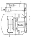
- FIGURE 6 is a schematic drawing of the preferred embodiment of the invention used for the inspection of tires
- the laser 22 that is shown in FIGURE 2 is built into a housing 46 which also contains the shearography apparatus 20 shown in FIGURE 2, including the partially silvered mirror 30, the fully reflective mirror 28, the detector 32 including a CCD video camera, the lens 34 and the imaging CCD chip 36.
- the tire 48 must be subjected to a partial vacuum load by placing it inside a split pressure vessel 50 capable of opening to receive the tire by the action of pneumatic cylinder 52, which is connected to frame 54.
- the pressure vessel 50 consists of two fiberglass domes, an upper dome 46 and a lower dome 56. Inside lower dome 56 is an internal support frame 58, mounted on pneumatic vibration isolators 60.
- pneumatic isolators 60 There can be any number of pneumatic isolators 60 as is sufficient to support the weight of frame 58, tire cart 62 and the weight of the tire 48 to be tested. Typically, three isolators 60 are used so distortions of the fiberglass lower dome 56 caused by the force of the differential pressure inside and outside the dome do not cause distortion of the inner frame 58.
- Shearography tire testing is accomplished by imaging the submicroscopic deformation of the tire caused by the presence of air containing separations, blisters or bonding defects when the tire is subjected to a reduced atmospheric pressure. Therefore, proper handling of the tire while loading into the machine is important. If stresses are put on the tire, the rubber will keep moving for some time, creep, and disrupt the shearographic process.
- the preferred embodiment of the invention minimizes such stresses on the tire by use of a tilt table tire feeder 64 that permits tire 48 to be rolled onto the frame of a tilt table 66. The tire 48 is leaned over onto tire cart 62. The operator presses a button which opens a solenoid valve allowing air pressure to activate an air cylinder pushing the table up to the horizontal position.
- the tire cart 62 is then rolled by the operator into the machine and onto tracks 68 that mounted on inner frame 58.
- the shearography cameras 70 and 72 are mounted on a vertical lift mechanism built into the inner frame and placed into their lower position for loading and unloading the tire.
- the camera lift mechanism can be designed to be rotated in steps around the tire 48, allow sequential testing section by section with the tire 48 stationary, or the tire 48 can be rotated and stopped for section by section testing. Have a lower moment of inertia than the tire 48, tire cart and chain required to rotate the tire 48, rotation the cameras and camera lift mechanism is the preferred but not only embodiment.
- the dome 46 When the tire 48 is in the test position, the dome 46 is closed and the operator enters the tire type/size. Other test parameters such as vacuum level, tire diameter and width are also entered. If the apparatus is fitted with bead cameras, the operator can select bead to bead inspection by crown and one bead followed by a tire flip operation. Most race tires may be inspected bead to bead from the inside due to the wide section width. Pressing a TEST button starts the test sequence. The controller positions the camera to the proper elevation for the test tire and begins the test. The tester automatically evacuates the chamber to the proper test pressure, captures the image, rotates to the next shot and repeats the sequence. Each image is displayed live and at the end of the sequence; a composite of all images is displayed for operator interpretation.
- Images can be stored onto optical disk or a print can be made if the system has the optional video printer.
- the system automatically does the necessary housekeeping of setting the laser interlocks, lowering the bottom camera into the load/unload position. Pressing a button or set up for automatic opening as part of the test may open the dome. The operator has the option of stopping the test at any point.
- the combined tire rotation and camera manipulation motion control is programmed for every tire using a simple teach/learn database. This completely eliminates mechanical adjustments during change over from one tire size to another, allowing random tires sizes to be tested as fast as though they were all one size (assuming an equal number of images per tire at the same vacuum level).
- the tire support frame is shock/vibration isolated from the chamber to eliminate normal factory environmental effects.
- the bottom camera assembly is in a normally retracted position for tire loading and unloading. When the test is started, the camera/laser assembly is elevated to the test position under computer control.
- the system has identical upper and lower camera/laser assemblies. As the tire 48 is rotated is steps under computer control, they inspect the entire tire bead to bead in a single setup.
- the upper camera laser assembly is adjustable to inspect the full range of the upper bead and sidewall.
- the lower camera assembly telescopes upward to inspect the entire inner crown area.
- the exact height of the camera is a function of the tire size and is controlled by the processor through the computer database of tire data.
- the lower bead area is tested with the lower camera/laser assembly in a lowered position or by flipping the tire to obtain full bead to bead coverage. All test sequences and camera positions controlled by the computer from the teach/learn tire database.
- Key areas of the tire 48 that are preferably inspected according to the invention include the crown area 74, the shoulders 76 and 78 as well as the beads and turn-up-ply areas 80 on both side walls of the tire 48. This can be accomplished with two cameras covering the tire 48 in two rotations, or passes around the tire.
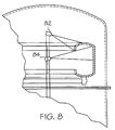
- FIGURE 8 shows the raised position of two shearography cameras 82, 84, one viewing the top bead side wall area, the other viewing the top inside shoulder area down to the crown of the tire.
- the tire or the cameras can be rotated in steps around the tire testing section by section.
- the cameras are then lowered so that the top camera views the inside lower shoulder and the bottom camera views the lower bead area.
- the cameras then drop below the tire to extract the tire from the machine.
- a single camera system for crown areas only, or one camera covering all four band passes around the tire can be built using this invention.
- the tire 48 is positioned with its axis centered over the apertures of the camera(s).
- the cameras are lifted to their test position.
- a vacuum blower 86 is connected by a hose to lower dome 56 so that when this blower is turned on, the air pressure inside the vessel is reduced.
- a solenoid valve is also connected to the lower dome so that when open, air is pulled into the closed vessel and out the exhaust port of the blower. When this valve is closed, the air can no longer enter the vessel to replace the interior air being pumped out causing the internal air pressure to drop.
- the cameras test the tire in four bands, representing the upper bead, upper shoulder, lower shoulder, and lower bead.
- the air pressure inside the vessel and on the tire must be cycle for each test section unless, the cameras can be operated simultaneously, in which case the number of vacuum cycles is equal to the number of test sections divided by the number of cameras.
- Controls 88 for the machine allow for the operator to open and close the upper dome 46, view and evaluate the various test results on areas of the tire on video monitor 90 and store the test images on a device such as an optical disk drive, hard disk drive or video printer.
- upper dome 46 is opened, the tilt table 66 lifted to the tire load position, the tire cart 62 rolled out onto the tilt table 66 and the tilt table 66 lowered. The tire tester is then ready for the next tire.
Applications Claiming Priority (2)
| Application Number | Priority Date | Filing Date | Title |
|---|---|---|---|
| US43896699A | 1999-11-12 | 1999-11-12 | |
| US438966 | 1999-11-12 |
Publications (2)
| Publication Number | Publication Date |
|---|---|
| EP1099947A2 true EP1099947A2 (fr) | 2001-05-16 |
| EP1099947A3 EP1099947A3 (fr) | 2003-01-29 |
Family
ID=23742757
Family Applications (1)
| Application Number | Title | Priority Date | Filing Date |
|---|---|---|---|
| EP00203957A Withdrawn EP1099947A3 (fr) | 1999-11-12 | 2000-11-10 | Procédé et dispositif pour faire un essai optique d'un pneu |
Country Status (1)
| Country | Link |
|---|---|
| EP (1) | EP1099947A3 (fr) |
Cited By (7)
| Publication number | Priority date | Publication date | Assignee | Title |
|---|---|---|---|---|
| US6959602B2 (en) | 2002-03-19 | 2005-11-01 | Millipore Corporation | Ultrasonic detection of porous medium characteristics |
| EP1355142A3 (fr) * | 2002-04-16 | 2006-02-08 | Steinbichler Optotechnik Gmbh | Dispositif d'essai de pneu |
| EP1500917A3 (fr) * | 2003-07-24 | 2006-05-10 | Steinbichler Optotechnik Gmbh | Procédé et dispositif d'essai de pneus |
| EP1936349A2 (fr) | 2006-12-22 | 2008-06-25 | Bernward Mähner | Dispositif d'essai d'un objet à tester, en particulier d'un pneu, à l'aide d'un procédé de mesure non-destructif |
| EP2026056A2 (fr) | 2007-08-13 | 2009-02-18 | Steinbichler Optotechnik Gmbh | Dispositif d'essai de pneu |
| EP1959227A3 (fr) * | 2007-02-16 | 2010-12-22 | Bernward Mähner | Dispositif et procédé destinés à la vérification d'un pneu, en particulier à l'aide d'un procédé de mesure interférométrique |
| CN109100354A (zh) * | 2017-06-21 | 2018-12-28 | 波音公司 | 用于光学检查系统的高速真空循环激励系统 |
Citations (6)
| Publication number | Priority date | Publication date | Assignee | Title |
|---|---|---|---|---|
| US4139302A (en) * | 1977-02-17 | 1979-02-13 | Dr. Ralph M. Grant Engineering Consultants, Inc. | Method and apparatus for interferometric deformation analysis |
| US4702594A (en) * | 1982-11-15 | 1987-10-27 | Industrial Holographics, Inc. | Double exposure interferometric analysis of structures and employing ambient pressure stressing |
| EP0324872A1 (fr) * | 1988-01-19 | 1989-07-26 | Albert Reiff KG | Procédé et dispositif d'essai non destructif des pneus de véhicules |
| US5094528A (en) * | 1990-05-25 | 1992-03-10 | Laser Technology, Inc. | Apparatus and method for performing electronic shearography |
| US5165080A (en) * | 1987-09-11 | 1992-11-17 | British Telecommunications Public Limited Company | Optical distributor |
| DE19748544C1 (de) * | 1997-11-03 | 1999-07-08 | Ettemeyer Gmbh & Co Mes Und Pr | Verfahren und Vorrichtung zur Prüfung von elastischen konkaven Gegenständen |
-
2000
- 2000-11-10 EP EP00203957A patent/EP1099947A3/fr not_active Withdrawn
Patent Citations (6)
| Publication number | Priority date | Publication date | Assignee | Title |
|---|---|---|---|---|
| US4139302A (en) * | 1977-02-17 | 1979-02-13 | Dr. Ralph M. Grant Engineering Consultants, Inc. | Method and apparatus for interferometric deformation analysis |
| US4702594A (en) * | 1982-11-15 | 1987-10-27 | Industrial Holographics, Inc. | Double exposure interferometric analysis of structures and employing ambient pressure stressing |
| US5165080A (en) * | 1987-09-11 | 1992-11-17 | British Telecommunications Public Limited Company | Optical distributor |
| EP0324872A1 (fr) * | 1988-01-19 | 1989-07-26 | Albert Reiff KG | Procédé et dispositif d'essai non destructif des pneus de véhicules |
| US5094528A (en) * | 1990-05-25 | 1992-03-10 | Laser Technology, Inc. | Apparatus and method for performing electronic shearography |
| DE19748544C1 (de) * | 1997-11-03 | 1999-07-08 | Ettemeyer Gmbh & Co Mes Und Pr | Verfahren und Vorrichtung zur Prüfung von elastischen konkaven Gegenständen |
Cited By (17)
| Publication number | Priority date | Publication date | Assignee | Title |
|---|---|---|---|---|
| US6959602B2 (en) | 2002-03-19 | 2005-11-01 | Millipore Corporation | Ultrasonic detection of porous medium characteristics |
| EP1355142A3 (fr) * | 2002-04-16 | 2006-02-08 | Steinbichler Optotechnik Gmbh | Dispositif d'essai de pneu |
| EP1500917A3 (fr) * | 2003-07-24 | 2006-05-10 | Steinbichler Optotechnik Gmbh | Procédé et dispositif d'essai de pneus |
| US7360410B2 (en) | 2003-07-24 | 2008-04-22 | Steinbichler Optotechnik Gmbh | Procedure and device for testing tires |
| CN101206182B (zh) * | 2006-12-22 | 2012-06-13 | 伯尼沃德·梅尼尔 | 借助无损检测法检验被检物尤其是轮胎的装置 |
| EP1936349A3 (fr) * | 2006-12-22 | 2009-07-01 | Bernward Mähner | Dispositif d'essai d'un objet à tester, en particulier d'un pneu, à l'aide d'un procédé de mesure non-destructif |
| EP2450688A1 (fr) * | 2006-12-22 | 2012-05-09 | Bernward Mähner | Dispositif d'essai d'un objet à tester, en particulier d'un pneu, à l'aide d'un procédé de mesure non-destructif |
| EP1936349A2 (fr) | 2006-12-22 | 2008-06-25 | Bernward Mähner | Dispositif d'essai d'un objet à tester, en particulier d'un pneu, à l'aide d'un procédé de mesure non-destructif |
| EP1959227A3 (fr) * | 2007-02-16 | 2010-12-22 | Bernward Mähner | Dispositif et procédé destinés à la vérification d'un pneu, en particulier à l'aide d'un procédé de mesure interférométrique |
| CN101245987B (zh) * | 2007-02-16 | 2011-03-23 | 伯尼沃德·梅尼尔 | 尤其借助干涉测量法检测轮胎的装置和方法 |
| EP2026056A2 (fr) | 2007-08-13 | 2009-02-18 | Steinbichler Optotechnik Gmbh | Dispositif d'essai de pneu |
| JP2009047691A (ja) * | 2007-08-13 | 2009-03-05 | Steinbichler Optotechnik Gmbh | タイヤ試験施設 |
| EP2026056A3 (fr) * | 2007-08-13 | 2010-12-29 | Steinbichler Optotechnik GmbH | Dispositif d'essai de pneu |
| EP2549258A1 (fr) * | 2007-08-13 | 2013-01-23 | Steinbichler Optotechnik GmbH | Dispositif d'essai de pneu |
| EP2549258B1 (fr) | 2007-08-13 | 2018-12-05 | Carl Zeiss Optotechnik GmbH | Dispositif d'essai de pneu |
| CN109100354A (zh) * | 2017-06-21 | 2018-12-28 | 波音公司 | 用于光学检查系统的高速真空循环激励系统 |
| CN109100354B (zh) * | 2017-06-21 | 2023-02-21 | 波音公司 | 用于光学检查系统的高速真空循环激励系统 |
Also Published As
| Publication number | Publication date |
|---|---|
| EP1099947A3 (fr) | 2003-01-29 |
Similar Documents
| Publication | Publication Date | Title |
|---|---|---|
| JP4611393B2 (ja) | タイヤ試験装置及び方法 | |
| US4702594A (en) | Double exposure interferometric analysis of structures and employing ambient pressure stressing | |
| US5094528A (en) | Apparatus and method for performing electronic shearography | |
| US4869593A (en) | Interferometric surface profiler | |
| US7856869B2 (en) | Device and method for checking a tire in particular by means of an interferometric measuring method | |
| EP0473173A2 (fr) | Procédé et dispositif de détection de fuites d'un emballage | |
| FR2490341A1 (fr) | Procede et dispositif pour indiquer une contrainte dans un objet | |
| WO2006093752A1 (fr) | Pluralite de sources lumineuses pour appareil et procede d'inspection | |
| JP2003529743A (ja) | スキャン、繋ぎ合わせ、および防振を含む両面計測検査具での測定 | |
| EP1099947A2 (fr) | Procédé et dispositif pour faire un essai optique d'un pneu | |
| US8074506B2 (en) | Apparatus and method for testing a tire | |
| WO1997034124A1 (fr) | Detection de surface optique de disques magnetiques | |
| CN113767277A (zh) | 用于对样品表面进行检查的正入射相移偏转测量传感器、系统和方法 | |
| US5448352A (en) | Method and apparatus for the nondestructive testing of vessels made of composite material wound on a metallic liner by means of holographic interferometry | |
| JPS62500468A (ja) | 測定対象物における静応力の測定装置および測定方法 | |
| US5786896A (en) | Oblique incidence interferometer with fringe scan drive | |
| US3690159A (en) | Holographic interferometry employing image plane holograms | |
| US7911618B2 (en) | Holographic interferometry for non-destructive testing of power sources | |
| US6606160B1 (en) | Nondestructive testing of diffusely reflective objects | |
| NO322717B1 (no) | System og fremgangsmate for maling av egenskaper i eller under overflaten til et materiale, samt anvendelse av dette | |
| Zheng et al. | Development of Digital Shearography for Dual Sensitivity Simultaneous Measurement Using Carrier Frequency Spatial Phase Shift Technology | |
| SU1117445A1 (ru) | Способ голографического неразрушающего контрол механических дефектов | |
| KR102243446B1 (ko) | 다중대역 광학계 검사장치 및 검사방법 | |
| RU2776397C2 (ru) | Способ измерения кривизны отражающей поверхности и соответствующее оптическое устройство | |
| JPH10122833A (ja) | 表面測定装置 |
Legal Events
| Date | Code | Title | Description |
|---|---|---|---|
| PUAI | Public reference made under article 153(3) epc to a published international application that has entered the european phase |
Free format text: ORIGINAL CODE: 0009012 |
|
| AK | Designated contracting states |
Kind code of ref document: A2 Designated state(s): AT BE CH CY DE DK ES FI FR GB GR IE IT LI LU MC NL PT SE TR |
|
| AX | Request for extension of the european patent |
Free format text: AL;LT;LV;MK;RO;SI |
|
| PUAL | Search report despatched |
Free format text: ORIGINAL CODE: 0009013 |
|
| AK | Designated contracting states |
Designated state(s): AT BE CH CY DE DK ES FI FR GB GR IE IT LI LU MC NL PT SE TR |
|
| AX | Request for extension of the european patent |
Extension state: AL LT LV MK RO SI |
|
| RIC1 | Information provided on ipc code assigned before grant |
Ipc: 7G 01B 9/02 B Ipc: 7G 01B 11/16 B Ipc: 7G 01M 17/02 A |
|
| AKX | Designation fees paid |
Designated state(s): AT BE CH CY DE DK ES FI FR GB GR IE IT LI LU MC NL PT SE TR |
|
| STAA | Information on the status of an ep patent application or granted ep patent |
Free format text: STATUS: THE APPLICATION IS DEEMED TO BE WITHDRAWN |
|
| 18D | Application deemed to be withdrawn |
Effective date: 20030730 |