EP1099774B1 - Procédé de fabriction d'un élément en matériau composite - Google Patents
Procédé de fabriction d'un élément en matériau composite Download PDFInfo
- Publication number
- EP1099774B1 EP1099774B1 EP99830693A EP99830693A EP1099774B1 EP 1099774 B1 EP1099774 B1 EP 1099774B1 EP 99830693 A EP99830693 A EP 99830693A EP 99830693 A EP99830693 A EP 99830693A EP 1099774 B1 EP1099774 B1 EP 1099774B1
- Authority
- EP
- European Patent Office
- Prior art keywords
- metal wires
- reinforcing
- main body
- metal
- compacting
- Prior art date
- Legal status (The legal status is an assumption and is not a legal conclusion. Google has not performed a legal analysis and makes no representation as to the accuracy of the status listed.)
- Expired - Lifetime
Links
Images


Classifications
-
- C—CHEMISTRY; METALLURGY
- C22—METALLURGY; FERROUS OR NON-FERROUS ALLOYS; TREATMENT OF ALLOYS OR NON-FERROUS METALS
- C22C—ALLOYS
- C22C47/00—Making alloys containing metallic or non-metallic fibres or filaments
- C22C47/02—Pretreatment of the fibres or filaments
- C22C47/025—Aligning or orienting the fibres
-
- C—CHEMISTRY; METALLURGY
- C22—METALLURGY; FERROUS OR NON-FERROUS ALLOYS; TREATMENT OF ALLOYS OR NON-FERROUS METALS
- C22C—ALLOYS
- C22C47/00—Making alloys containing metallic or non-metallic fibres or filaments
-
- C—CHEMISTRY; METALLURGY
- C22—METALLURGY; FERROUS OR NON-FERROUS ALLOYS; TREATMENT OF ALLOYS OR NON-FERROUS METALS
- C22C—ALLOYS
- C22C47/00—Making alloys containing metallic or non-metallic fibres or filaments
- C22C47/02—Pretreatment of the fibres or filaments
- C22C47/06—Pretreatment of the fibres or filaments by forming the fibres or filaments into a preformed structure, e.g. using a temporary binder to form a mat-like element
- C22C47/062—Pretreatment of the fibres or filaments by forming the fibres or filaments into a preformed structure, e.g. using a temporary binder to form a mat-like element from wires or filaments only
- C22C47/068—Aligning wires
-
- B—PERFORMING OPERATIONS; TRANSPORTING
- B22—CASTING; POWDER METALLURGY
- B22F—WORKING METALLIC POWDER; MANUFACTURE OF ARTICLES FROM METALLIC POWDER; MAKING METALLIC POWDER; APPARATUS OR DEVICES SPECIALLY ADAPTED FOR METALLIC POWDER
- B22F2998/00—Supplementary information concerning processes or compositions relating to powder metallurgy
-
- Y—GENERAL TAGGING OF NEW TECHNOLOGICAL DEVELOPMENTS; GENERAL TAGGING OF CROSS-SECTIONAL TECHNOLOGIES SPANNING OVER SEVERAL SECTIONS OF THE IPC; TECHNICAL SUBJECTS COVERED BY FORMER USPC CROSS-REFERENCE ART COLLECTIONS [XRACs] AND DIGESTS
- Y10—TECHNICAL SUBJECTS COVERED BY FORMER USPC
- Y10T—TECHNICAL SUBJECTS COVERED BY FORMER US CLASSIFICATION
- Y10T29/00—Metal working
- Y10T29/49—Method of mechanical manufacture
- Y10T29/49316—Impeller making
- Y10T29/49336—Blade making
- Y10T29/49337—Composite blade
-
- Y—GENERAL TAGGING OF NEW TECHNOLOGICAL DEVELOPMENTS; GENERAL TAGGING OF CROSS-SECTIONAL TECHNOLOGIES SPANNING OVER SEVERAL SECTIONS OF THE IPC; TECHNICAL SUBJECTS COVERED BY FORMER USPC CROSS-REFERENCE ART COLLECTIONS [XRACs] AND DIGESTS
- Y10—TECHNICAL SUBJECTS COVERED BY FORMER USPC
- Y10T—TECHNICAL SUBJECTS COVERED BY FORMER US CLASSIFICATION
- Y10T29/00—Metal working
- Y10T29/49—Method of mechanical manufacture
- Y10T29/49801—Shaping fiber or fibered material
-
- Y—GENERAL TAGGING OF NEW TECHNOLOGICAL DEVELOPMENTS; GENERAL TAGGING OF CROSS-SECTIONAL TECHNOLOGIES SPANNING OVER SEVERAL SECTIONS OF THE IPC; TECHNICAL SUBJECTS COVERED BY FORMER USPC CROSS-REFERENCE ART COLLECTIONS [XRACs] AND DIGESTS
- Y10—TECHNICAL SUBJECTS COVERED BY FORMER USPC
- Y10T—TECHNICAL SUBJECTS COVERED BY FORMER US CLASSIFICATION
- Y10T428/00—Stock material or miscellaneous articles
- Y10T428/12—All metal or with adjacent metals
- Y10T428/12493—Composite; i.e., plural, adjacent, spatially distinct metal components [e.g., layers, joint, etc.]
Definitions
- the present invention relates to a method of producing elements of composite material, in particular, circular-geometry elements such as countershafts, turbine and compressor disks for turbomachines, etc.
- composite-material elements of the above type are produced by forming a number of disks, each formed by winding a continuous reinforcing fiber about an axis to form a flat spiral; stacking the disks with the interposition of respective spacer sheets of metal material; and axially compacting the stack to form a metal matrix in which the various spirals of reinforcing fibers are embedded.
- the physical characteristics of such composite-material elements depend mainly on the distribution of the reinforcing fibers inside the metal matrix; and the extent to which the fibers are distributed evenly depends on the extent to which the turns in each disk are equally spaced a predetermined distance apart, and the extent to which the freedom of movement of the various turns is restricted, especially at the compacting stage.
- the turns of reinforcing fiber are locked in place with respect to one another by fastening wires wound about each turn and extending spokefashion with respect to the axis of the spiral.
- the turns are equally spaced a given distance apart by forming, alongside formation of the spiral, a further two flat spirals of spacer wire, which are removed from the spiral of reinforcing fiber once the fastening wires are wound about the turns.
- the above method comprises various fairly complex, and therefore fairly high-cost, operations (weaving the spirals of reinforcing wire separately and fastening the relative turns; stacking the disks of ceramic material and spacer sheets; and placing the stacks inside a final container to form the composite-material elements).
- the spacer sheets are not easy to procure in the form required by the methods described, i.e. of constant 0.1 mm thickness, and call for various dedicated machining operations (cutting, grinding, welding, etc.) which further increase the already high cost involved.
- fastening wires must be made of inert material, with respect to both the metal matrix and the reinforcing fibers.
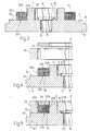
- Number 1 in Figure 1 indicates as a whole an element of composite material formed using the method according to the present invention - in the example shown, a rotary member, such as a compressor disk for turbomachines, to which the following description refers purely by way of example.
- Element 1 is of circular annular shape with an axis of symmetry A, and comprises a central portion 2 in the form of a flat disk and defining a through hole 3 of axis A, and a substantially cylindrical peripheral portion 4 projecting axially in both directions with respect to central portion 2 and supporting externally a number of projecting radial blades 5.
- central portion 2 is made of a composite material defined by a matrix of metal material
- Peripheral portion 4 is made entirely of metal material, advantageously the same material as the matrix of central portion 2.
- Element 1 is formed by preparing and then compacting a toroidal base structure 6 ( Figure 6) of axis A.
- Structure 6 is formed from a substantially annular main body 7 ( Figures 2, 4-9) comprising a through hole 8 of axis A defining hole 3 of element 1, and a disk-shaped portion 9, from a flat end surface 10, perpendicular to axis A, of which projects axially a cylindrical tubular portion 11 having an outside diameter smaller than the outside diameter of disk-shaped portion 9.
- Hole 8 is defined at portions 9 and 11 by respective cylindrical surfaces 12, 13 having different diameters and connected to each other by a flat intermediate surface 14 perpendicular to axis A and extending along an extension of end surface 10. More specifically, cylindrical surface 12 is larger in diameter than cylindrical surface 13.
- Main body 7 also comprises an annular projection 15, of axis A, projecting inside hole 8 from intermediate surface 14 and having a right-triangular section with the hypotenuse facing cylindrical surface 13.
- Base structure 6 is formed as follows.
- a first distribution of metal wires 20 defining the metal matrix of element 1, and a second distribution of fibers 21 of ceramic material defining the reinforcing structure of element 1 are positioned coaxially on main body 7.
- the first distribution is formed by assigning each fiber 21 an orderly distribution of metal wires 20.
- Wires 20 and fibers 21 together define a composite-material ring 16 ( Figure 2) woven on a known winding machine not shown.
- wires 20 and fibers 21 are annular with a circular section ( Figure 3) and are made respectively of titanium alloy and silicon carbide.
- ring 16 is positioned coaxially about tubular portion 11 of main body 7, and rests on end surface 10 of disk-shaped portion 9.
- Wires 20 and fibers 21 are advantageously combined in a weave pattern ( Figure 3) in which two wires 20 are interposed between each pair of fibers 21. More specifically, in the weave pattern, each fiber 21 is surrounded by six wires 20 forming the vertices of a hexagon, and occupies the barycenter of the hexagon.
- Ring 16 is defined externally by a radially outer and radially inner cylindrical lateral surface 22a, 22b, and by two opposite flat annular end surfaces 22c, 22d; which surfaces 22a, 22b, 22c, 22d are made exclusively of metal wires 20 for ensuring, after the compacting step, the structural continuity of ring 16, main body 7 and the other metal parts of structure 6 described in detail later on.
- Wires 20 and fibers 21 have the same diameter and together define a number of hexagonal base cells 18 (shown by the dash lines in Figure 3); and each base cell 18 is defined by a central fiber 21 and by respective 120° angular portions of the six wires 20 surrounding central fiber 21, so that the volume of the reinforcing structure is 33% that of the matrix.
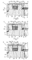
- Structure 6 is completed by fitting main body 7 coaxially with two annular closing elements 23, 24 ( Figures 4 and 5) and a cover 25 ( Figure 6), which, together with main body 7, define a closed seat for ring 16.
- closing element 23 is the same axial height as tubular portion 11 of main body 7, while the axial height of closing element (or piston ring) 24 equals the difference between the axial heights of tubular portion 11 and ring 16.
- Closing element 23 is fitted onto the radially outer surface 22a of ring 16 so as to rest on end surface 10 of disk-shaped portion 9 of main body 7; and, similarly, closing element 24 is inserted between tubular portion 11 of main body 7 and closing element 23 so as to rest on end surface 22d of ring 16, on the opposite side to disk-shaped portion 9.
- Cover 25 comprises a circular, annular, disk-shaped wall 28, from the radially inner and outer peripheral edges of which project respective concentric inner and outer cylindrical walls 29, 30.
- Cover 25 is assembled by positioning disk-shaped wall 28 facing respective free axial ends of closing elements 23, 24 and tubular portion 11 of main body 7, and by inserting cylindrical wall 29 inside hole 8 so that the end rests on projection 15, and by fitting cylindrical wall 30 on the outside of closing element 23 so that the end rests on a peripheral annular shoulder 31 of disk-shaped portion 9 of main body 7 ( Figure 6).
- Cover 25 is then fixed to main body 7 by spot welding the portions contacting projection 15 and shoulder 31.
- the air inside structure 6 is extracted using a known molecular pump (not shown) and a known muffle furnace (not shown) for heating structure 6 to a temperature of about 600°C.
- the resulting structure 6 is compacted in a conventional autoclave (not shown) for HIPping (Hot Isostatic Pressing) processing with automatic temperature and pressure control.
- the temperature of the autoclave is increased to the superplasticity temperature of the titanium alloy - in the example described, about 900°C.
- the temperature in the autoclave is then maintained constant long enough to enable the entire mass defining structure 6 to reach a uniform temperature.
- This period of time - two hours on average - is calculated bearing in mind that heat transmission at this stage is slowed down by the absence of air inside structure 6, and by the fact that the contact area between wires 20 of surfaces 22a, 22b, 22c, 22d of ring 16 and main body 7 is extremely small and therefore permits very little heating by conduction of wires 20.
- the pressure inside the environment housing structure 6 and defined by the autoclave is increased to such a threshold value - in the example described, 900 Kg/cm2 - as to permanently deform disk-shaped wall 28 of cover 25 in a direction parallel to axis A ( Figure 7).
- disk-shaped wall 28 of cover 25 flexes so as to come to rest on closing element 24, which in turn presses against composite-material ring 16 to act as a pressure equalizer and transmitter.
- metal wires 20 are deformed so as to fill the gaps formerly present between wires 20 and fibers 21.
- composite-material ring 16 contracts along axis A, while the position of fibers 21 with respect to axis A remains constant to ensure uniform distribution of the reinforcing structure inside the metal matrix.
- the compacted structure 6 is then cooled by so reducing the temperature and pressure as to minimize the residual stress produced in the portion derived from composite-material ring 16 by the different coefficients of thermal expansion of the metal matrix and reinforcing fibers 21.
- element 1 derived from ring 16 assumes the Figure 10 configuration, in which fibers 21 are evenly distributed inside the metal matrix, are equally spaced in a direction perpendicular to axis A, and are separated by varying distances in a direction parallel to axis A.
- the compacted structure 6 may be subjected to mechanical machining or similar to obtain the finished contour of element 1.
- blades 5 are formed from the part of compacted structure 6 derived from disk-shaped portion 9 of main body 7.
- metal wires 20 to form the matrix of composite-material element 1 therefore provides, by appropriately selecting the diameter of wires 20 and fibers 21, for obtaining any desired distribution of the reinforcing structure inside the metal matrix.
- the freedom of movement of fibers 21 can be limited during compaction to maintain the positions of fibers 21 with respect to axis A.
- the method described provides for forming composite-material element 1 by weaving wires 20 and fibers 21 directly onto parts (main body 7) eventually forming part of the metal matrix of element 1, thus eliminating the need for producing separate disks of reinforcing wire, fastening the turns of each disk, the long, complicated process of stacking the disks with respective metal spacer sheets in between, and placing the stacks inside containers for producing elements 1.
- the spacer sheets which are particularly expensive when titanium-based, and the work involved in preparing the sheets may therefore be eliminated with considerable saving.
- contraction of structure 6 at the compacting stage is less than that of stacks of ceramic disks and metal spacer sheets using the known methods described previously.
- reinforcing fibers 21 may be made of different materials, including metal.
- Main body 7, closing elements 23, 24 and cover 25 may be made of different metal materials from each other and from the material of wires 20.
- composite-material ring 16 may even be extracted from structure 6 and used to form different composite-material elements.
Landscapes
- Chemical & Material Sciences (AREA)
- Engineering & Computer Science (AREA)
- Materials Engineering (AREA)
- Mechanical Engineering (AREA)
- Metallurgy (AREA)
- Organic Chemistry (AREA)
- Crystallography & Structural Chemistry (AREA)
- Manufacture Of Alloys Or Alloy Compounds (AREA)
- Transition And Organic Metals Composition Catalysts For Addition Polymerization (AREA)
Claims (13)
- Procédé de fabrication d'un élément en matériau composite (1) comprenant une matrice métallique et une structure de renforcement, ledit procédé comprenant les étapes de :- formation d'une première distribution de fils métalliques (20) définissant ladite matrice, et d'une seconde distribution de fibres de renforcement (21) définissant ladite structure de renforcement ; ladite étape de formation de ladite première distribution comprenant l'étape d'allocation à chaque dite fibre de renforcement (21) une distribution ordonnée desdits fils métalliques (20) ; ladite étape d'allocation comprenant l'étape de préparation d'un élément tissé (16) en plaçant au moins un dit fil métallique (20) le long de chaque dite fibre de renforcement (21) ; lesdits fils métalliques (20) et lesdites fibres de renforcement (21) étant annulaires ; ladite étape de préparation dudit élément tissé (16) étant exécutée en plaçant lesdits fils métalliques (20) et lesdites fibres de renforcement (21) autour d'un corps principal toroïdal (7) fabriqué en matériau métallique ;- formation d'une structure de base (6) en montant des moyens formant couverture (23, 24, 25) en matériau métallique sur ledit corps principal (7) pour serrer ledit élément tissé (16) entre ledit corps principal (7) et lesdits moyens formant couverture (23, 24, 25) ; et- compression desdits fils métalliques (20) et desdites fibres de renforcement (21) pour obtenir une distribution de ladite structure de renforcement à l'intérieur de ladite matrice ; ladite étape de compression comprenant :- une première phase de compression pour compresser dans le sens axial ledit élément tissé (16), de sorte que lesdits fils métalliques (20) sont déformés de manière à remplir les espaces anciennement présents entre lesdits fils métalliques (20) et lesdites fibres de renforcement (21) ; et- une seconde phase de compression ultérieure pour compresser l'ensemble de ladite structure de base (6) dans toutes les directions pour lier ensemble l'élément tissé (16) compressé dans le sens axial, ledit corps principal (7) et lesdits moyens formant couverture (23, 24, 25).
- Procédé selon la revendication 1, caractérisé en ce que ladite première phase de compression est réalisée tandis que ledit élément tissé (16) est serré entre ledit corps principal (7) et lesdits moyens formant couverture (23, 24, 25).
- Procédé selon la revendication 2, caractérisé en ce que ladite étape de compression comprend les étapes de :- placement de ladite structure de base (6) dans un environnement présentant des conditions de température et de pression pouvant être contrôlées ; et- modification de la température dudit environnement de manière à amener lesdits fils métalliques (20), ledit corps principal (7) et lesdits moyens formant couverture (23, 24, 25) de manière uniforme à une température de superplasticité ;ladite seconde phase de compression étant réalisée en augmentant la pression dans ledit environnement par rapport à la pression de ladite première phase de compression.
- Procédé selon la revendication 3, caractérisé en ce que la pression de ladite première phase de compression présente une valeur de manière à ne déformer en permanence qu'une partie des moyens formant couverture (25) dans une direction parallèle à l'axe (A) dudit corps principal (7).
- Procédé selon l'une quelconque des revendications précédentes, caractérisé en ce que ladite étape de préparation dudit élément tissé (16) comprend l'étape d'interposition d'au moins deux desdits fils métalliques (20) entre chaque paire desdites fibres de renforcement (21) adjacentes.
- Procédé selon l'une quelconque des revendications précédentes, caractérisé en ce que ladite étape de préparation dudit élément tissé (16) comprend l'étape consistant à entourer chaque dite fibre de renforcement (21) avec six dits fils métalliques (20) formant les sommets d'un hexagone.
- Procédé selon la revendication 6, caractérisé en ce que ladite étape de préparation dudit élément tissé (16) comprend l'étape de positionnement de chaque dite fibre de renforcement (21) au barycentre de l'hexagone défini par lesdits fils métalliques (20) autour de la fibre de renforcement (21).
- Procédé selon l'une quelconque des revendications précédentes, caractérisé en ce que ladite étape de préparation dudit élément tissé (16) comprend l'étape de formation de surfaces limites (22a, 22b, 22c, 22d) respectives de l'élément tissé (16) en utilisant exclusivement lesdits fils métalliques (20).
- Procédé selon l'une quelconque des revendications précédentes, caractérisé en ce que ledit corps principal (7) et lesdits moyens formant couverture (23, 24, 25) définissent, à la fin de ladite étape de compression, des portions périphériques respectives dudit élément en matériau composite (1) ; et en ce que ledit élément tissé (16) définit, à la fin de ladite étape de compression, une partie centrale dudit élément en matériau composite (1).
- Procédé selon l'une quelconque des revendications précédentes, caractérisé en ce que lesdits fils métalliques sont fabriqués dans un matériau à base d'un alliage de titane.
- Procédé selon l'une quelconque des revendications précédentes, caractérisé en ce que lesdites fibres de renforcement sont fabriquées en matériau céramique.
- Procédé selon la revendication 11, caractérisé en ce que lesdites fibres de renforcement sont fabriquées dans un matériau à base de carbure de silicium.
- Elément rotatif (1) fabriqué en matériau composite selon le procédé de la revendication 8, l'élément rotatif comprenant une structure en matériau métallique (4) et un élément de renforcement (2, 16) en matériau composite ; caractérisé en ce que ledit élément de renforcement (2, 16) est obtenu à partir d'une distribution ordonnée de fils métalliques (20) et de fibres de renforcement (21), et présente des surfaces limites (22a, 22b, 22c, 22d) respectives fabriquées exclusivement à partir desdits fils métalliques (20) et raccordées intégralement par compression à ladite structure en matériau métallique (4) ; lesdites fibres de renforcement (21) étant espacées les unes des autres.
Priority Applications (6)
| Application Number | Priority Date | Filing Date | Title |
|---|---|---|---|
| DE69930748T DE69930748T2 (de) | 1999-11-04 | 1999-11-04 | Verfahren zur Herstellung eines Bauteiles aus Verbundwerkstoff |
| EP99830693A EP1099774B1 (fr) | 1999-11-04 | 1999-11-04 | Procédé de fabriction d'un élément en matériau composite |
| AT99830693T ATE322560T1 (de) | 1999-11-04 | 1999-11-04 | Verfahren zur herstellung eines bauteiles aus verbundwerkstoff |
| US09/699,741 US6658715B1 (en) | 1999-11-04 | 2000-10-30 | Method of producing an element of composite material |
| CA002325212A CA2325212C (fr) | 1999-11-04 | 2000-11-02 | Methode de production d'un element de materiau composite |
| JP2000337820A JP2001234307A (ja) | 1999-11-04 | 2000-11-06 | 複合材料から成るエレメントの形成方法 |
Applications Claiming Priority (1)
| Application Number | Priority Date | Filing Date | Title |
|---|---|---|---|
| EP99830693A EP1099774B1 (fr) | 1999-11-04 | 1999-11-04 | Procédé de fabriction d'un élément en matériau composite |
Publications (2)
| Publication Number | Publication Date |
|---|---|
| EP1099774A1 EP1099774A1 (fr) | 2001-05-16 |
| EP1099774B1 true EP1099774B1 (fr) | 2006-04-05 |
Family
ID=8243658
Family Applications (1)
| Application Number | Title | Priority Date | Filing Date |
|---|---|---|---|
| EP99830693A Expired - Lifetime EP1099774B1 (fr) | 1999-11-04 | 1999-11-04 | Procédé de fabriction d'un élément en matériau composite |
Country Status (6)
| Country | Link |
|---|---|
| US (1) | US6658715B1 (fr) |
| EP (1) | EP1099774B1 (fr) |
| JP (1) | JP2001234307A (fr) |
| AT (1) | ATE322560T1 (fr) |
| CA (1) | CA2325212C (fr) |
| DE (1) | DE69930748T2 (fr) |
Families Citing this family (16)
| Publication number | Priority date | Publication date | Assignee | Title |
|---|---|---|---|---|
| GB0324810D0 (en) * | 2003-10-24 | 2003-11-26 | Rolls Royce Plc | A method of manufacturing a fibre reinforced metal matrix composite article |
| GB0327044D0 (en) * | 2003-11-18 | 2004-04-07 | Rolls Royce Plc | A method of manufacturing a fibre reinforced metal matrix composite article and a cassette for use therein |
| GB0327002D0 (en) * | 2003-11-20 | 2003-12-24 | Rolls Royce Plc | A method of manufacturing a fibre reinforced metal matrix composite article |
| DE102004001260A1 (de) * | 2004-01-08 | 2005-08-04 | Mtu Aero Engines Gmbh | Rotor für eine Turbomaschine und Verfahren zur Herstellung eines solchen Rotors |
| US7118063B2 (en) * | 2004-07-29 | 2006-10-10 | Sequa Corporation | Wire/fiber ring and method for manufacturing the same |
| FR2886290B1 (fr) * | 2005-05-27 | 2007-07-13 | Snecma Moteurs Sa | Procede de fabrication d'une piece avec un insert en materiau composite a matrice metallique et fibres ceramiques |
| FR2925895B1 (fr) * | 2007-12-28 | 2010-02-05 | Messier Dowty Sa | Procede de fabrication d'une piece metallique renforcee de fibres ceramiques |
| FR2933422B1 (fr) * | 2008-07-04 | 2011-05-13 | Messier Dowty Sa | Procede de fabrication d'une piece metallique comportant des renforts internes formes de fibres ceramiques |
| US9080448B2 (en) | 2009-12-29 | 2015-07-14 | Rolls-Royce North American Technologies, Inc. | Gas turbine engine vanes |
| GB201005270D0 (en) * | 2010-03-30 | 2010-05-12 | Rolls Royce Plc | A method and apparatus for manufacturing a rotor disc |
| FR2970266B1 (fr) | 2011-01-10 | 2013-12-06 | Snecma | Procede de fabrication d'une piece metallique annulaire monobloc a insert de renfort en materiau composite, et piece obtenue |
| FR2971961B1 (fr) * | 2011-02-25 | 2014-06-13 | Snecma | Procede de fabrication d'une piece metallique |
| FR2972124B1 (fr) * | 2011-03-01 | 2014-05-16 | Snecma | Procede de realisation d'une piece metallique telle qu'un renfort d'aube de turbomachine |
| FR2972123B1 (fr) | 2011-03-02 | 2014-06-13 | Snecma | Procede pour fabriquer une piece metallique de revolution monobloc incorporant un renfort de fibres ceramiques |
| FR2972661B1 (fr) * | 2011-03-15 | 2013-04-12 | Snecma | Procede pour fabriquer une piece metallique de revolution monobloc a partir de structures fibreuses composites |
| FR2975317B1 (fr) * | 2011-05-18 | 2013-05-31 | Snecma | Procede de fabrication par soudage diffusion d'une piece monobloc pour une turbomachine |
Family Cites Families (11)
| Publication number | Priority date | Publication date | Assignee | Title |
|---|---|---|---|---|
| BE682999A (fr) * | 1965-06-25 | 1966-12-23 | ||
| US3864807A (en) * | 1970-12-02 | 1975-02-11 | Rau Fa G | Method of manufacturing a shaped element of fiber-reinforced material |
| JPS525656A (en) * | 1975-07-02 | 1977-01-17 | Setsuo Yamamoto | Method of manufacture of fiberrreinforced metal |
| US5431984A (en) * | 1990-12-11 | 1995-07-11 | Avco Corporation | Composite preforms with groves for fibers and groves for off-gassing |
| US5337940A (en) * | 1990-12-11 | 1994-08-16 | Woods Harlan L | Composite preform and method of manufacturing fiber reinforced composite |
| FR2713662B1 (fr) * | 1993-12-08 | 1996-01-12 | Snecma | Procédé d'obtention d'une pièce circulaire métallique renforcée par des fibres. |
| FR2713663B1 (fr) * | 1993-12-15 | 1996-01-12 | Snecma | Procédé de fabrication de pièces axisymétriques en composite à matrice métallique. |
| FR2715883B1 (fr) * | 1994-02-10 | 1996-03-29 | Snecma | Procédé d'obtention d'une pièce circulaire métallique renforcée par des fibres. |
| WO1998011265A1 (fr) * | 1996-09-12 | 1998-03-19 | Minnesota Mining And Manufacturing Company | Bande de materiau composite a matrice metallique |
| GB9619890D0 (en) * | 1996-09-24 | 1996-11-06 | Rolls Royce Plc | A method of making a fibre reinforced metal component |
| IT1289707B1 (it) * | 1996-12-03 | 1998-10-16 | Fiatavio Spa | Metodo e macchina per la realizzazione di un elemento a disco in filo continuo ed elemento a disco realizzato con tale metodo. |
-
1999
- 1999-11-04 EP EP99830693A patent/EP1099774B1/fr not_active Expired - Lifetime
- 1999-11-04 AT AT99830693T patent/ATE322560T1/de not_active IP Right Cessation
- 1999-11-04 DE DE69930748T patent/DE69930748T2/de not_active Expired - Lifetime
-
2000
- 2000-10-30 US US09/699,741 patent/US6658715B1/en not_active Expired - Lifetime
- 2000-11-02 CA CA002325212A patent/CA2325212C/fr not_active Expired - Fee Related
- 2000-11-06 JP JP2000337820A patent/JP2001234307A/ja active Pending
Also Published As
| Publication number | Publication date |
|---|---|
| DE69930748T2 (de) | 2006-11-02 |
| CA2325212C (fr) | 2009-08-25 |
| ATE322560T1 (de) | 2006-04-15 |
| JP2001234307A (ja) | 2001-08-31 |
| CA2325212A1 (fr) | 2001-05-04 |
| EP1099774A1 (fr) | 2001-05-16 |
| US6658715B1 (en) | 2003-12-09 |
| DE69930748D1 (de) | 2006-05-18 |
Similar Documents
| Publication | Publication Date | Title |
|---|---|---|
| EP1099774B1 (fr) | Procédé de fabriction d'un élément en matériau composite | |
| US5400505A (en) | Method for manufacturing fiber-reinforced components for propulsion plants | |
| EP2028165B9 (fr) | Four pour fabriquer une préforme de verre ou une fibre optique | |
| US5305520A (en) | Method of making fibre reinforced metal component | |
| US8065799B2 (en) | Method of fabricating a turbomachine rotor disk | |
| EP1527842B1 (fr) | Procédé de fabrication d'un article composite métallique renforcé par de fibres | |
| US7334999B2 (en) | Turbomachine rotor including at least one disk reinforced by a composite ring | |
| GB2247492A (en) | A method of making a fibre reinforced metal component | |
| US8448837B2 (en) | Method for manufacturing a one-piece annular metal part having a reinforcing insert of composite material | |
| EP1288324B1 (fr) | Méthode de fabrication d'un composant métallique renforcé par des fibres | |
| US8495810B2 (en) | Process for manufacturing a metal part reinforced with ceramic fibres | |
| JP6030124B2 (ja) | タービンエンジン用の単一片部品を拡散接合によって製作する方法 | |
| US7694910B2 (en) | Wire/fiber ring and method for manufacturing the same | |
| WO2000065115A2 (fr) | Systeme de materiau composite renforce de fibres | |
| EP0384629A2 (fr) | Articles composites et procédé pour leur préparation | |
| GB2196566A (en) | Producing reinforced articles |
Legal Events
| Date | Code | Title | Description |
|---|---|---|---|
| PUAI | Public reference made under article 153(3) epc to a published international application that has entered the european phase |
Free format text: ORIGINAL CODE: 0009012 |
|
| AK | Designated contracting states |
Kind code of ref document: A1 Designated state(s): AT BE CH CY DE DK ES FI FR GB GR IE IT LI LU MC NL PT SE |
|
| AX | Request for extension of the european patent |
Free format text: AL;LT;LV;MK;RO;SI |
|
| 17P | Request for examination filed |
Effective date: 20011115 |
|
| AKX | Designation fees paid |
Free format text: AT BE CH CY DE DK ES FI FR GB GR IE IT LI LU MC NL PT SE |
|
| RAP1 | Party data changed (applicant data changed or rights of an application transferred) |
Owner name: FIATAVIO S.P.A. |
|
| RAP1 | Party data changed (applicant data changed or rights of an application transferred) |
Owner name: AVIO S.P.A. |
|
| 17Q | First examination report despatched |
Effective date: 20040219 |
|
| GRAP | Despatch of communication of intention to grant a patent |
Free format text: ORIGINAL CODE: EPIDOSNIGR1 |
|
| GRAS | Grant fee paid |
Free format text: ORIGINAL CODE: EPIDOSNIGR3 |
|
| RAP1 | Party data changed (applicant data changed or rights of an application transferred) |
Owner name: AVIO S.P.A. |
|
| GRAA | (expected) grant |
Free format text: ORIGINAL CODE: 0009210 |
|
| AK | Designated contracting states |
Kind code of ref document: B1 Designated state(s): AT BE CH CY DE DK ES FI FR GB GR IE IT LI LU MC NL PT SE |
|
| PG25 | Lapsed in a contracting state [announced via postgrant information from national office to epo] |
Ref country code: NL Free format text: LAPSE BECAUSE OF FAILURE TO SUBMIT A TRANSLATION OF THE DESCRIPTION OR TO PAY THE FEE WITHIN THE PRESCRIBED TIME-LIMIT Effective date: 20060405 Ref country code: LI Free format text: LAPSE BECAUSE OF FAILURE TO SUBMIT A TRANSLATION OF THE DESCRIPTION OR TO PAY THE FEE WITHIN THE PRESCRIBED TIME-LIMIT Effective date: 20060405 Ref country code: IT Free format text: LAPSE BECAUSE OF FAILURE TO SUBMIT A TRANSLATION OF THE DESCRIPTION OR TO PAY THE FEE WITHIN THE PRESCRIBED TIME-LIMIT;WARNING: LAPSES OF ITALIAN PATENTS WITH EFFECTIVE DATE BEFORE 2007 MAY HAVE OCCURRED AT ANY TIME BEFORE 2007. THE CORRECT EFFECTIVE DATE MAY BE DIFFERENT FROM THE ONE RECORDED. Effective date: 20060405 Ref country code: FI Free format text: LAPSE BECAUSE OF FAILURE TO SUBMIT A TRANSLATION OF THE DESCRIPTION OR TO PAY THE FEE WITHIN THE PRESCRIBED TIME-LIMIT Effective date: 20060405 Ref country code: CH Free format text: LAPSE BECAUSE OF FAILURE TO SUBMIT A TRANSLATION OF THE DESCRIPTION OR TO PAY THE FEE WITHIN THE PRESCRIBED TIME-LIMIT Effective date: 20060405 Ref country code: BE Free format text: LAPSE BECAUSE OF FAILURE TO SUBMIT A TRANSLATION OF THE DESCRIPTION OR TO PAY THE FEE WITHIN THE PRESCRIBED TIME-LIMIT Effective date: 20060405 Ref country code: AT Free format text: LAPSE BECAUSE OF FAILURE TO SUBMIT A TRANSLATION OF THE DESCRIPTION OR TO PAY THE FEE WITHIN THE PRESCRIBED TIME-LIMIT Effective date: 20060405 |
|
| REG | Reference to a national code |
Ref country code: GB Ref legal event code: FG4D |
|
| REG | Reference to a national code |
Ref country code: CH Ref legal event code: EP |
|
| REG | Reference to a national code |
Ref country code: IE Ref legal event code: FG4D |
|
| REF | Corresponds to: |
Ref document number: 69930748 Country of ref document: DE Date of ref document: 20060518 Kind code of ref document: P |
|
| PG25 | Lapsed in a contracting state [announced via postgrant information from national office to epo] |
Ref country code: SE Free format text: LAPSE BECAUSE OF FAILURE TO SUBMIT A TRANSLATION OF THE DESCRIPTION OR TO PAY THE FEE WITHIN THE PRESCRIBED TIME-LIMIT Effective date: 20060705 Ref country code: DK Free format text: LAPSE BECAUSE OF FAILURE TO SUBMIT A TRANSLATION OF THE DESCRIPTION OR TO PAY THE FEE WITHIN THE PRESCRIBED TIME-LIMIT Effective date: 20060705 |
|
| PG25 | Lapsed in a contracting state [announced via postgrant information from national office to epo] |
Ref country code: ES Free format text: LAPSE BECAUSE OF FAILURE TO SUBMIT A TRANSLATION OF THE DESCRIPTION OR TO PAY THE FEE WITHIN THE PRESCRIBED TIME-LIMIT Effective date: 20060716 |
|
| PG25 | Lapsed in a contracting state [announced via postgrant information from national office to epo] |
Ref country code: PT Free format text: LAPSE BECAUSE OF FAILURE TO SUBMIT A TRANSLATION OF THE DESCRIPTION OR TO PAY THE FEE WITHIN THE PRESCRIBED TIME-LIMIT Effective date: 20060905 |
|
| NLV1 | Nl: lapsed or annulled due to failure to fulfill the requirements of art. 29p and 29m of the patents act | ||
| REG | Reference to a national code |
Ref country code: CH Ref legal event code: PL |
|
| PG25 | Lapsed in a contracting state [announced via postgrant information from national office to epo] |
Ref country code: IE Free format text: LAPSE BECAUSE OF NON-PAYMENT OF DUE FEES Effective date: 20061106 |
|
| ET | Fr: translation filed | ||
| PG25 | Lapsed in a contracting state [announced via postgrant information from national office to epo] |
Ref country code: MC Free format text: LAPSE BECAUSE OF NON-PAYMENT OF DUE FEES Effective date: 20061130 |
|
| PLBE | No opposition filed within time limit |
Free format text: ORIGINAL CODE: 0009261 |
|
| STAA | Information on the status of an ep patent application or granted ep patent |
Free format text: STATUS: NO OPPOSITION FILED WITHIN TIME LIMIT |
|
| REG | Reference to a national code |
Ref country code: GB Ref legal event code: 732E |
|
| 26N | No opposition filed |
Effective date: 20070108 |
|
| REG | Reference to a national code |
Ref country code: FR Ref legal event code: GC |
|
| REG | Reference to a national code |
Ref country code: GB Ref legal event code: 732E |
|
| PG25 | Lapsed in a contracting state [announced via postgrant information from national office to epo] |
Ref country code: GR Free format text: LAPSE BECAUSE OF FAILURE TO SUBMIT A TRANSLATION OF THE DESCRIPTION OR TO PAY THE FEE WITHIN THE PRESCRIBED TIME-LIMIT Effective date: 20060706 |
|
| PG25 | Lapsed in a contracting state [announced via postgrant information from national office to epo] |
Ref country code: LU Free format text: LAPSE BECAUSE OF NON-PAYMENT OF DUE FEES Effective date: 20061104 |
|
| PG25 | Lapsed in a contracting state [announced via postgrant information from national office to epo] |
Ref country code: CY Free format text: LAPSE BECAUSE OF FAILURE TO SUBMIT A TRANSLATION OF THE DESCRIPTION OR TO PAY THE FEE WITHIN THE PRESCRIBED TIME-LIMIT Effective date: 20060405 |
|
| REG | Reference to a national code |
Ref country code: FR Ref legal event code: TP Ref country code: FR Ref legal event code: GC Ref country code: FR Ref legal event code: CD |
|
| REG | Reference to a national code |
Ref country code: GB Ref legal event code: 732E Free format text: REGISTERED BETWEEN 20120830 AND 20120905 |
|
| REG | Reference to a national code |
Ref country code: FR Ref legal event code: GC Effective date: 20120905 Ref country code: FR Ref legal event code: AU Effective date: 20120905 |
|
| REG | Reference to a national code |
Ref country code: DE Ref legal event code: R082 Ref document number: 69930748 Country of ref document: DE Representative=s name: ANDREJEWSKI - HONKE PATENT- UND RECHTSANWAELTE, DE Effective date: 20131212 Ref country code: DE Ref legal event code: R081 Ref document number: 69930748 Country of ref document: DE Owner name: GE AVIO S.R.L., IT Free format text: FORMER OWNER: AVIO S.P.A., TORINO, IT Effective date: 20131212 |
|
| REG | Reference to a national code |
Ref country code: FR Ref legal event code: RG Effective date: 20140207 |
|
| REG | Reference to a national code |
Ref country code: GB Ref legal event code: 732E Free format text: REGISTERED BETWEEN 20140828 AND 20140903 |
|
| REG | Reference to a national code |
Ref country code: FR Ref legal event code: TP Owner name: GE AVIO S.R.L., IT Effective date: 20150310 |
|
| REG | Reference to a national code |
Ref country code: FR Ref legal event code: PLFP Year of fee payment: 17 |
|
| REG | Reference to a national code |
Ref country code: FR Ref legal event code: PLFP Year of fee payment: 18 |
|
| REG | Reference to a national code |
Ref country code: FR Ref legal event code: PLFP Year of fee payment: 19 |
|
| REG | Reference to a national code |
Ref country code: FR Ref legal event code: PLFP Year of fee payment: 20 |
|
| PGFP | Annual fee paid to national office [announced via postgrant information from national office to epo] |
Ref country code: DE Payment date: 20181023 Year of fee payment: 20 |
|
| PGFP | Annual fee paid to national office [announced via postgrant information from national office to epo] |
Ref country code: FR Payment date: 20181024 Year of fee payment: 20 Ref country code: IT Payment date: 20181023 Year of fee payment: 20 Ref country code: GB Payment date: 20181024 Year of fee payment: 20 |
|
| REG | Reference to a national code |
Ref country code: DE Ref legal event code: R082 Ref document number: 69930748 Country of ref document: DE Representative=s name: HAFNER & KOHL PATENT- UND RECHTSANWAELTE PARTN, DE Ref country code: DE Ref legal event code: R082 Ref document number: 69930748 Country of ref document: DE Representative=s name: HAFNER & KOHL PATENTANWALTSKANZLEI RECHTSANWAL, DE |
|
| REG | Reference to a national code |
Ref country code: DE Ref legal event code: R071 Ref document number: 69930748 Country of ref document: DE |
|
| REG | Reference to a national code |
Ref country code: GB Ref legal event code: PE20 Expiry date: 20191103 |
|
| PG25 | Lapsed in a contracting state [announced via postgrant information from national office to epo] |
Ref country code: GB Free format text: LAPSE BECAUSE OF EXPIRATION OF PROTECTION Effective date: 20191103 |