EP1099611A2 - Druckmittelbetätigte Fahrzeugbremsanlage - Google Patents
Druckmittelbetätigte Fahrzeugbremsanlage Download PDFInfo
- Publication number
- EP1099611A2 EP1099611A2 EP00122298A EP00122298A EP1099611A2 EP 1099611 A2 EP1099611 A2 EP 1099611A2 EP 00122298 A EP00122298 A EP 00122298A EP 00122298 A EP00122298 A EP 00122298A EP 1099611 A2 EP1099611 A2 EP 1099611A2
- Authority
- EP
- European Patent Office
- Prior art keywords
- valve
- pressure
- control
- brake
- brake circuit
- Prior art date
- Legal status (The legal status is an assumption and is not a legal conclusion. Google has not performed a legal analysis and makes no representation as to the accuracy of the status listed.)
- Granted
Links
- 238000005192 partition Methods 0.000 claims description 12
- 241001295925 Gegenes Species 0.000 description 2
- 230000001419 dependent effect Effects 0.000 description 1
- 238000011161 development Methods 0.000 description 1
- 230000018109 developmental process Effects 0.000 description 1
- 238000010586 diagram Methods 0.000 description 1
- 230000005484 gravity Effects 0.000 description 1
- 239000002655 kraft paper Substances 0.000 description 1
- 230000001105 regulatory effect Effects 0.000 description 1
- 230000028838 turning behavior Effects 0.000 description 1
- 238000013022 venting Methods 0.000 description 1
Images


Classifications
-
- B—PERFORMING OPERATIONS; TRANSPORTING
- B60—VEHICLES IN GENERAL
- B60T—VEHICLE BRAKE CONTROL SYSTEMS OR PARTS THEREOF; BRAKE CONTROL SYSTEMS OR PARTS THEREOF, IN GENERAL; ARRANGEMENT OF BRAKING ELEMENTS ON VEHICLES IN GENERAL; PORTABLE DEVICES FOR PREVENTING UNWANTED MOVEMENT OF VEHICLES; VEHICLE MODIFICATIONS TO FACILITATE COOLING OF BRAKES
- B60T8/00—Arrangements for adjusting wheel-braking force to meet varying vehicular or ground-surface conditions, e.g. limiting or varying distribution of braking force
- B60T8/32—Arrangements for adjusting wheel-braking force to meet varying vehicular or ground-surface conditions, e.g. limiting or varying distribution of braking force responsive to a speed condition, e.g. acceleration or deceleration
- B60T8/88—Arrangements for adjusting wheel-braking force to meet varying vehicular or ground-surface conditions, e.g. limiting or varying distribution of braking force responsive to a speed condition, e.g. acceleration or deceleration with failure responsive means, i.e. means for detecting and indicating faulty operation of the speed responsive control means
- B60T8/92—Arrangements for adjusting wheel-braking force to meet varying vehicular or ground-surface conditions, e.g. limiting or varying distribution of braking force responsive to a speed condition, e.g. acceleration or deceleration with failure responsive means, i.e. means for detecting and indicating faulty operation of the speed responsive control means automatically taking corrective action
- B60T8/94—Arrangements for adjusting wheel-braking force to meet varying vehicular or ground-surface conditions, e.g. limiting or varying distribution of braking force responsive to a speed condition, e.g. acceleration or deceleration with failure responsive means, i.e. means for detecting and indicating faulty operation of the speed responsive control means automatically taking corrective action on a fluid pressure regulator
-
- B—PERFORMING OPERATIONS; TRANSPORTING
- B60—VEHICLES IN GENERAL
- B60T—VEHICLE BRAKE CONTROL SYSTEMS OR PARTS THEREOF; BRAKE CONTROL SYSTEMS OR PARTS THEREOF, IN GENERAL; ARRANGEMENT OF BRAKING ELEMENTS ON VEHICLES IN GENERAL; PORTABLE DEVICES FOR PREVENTING UNWANTED MOVEMENT OF VEHICLES; VEHICLE MODIFICATIONS TO FACILITATE COOLING OF BRAKES
- B60T13/00—Transmitting braking action from initiating means to ultimate brake actuator with power assistance or drive; Brake systems incorporating such transmitting means, e.g. air-pressure brake systems
- B60T13/10—Transmitting braking action from initiating means to ultimate brake actuator with power assistance or drive; Brake systems incorporating such transmitting means, e.g. air-pressure brake systems with fluid assistance, drive, or release
- B60T13/66—Electrical control in fluid-pressure brake systems
- B60T13/68—Electrical control in fluid-pressure brake systems by electrically-controlled valves
- B60T13/683—Electrical control in fluid-pressure brake systems by electrically-controlled valves in pneumatic systems or parts thereof
-
- B—PERFORMING OPERATIONS; TRANSPORTING
- B60—VEHICLES IN GENERAL
- B60T—VEHICLE BRAKE CONTROL SYSTEMS OR PARTS THEREOF; BRAKE CONTROL SYSTEMS OR PARTS THEREOF, IN GENERAL; ARRANGEMENT OF BRAKING ELEMENTS ON VEHICLES IN GENERAL; PORTABLE DEVICES FOR PREVENTING UNWANTED MOVEMENT OF VEHICLES; VEHICLE MODIFICATIONS TO FACILITATE COOLING OF BRAKES
- B60T15/00—Construction arrangement, or operation of valves incorporated in power brake systems and not covered by groups B60T11/00 or B60T13/00
- B60T15/02—Application and release valves
- B60T15/18—Triple or other relay valves which allow step-wise application or release and which are actuated by brake-pipe pressure variation to connect brake cylinders or equivalent to compressed air or vacuum source or atmosphere
- B60T15/24—Triple or other relay valves which allow step-wise application or release and which are actuated by brake-pipe pressure variation to connect brake cylinders or equivalent to compressed air or vacuum source or atmosphere controlled by three fluid pressures
-
- B—PERFORMING OPERATIONS; TRANSPORTING
- B60—VEHICLES IN GENERAL
- B60T—VEHICLE BRAKE CONTROL SYSTEMS OR PARTS THEREOF; BRAKE CONTROL SYSTEMS OR PARTS THEREOF, IN GENERAL; ARRANGEMENT OF BRAKING ELEMENTS ON VEHICLES IN GENERAL; PORTABLE DEVICES FOR PREVENTING UNWANTED MOVEMENT OF VEHICLES; VEHICLE MODIFICATIONS TO FACILITATE COOLING OF BRAKES
- B60T8/00—Arrangements for adjusting wheel-braking force to meet varying vehicular or ground-surface conditions, e.g. limiting or varying distribution of braking force
-
- B—PERFORMING OPERATIONS; TRANSPORTING
- B60—VEHICLES IN GENERAL
- B60T—VEHICLE BRAKE CONTROL SYSTEMS OR PARTS THEREOF; BRAKE CONTROL SYSTEMS OR PARTS THEREOF, IN GENERAL; ARRANGEMENT OF BRAKING ELEMENTS ON VEHICLES IN GENERAL; PORTABLE DEVICES FOR PREVENTING UNWANTED MOVEMENT OF VEHICLES; VEHICLE MODIFICATIONS TO FACILITATE COOLING OF BRAKES
- B60T8/00—Arrangements for adjusting wheel-braking force to meet varying vehicular or ground-surface conditions, e.g. limiting or varying distribution of braking force
- B60T8/32—Arrangements for adjusting wheel-braking force to meet varying vehicular or ground-surface conditions, e.g. limiting or varying distribution of braking force responsive to a speed condition, e.g. acceleration or deceleration
- B60T8/321—Arrangements for adjusting wheel-braking force to meet varying vehicular or ground-surface conditions, e.g. limiting or varying distribution of braking force responsive to a speed condition, e.g. acceleration or deceleration deceleration
- B60T8/3255—Systems in which the braking action is dependent on brake pedal data
- B60T8/327—Pneumatic systems
Definitions
- the invention is based on a pressure-operated vehicle brake system according to the preamble of claim 1.
- Such a vehicle brake system is known from EP 0 726 190 B1 known.
- the known brake system is intended for a commercial vehicle and has a pneumatically operated rear axle brake circuit for the two wheels of the rear axle and one pneumatically operated Front axle brake circuit for the front axle. If the one brake circuit, the other brake circuit is still the commercial vehicle delay sufficiently.
- the rear axle brake circuit has two spring-loaded brake cylinders (Combined brake cylinder) assigned to trained brake cylinders, dependent on a first control valve device from a control signal assigned to the rear axle brake circuit Multi-circuit brake value transmitter with a compressed air tank for the Rear axle brake circuit can be connected.
- the front axle brake circuit has a brake cylinder for the right front wheel and a brake cylinder for the left front wheel, which has a second control valve device depending on one assigned to the front axle brake circuit Control signal of the multi-circuit brake value transmitter with one Compressed air tanks for the front axle brake circuit can be connected.
- the second control valve device has one with the compressed air tank for the front axle brake circuit connected first pressure input and one connected to a control output of a service brake valve second pressure input, through which one of the service brake valve derived front axle control pressure is controlled.
- the second control valve means has one with the first Brake cylinder and the second brake cylinder connected pressure output.
- a changeover valve arrangement in the form of a relay valve is provided, whose relay piston from one of the multi-circuit brake value transmitter derived rear axle control pressure so pressure controllable is that the brake cylinder of the right front wheel with a independent of the compressed air reservoir of the front axle brake circuit Compressed air tank is connectable.
- the known relay valve has one double seat valve designed as a combined inlet and outlet valve. If the front axle brake circuit is intact, there is one when braking Effective area of the relay piston is acted upon by the front axle control pressure, while the other effective area through the rear axle control pressure is acted upon.
- the relay pistons are against each other directed forces generated, the size of the effective areas of the relay piston is selected so that the exhaust valve at Brakes is kept open and thus that of the second control valve device generated front axle brake pressure by the open Exhaust valve to the first brake cylinder can be controlled.
- the control pressures for the rear axle or front axle brake circuit can vary widely even with the brake system intact, e.g. if due to different brake line lengths, pressure runtime differences occur in the front axle and rear axle brake circuit. Then e.g. with a leading rear axle control pressure switch the known relay valve to the emergency brake function position, although there is a front axle control pressure which is the rear axle control pressure just lagging. Through the then closed The exhaust valve becomes the lagging front axle control pressure from the relay piston uncoupled so that the emergency brake function position once taken of the relay piston for braking no longer can be undone. As a result, this is used for braking only compressed air from the intended as redundancy Compressed air tank used, which is not desirable.
- the pressure-operated vehicle brake system has the advantage that a decoupling of the control pressure of the front axle brake circuit cannot take place, since this constantly on the valve actuator of the switch valve assembly pending. With dynamic control pressure fluctuations, a brief switchover of the switchover valve arrangement to the emergency brake function position be canceled as soon as the lagging control pressure has reached a certain pressure level. At permanent pressure difference between rear axle and front axle control pressure the respective switching state of the changeover valve arrangement because of the constant on the valve actuator maintain existing control pressures.
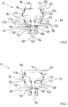
- FIG. 1 shows a circuit diagram of a preferred exemplary embodiment the pressure-operated vehicle brake system according to the invention with a switch valve arrangement.
- Fig. 2 shows the switch valve arrangement of Fig.1 in an enlarged view.
- Fig.3 shows in strong schematically shows a sectional view of a further changeover valve arrangement in a braking position and Fig.4 the switch valve arrangement of Figure 3 in an emergency braking position.
- Vehicle brake system is according to the preferred embodiment an electronically controlled braking system for commercial vehicles with priority electro-pneumatic brake circuits and with subordinate pneumatic restraint circuits as an underlying safety level.
- the front axle brakes are in the electronically controlled brake system 1 by a brake cylinder 2 of the left front wheel and represents a brake cylinder 4 of the right front wheel, which are each controlled by a single-channel pressure control module 6, 8.
- the pressure control modules 6, 8 of the front axle are on the one hand with their Pressure inputs 9 via a supply pressure line 10 with a compressed air reservoir 12 for the front axle and on the other hand with a control pressure line 14 with the control side of a front axle channel 16 one Service brake valve 18 connected.
- the front axle channel 16 of the service brake valve 18 is on the input side through a branch 20 of the supply pressure line 10 with the Compressed air reservoir 12 of the front axle in connection to depending the force with which the driver operates the brake pedal, proportional control pressure signals in the control pressure line 14 of the Front axle control.
- an electrical Part 22 of the service brake valve 18 is a proportional electric Control signal generated and via an electrical line 24 to a central electronic control unit 26, which each by means of electrical control line 28 a pressure control module 6, 8 of the front axle controls.
- a modulated control pressure is generated and via pneumatic Brake pressure lines 30 inserted into the brake cylinders 2, 4.
- the Compressed air reservoir 12 for the front axle, the electrical part 22 of the Service brake valve 18, the central electronic control unit 26, the electrical control lines 28, the two pressure control modules 6, 8, the brake pressure lines 30 and the brake cylinders 2, 4 form together an electro-pneumatic front axle brake circuit.
- the circuit logic of the pressure control modules 6, 8 deals with the electrical control signals of the electro-pneumatic front axle brake circuit primarily over those controlled via the control pressure line 14 Control pressure signals of a pneumatic front axle brake circuit, which is a redundant brake circuit Control functions when the electro-pneumatic front axle brake circuit is disturbed.
- the electro-pneumatic front axle brake circuit partially overlaps with pneumatic front axle brake circuit, the compressed air reservoir 12 for the front axle, the front axle channel 16 of the service brake valve 18, the control pressure line 14, the two pressure control modules 6, 8, the brake pressure lines 30 and the two brake cylinders 2, 4 comprises.
- ABS anti-lock braking system
- An electro-pneumatic rear axle brake circuit is analogous and a subordinate pneumatic one Rear axle brake circuit built, with a separate one for the rear axle Compressed air reservoir 36 is provided, which is through a supply pressure line 38 on the one hand with the entrance of a rear axle channel 40 of the service brake valve 18 and on the other hand with a two-channel Pressure control module 42 of the rear axle is connected, one each Channel is provided for a rear wheel.
- the service brake valve 18 controls on the one hand by means of a control pressure line 44 control pressure signals in the pressure control module 42 of the rear axle, which via pneumatic Brake pressure lines 46 with combination brake cylinders 48 of the right and left rear wheel is connected.
- those from Service brake valve 18 via the electrical line 24 to the central electronic control unit 26 controlled electrical signals by means of an electrical control line 50 into the pressure control module 42 the rear axle controlled.
- Control circuits depending on the pneumatic control pressure lines 14, 44 introduced control pressures are in the pressure control modules 6, 8, 42 of the front axle and the rear axle from the above the supply pressure lines 10, 38 brought up supply pressures in each case axially generated the brake pressures, each at a pressure outlet 52 of a pressure control module 6, 8, 42 are present and via the pneumatic brake pressure lines 30, 46 in the downstream Brake cylinder 2, 4 or combination brake cylinder 48 are controlled.
- the pressure output 52 of the left pressure control module 6 and the Brake cylinder 2 of the left front wheel is a changeover valve arrangement 54 interposed, which is outlined in dashed lines in FIG and is shown enlarged in Figure 2.
- the switch valve arrangement 54 preferably consists of a relay valve 56 and a this downstream 3/2-way valve 58, one as an actuating means 60 shown control chamber of the relay valve 56 by means of a pneumatic connecting line 62 with the control pressure line 44 of the pneumatic rear axle brake circuit in connection stands.
- a relay valve input 64 of the relay valve 56 is via a Supply pressure line 66 with a further compressed air reservoir 68 and a relay valve output 70 via a connecting line 72 with a first input 74 of the 3/2-way valve 58 connected.
- the 3/2-way valve 58 has a first control input 76 also to the pneumatic control pressure signals of the rear axle brake circuit leading connecting line 62 connected, it has a second control input 78 with one of the control pressure line 14 of the front axle branched pneumatic connecting line 80 connected.
- a second inlet 82 of the 3/2-way valve 58 is via a first part 84 of the brake pressure line 30 of the left front wheel with the pressure outlet 52 of the pressure control module 6 of the left front wheel and an outlet 86 of the 3/2-way valve 58 with a second part 88 of this brake pressure line 30 connected to the brake cylinder 2 of the left front wheel.
- the switch valve arrangement according to that shown in Fig.1 Embodiment has one introduced via the service brake valve 18 Braking as follows:
- a control pressure p vA is present in the control pressure line 14 of the pneumatic front axle brake circuit and in the pneumatic connection line 80 branched off from this, which pressure is in the second control input 78 of FIG / 2-way valve 58 is controlled.
- the control pressure line 44 of the pneumatic rear axle brake circuit and the pneumatic connecting line 62 branched off from it are acted upon by a control pressure PHA which is present at the first control input 76 of the 3/2-way valve 58.
- the valve actuating member 90 of the 3/2-way valve 58 which is only symbolically shown in FIGS.
- 1 and 2 is therefore constantly loaded by the control pressure p VA on its one active surface and by the control pressure p HA on its other active surface.
- 1 and 2 show the 3/2-way valve 58 in its basic braking position, in which its second input 82 is switched through to its output 86.
- the brake pressure controlled by the pressure control module 6 assigned to the left front wheel is switched through by the 3/2-way valve to the brake cylinder 2 of the left front wheel.
- the first input 74 of the 3/2-way valve connected to the relay valve output 70 is blocked.
- the control pressure p VA of the pneumatic front-axle brake circuit drops.
- the valve actuating member 90 of the 3/2-way valve 58 is pushed by the higher control pressure p HA from the basic braking position shown into an emergency braking position in which the first input 74 of the 3/2-way Valve 58 is connected to its output 86 and therefore the pressure present at the relay valve output 70 is switched through to the brake cylinder 2 of the left front wheel.
- the second inlet 82 of the 3/2-way valve 58 is blocked. Since the relay valve 56 is controlled by the stepped control pressure P HA controlled by the service brake valve 18, the pressure derived from the further compressed air accumulator 68 and switched to the 3/2-way valve 58 via the relay valve 56 is correspondingly stepped. This stepped pressure, which is introduced into the brake cylinder 2 of the left front wheel, finally leads to a deceleration of the left front wheel.
- FIG. 3 and 4 show a further embodiment of a changeover valve arrangement 91 shown in a highly schematic manner, in which it is realized by a relay valve 92.
- the relay valve 92 has a valve housing 94 within which a relay piston 96 is arranged to be longitudinally movable to an inlet valve 98 and to operate an exhaust valve 100 existing double seat valve 102.
- the inlet valve 98 includes one arranged on the valve housing 94 outer valve seat 104, against which by means of a valve spring 106 is a valve disk 108 in the form of a perforated disk Valve body is biased.
- the relay piston 96 has an end Piston pin 110, the edge of which is in the form of an annular, inner valve seat 112 is formed, which together with the valve plate 108 forms the exhaust valve 100 of the double seat valve 102.
- a first control chamber 114 of the relay valve 92 is through a upper active surface 116 of the relay piston 96 and through the valve housing 94 limited.
- the piston pin 110 of the relay piston 96 is enclosed coaxially by a perforated disk-shaped partition 118 which is guided longitudinally on it. From the lower effective area 120 of the relay piston 96 and an upper active surface 122 of the Partition 118 becomes a second control chamber 124 and one lower effective surface 126 of the partition 118 and the bottom of the valve housing 94, a working chamber 128 is delimited.
- One as a ring chamber trained pressure medium input chamber 130 of the relay valve encloses the double seat valve 102.
- the longitudinal displaceability the partition 118 is to the working chamber 128 through a paragraph 132 limited on the valve housing 94 (Fig.4).
- Another paragraph 134 am Piston pin 110 of the relay piston 96 provides an upper stop for the partition 118.
- Gaskets 135 between the relay piston 96 or between the partition 118 and the valve housing 94 seal the individual valve chambers against each other.
- the switch valve assembly 91 replaces the dashed outline in Fig.1 drawn embodiment 54 and is as follows in the vehicle brake system 1 integrated:
- the first control chamber 114 is similar to that in FIG. 1 with the reference number 62 designated and by the control pressure line 44 of the pneumatic Pneumatic connecting line branched off rear axle brake circuit and the second control chamber 124 to that in FIG Reference numeral 80 designated and from the control pressure line 14 of the pneumatic front axle brake circuit branched pneumatic Connection line connected.
- a bottom vent port 138 of the relay valve 92 is connected to the pressure output 52 of the pressure control module 6 leading first part 84 of the brake pressure line 30 of the left front wheel connected.
- the pressure medium inlet chamber 130 is with the in Fig.1 with the reference number 66 designated supply pressure line further compressed air reservoir 68 connected.
- the working chamber 128 stands with the leading to the brake cylinder 2 of the left front wheel second part 88 of the brake pressure line 30 in connection.
Landscapes
- Engineering & Computer Science (AREA)
- Transportation (AREA)
- Mechanical Engineering (AREA)
- Physics & Mathematics (AREA)
- Fluid Mechanics (AREA)
- Braking Systems And Boosters (AREA)
- Valves And Accessory Devices For Braking Systems (AREA)
- Regulating Braking Force (AREA)
Abstract
Description
Claims (10)
- Druckmittelbetätigte Fahrzeugbremsanlage (1) mit wenigstens einem ersten Bremskreis und einem zweiten Bremskreis mit folgenden Merkmalen :a) Dem ersten Bremskreis ist wenigstens ein Bremszylinder (48) zugeordnet, der über eine erste Steuerventileinrichtung (42) in Abhängigkeit von einem dem ersten Bremskreis zugeordneten Steuersignal eines Mehrkreis-Bremswertgebers (18) mit einer Druckmittelquelle (36) für den ersten Bremskreis verbindbar ist,b) dem zweiten Bremskreis sind ein erster Bremszylinder (2) und ein zweiter Bremszylinder (4) zugeordnet, die über eine zweite Steuerventileinrichtung (6, 8) in Abhängigkeit von einem dem zweiten Bremskreis zugeordneten Steuersignal des Mehrkreis-Bremswertgebers (18) mit einer zweiten Druckmittelquelle (12) für den zweiten Bremskreis verbindbar sind,c) die zweite Steuerventileinrichtung (6, 8) weist einen mit der Druckmittelquelle (12) für den zweiten Bremskreis verbundenen Druckmitteleingang (9) und einen mit dem ersten Bremszylinder (2) verbundenen Druckmittelausgang (52) auf,d) dem Druckmittelausgang (52) der zweiten Steuerventileinrichtung (6, 8) und dem ersten Bremszylinder (2) des zweiten Bremskreises ist eine Umschalt-Ventilanordnung (54; 91) zwischengeordnet, von welcher ein Ventilbetätigungsorgan (90; 96) von dem dem ersten Bremskreis zugeordneten Steuersignal derart drucksteuerbar ist, daß der erste Bremszylinder (2) mit einer von der Druckmittelquelle (12) des zweiten Bremskreises unabhängigen Druckmittelquelle (68) verbindbar ist,
dadurch gekennzeichnet, daße) das dem zweiten Bremskreis zugeordnete Steuersignal am Ventilbetätigungsorgan (90; 96) der Umschalt-Ventilanordnung (54; 91) ständig ansteht. - Druckmittelbetätigte Fahrzeugbremsanlage nach Anspruch 1, dadurch gekennzeichnet, daß die Umschalt-Ventilanordnung (54) ein Relaisventil (56) und ein diesem nachgeschaltetes 3/2-Wege-Ventil (58) beinhaltet, wobei:a) Ein Relaisventil-Eingang (64) mit der von der Druckmittelquelle (12) des zweiten Bremskreises unabhängigen Druckmittelquelle (68), ein Relaisventil-Ausgang (70) mit einem ersten Eingang (74) des 3/2-Wege-Ventils (58) und ein Relaisventil-Betätigungsmittel (60) durch das dem ersten Bremskreis zugeordnete Steuersignal betätigbar ist;b) ein zweiter Eingang (82) des 3/2-Wege-Ventils (58) mit dem Druckmittelausgang (52) der zweiten Steuerventileinrichtung (6, 8) und ein Ausgang (86) des 3/2-Wege-Ventils (58) mit dem ersten Bremszylinder (2) des zweiten Bremskreises verbunden ist;c) das Ventilbetätigungsorgan (90) des 3/2-Wege-Ventils (58) einerseits durch das dem ersten Bremskreis zugeordnete Steuersignal und andererseits durch das dem zweiten Bremskreis zugeordnete Steuersignal betätigbar ist;d) bei gleichzeitigem Vorhandensein beider Steuersignale der zweite Eingang (82) des 3/2-Wege-Ventils (58) zu dessen Ausgang (86) durchgeschaltet ist und wobeie) bei Vorhandensein des dem ersten Bremskreis zugeordneten Steuersignals und bei Ausbleiben oder Fehlen des dem zweiten Bremskreis zugeordneten Steuersignals vom Relaisventil (56) in Abhängigkeit von dem dem ersten Bremskreis zugeordneten Steuersignal ein gestufter Bremsdruck an den ersten Eingang (74) des 3/2-Wege-Ventils (58) aussteuerbar und der erste Eingang (74) des 3/2-Wege-Ventils (58) zu dessen Ausgang durchschaltbar ist.
- Druckmittelbetätigte Fahrzeugbremsanlage nach Anspruch 1, dadurch gekennzeichnet, daß die Umschalt-Ventilanordnung (91) ein Relaisventil (92) mit einem Relaiskolben (96) zum Betätigen eines Doppelsitzventils (102) beinhaltet, wobei:
a) Mittels eines Auslaßventils (100) des Doppelsitzventils (102) ein mit dem Druckmittelausgang (52) der zweiten Steuerventileinrichtung (6, 8) in Verbindung stehender Entlüftungsanschluß (138) des Relaisventils (92) mit einer mit dem ersten Bremszylinder (2) des zweiten Bremskreises in Verbindungs stehenden Arbeitskammer (128) des Relaisventils (92) verbindbar ist, und b) mittels eines Einlaßventils (98) des Doppelsitzventils (102) die mit einer Druckmitteleingangskammer (130) des Relaisventils (92) in Verbindung stehende, von der Druckmittelquelle (12) des zweiten Bremskreises unabhängige Druckmittelquelle (68) mit der Arbeitskammer (128) verbindbar ist, und c) der Relaiskolben (96) durch das dem ersten Bremskreis zugeordnete Steuersignal in eine das Einlaßventil (98) öffnende und das Auslaßventil (100) schließende Stellung und durch das dem zweiten Bremskreis zugeordnete Steuersignal in eine das Auslaßventil (100) öffnende und das Einlaßventil (98) schließende Stellung drängbar ist. - Druckmittelbetätigte Fahrzeugbremsanlage nach einem der Ansprüch 2 oder 3, dadurch gekennzeichnet, daß das dem ersten Bremskreis zugeordnete Steuersignal ein erster pneumatischer Steuerdruck ist , welcher über eine erste Steuerdruckleitung (44) in die erste Steuerventileinrichtung (42) einsteuerbar ist, und daß das dem zweiten Bremskreis zugeordnete Steuersignal ein zweiter pneumatischer Steuerdruck ist, welcher über eine zweite Steuerdruckleitung (14) in die zweite Steuerventileinrichtung (6, 8) einsteuerbar ist.
- Druckmittelbetätigte Fahrzeugbremsanlage nach Anspruch 4, dadurch gekennzeichnet, daß von der ersten Steuerdruckleitung (44) und von der
zweiten Steuerdruckleitung (14) jeweils eine pneumatische Verbindungsleitung (62, 80) zur Umschalt-Ventilanordnung (54; 91) abzweigt. - Druckmittelbetätigte Fahrzeugbremsanlage nach Anspruch 4 und 5, dadurch gekennzeichnet, daß zwischen einem Ventilgehäuse (94) des Relaisventils und (92) einer Wirkfläche (116) des Relaiskolbens (96) eine erste Steuerkammer (114) und zwischen einer anderen Wirkfläche (120) des Relaiskolbens (96) und einer entlang dem Relaiskolben (96) längsverschieblich geführten Trennwand (118) eine zweite Steuerkammer (124) und zwischen der Trennwand (118) und dem Ventilgehäuse (94) die Arbeitskammer (128) gebildet ist, wobei das Relaisventil (92) derart ausgebildet ist, daß bei gleichzeitiger Druckbeaufschlagung der ersten Steuerkammer (114) mit dem ersten Steuerdruck und der zweiten Steuerkammer (124) mit dem zweiten Steuerdruck das Einlaßventil (98) geschlossen und das Auslaßventil (100) geöffnet ist und daß bei Druckbeaufschlagung der ersten Steuerkammer (114) mit dem ersten Steuerdruck und einem Fehlen des zweiten Steuerdrucks in der zweiten Steuerkammer (124) das Auslaßventil (100) geschlossen und das Einlaß-ventil (98) geöffnet ist.
- Druckmittelbetätigte Fahrzeugbremsanlage nach einem der vorhergehenden Ansprüche, dadurch gekennzeichnet, daß sie ein elektronisch geregeltes Bremssystem beinhaltet, wobei bei Betätigung des Mehrkreis-Bremswertgebers (18) ein proportionales elektrisches Signal für eine zentrale elektronische Steuereinheit (26) erzeugbar ist, durch welche die erste und die zweite Steuerventilanordnung (6, 8, 42) vorrangig ansteuerbar sind.
- Druckmittelbetätigte Fahrzeugbremsanlage nach einem der vorhergehenden Ansprüche, dadurch gekennzeichnet, daß die erste Steuerventileinrichtung einen Zwei-Kanal-Druckregelmodul (42) beinhaltet, welcher mit der ersten Steuerdruckleitung (44) und mit der zentralen elektronischen Steuereinheit (26) ansteuerbar verbunden ist, wobei je ein Kanal einem Bremszylinder (48) des ersten Bremskreises zugeordnet ist.
- Druckmittelbetätigte Fahrzeugbremsanlage nach einem der Ansprüche 7 oder 8, dadurch gekennzeichnet, daß die zweite Steuerventileinrichtung zwei Ein-Kanal-Druckregelmodule (6, 8) beinhaltet, welche mit der zweiten Steuerdruckleitung (14) und mit der zentralen elektronischen Steuereinheit (26) ansteuerbar verbunden sind, wobei je ein Druckregelmodul (6, 8) einem Bremszylinder (2, 4) des zweiten Bremskreises zugeordnet ist.
- Druckmittelbetätigte Fahrzeugbremsanlage nach einem der vorhergehenden Ansprüche, dadurch gekennzeichnet, daß die erste Steuerventileinrichtung (42) mittels einer ersten Druckmittelleitung (38) mit der dem ersten Bremskreis zugeordneten Druckmittelquelle (36) und die zweite Steuerventileinrichtung (6, 8) mittels einer zweiten Druckmittelleitung (10) mit der dem zweiten Bremskreis zugeordneten Druckmittelquelle (12) verbunden ist.
Applications Claiming Priority (2)
| Application Number | Priority Date | Filing Date | Title |
|---|---|---|---|
| DE19954568A DE19954568A1 (de) | 1999-11-12 | 1999-11-12 | Druckmittelbetätigte Fahrzeugbremsanlage |
| DE19954568 | 1999-11-12 |
Publications (3)
| Publication Number | Publication Date |
|---|---|
| EP1099611A2 true EP1099611A2 (de) | 2001-05-16 |
| EP1099611A3 EP1099611A3 (de) | 2003-07-30 |
| EP1099611B1 EP1099611B1 (de) | 2004-12-01 |
Family
ID=7928878
Family Applications (1)
| Application Number | Title | Priority Date | Filing Date |
|---|---|---|---|
| EP00122298A Expired - Lifetime EP1099611B1 (de) | 1999-11-12 | 2000-10-20 | Druckmittelbetätigte Fahrzeugbremsanlage |
Country Status (3)
| Country | Link |
|---|---|
| EP (1) | EP1099611B1 (de) |
| AT (1) | ATE283782T1 (de) |
| DE (2) | DE19954568A1 (de) |
Cited By (3)
| Publication number | Priority date | Publication date | Assignee | Title |
|---|---|---|---|---|
| WO2018041385A1 (de) * | 2016-08-31 | 2018-03-08 | Wabco Gmbh | Elektronisch steuerbares pneumatisches bremssystem in einem nutzfahrzeug sowie verfahren zum elektronischen steuern eines pneumatischen bremssystems in einem nutzfahrzeug |
| CN116588060A (zh) * | 2023-05-31 | 2023-08-15 | 东风商用车有限公司 | 一种制动力调节控制装置、方法及车辆 |
| WO2024235658A1 (de) * | 2023-05-12 | 2024-11-21 | Daimler Truck AG | Druckluft-bremsvorrichtung und kraftfahrzeug mit einer solchen druckluft-bremsvorrichtung |
Families Citing this family (3)
| Publication number | Priority date | Publication date | Assignee | Title |
|---|---|---|---|---|
| DE102009009811A1 (de) * | 2009-02-20 | 2010-09-02 | Knorr-Bremse Systeme für Nutzfahrzeuge GmbH | Elektro-pneumatisches Druckregelmodul mit pneumatisch kreisgetrennten Druckregelkanälen |
| DE102016114831A1 (de) * | 2016-08-10 | 2018-02-15 | Knorr-Bremse Systeme für Nutzfahrzeuge GmbH | Mehrfachrelaisventil sowie pneumatisches Bremssystem mit wenigstens einem Mehrfachrelaisventil |
| DE102019116086A1 (de) * | 2019-06-13 | 2020-12-17 | WABCO Global GmbH | Einrichtung und Verfahren zur Abbremsung eines Fahrzeugs mit einer Frontlastaufnahmevorrichtung |
Citations (1)
| Publication number | Priority date | Publication date | Assignee | Title |
|---|---|---|---|---|
| EP0726190B1 (de) | 1995-02-10 | 1998-07-29 | WABCO GmbH | Druckmittelbetätigte Fahrzeugbremsanlage |
Family Cites Families (3)
| Publication number | Priority date | Publication date | Assignee | Title |
|---|---|---|---|---|
| DE3501179A1 (de) * | 1985-01-16 | 1986-07-17 | Wabco Westinghouse Fahrzeugbremsen GmbH, 3000 Hannover | Elektrische bremsanlage |
| DE19504394C1 (de) * | 1995-02-10 | 1996-03-07 | Wabco Gmbh | Druckmittelbetätigte Fahrzeugbremsanlage |
| DE19514603C2 (de) * | 1995-04-20 | 1997-04-03 | Daimler Benz Ag | Druckluft-Bremsanlage für ein Nutzfahrzeug |
-
1999
- 1999-11-12 DE DE19954568A patent/DE19954568A1/de not_active Withdrawn
-
2000
- 2000-10-20 DE DE50008823T patent/DE50008823D1/de not_active Expired - Lifetime
- 2000-10-20 EP EP00122298A patent/EP1099611B1/de not_active Expired - Lifetime
- 2000-10-20 AT AT00122298T patent/ATE283782T1/de not_active IP Right Cessation
Patent Citations (1)
| Publication number | Priority date | Publication date | Assignee | Title |
|---|---|---|---|---|
| EP0726190B1 (de) | 1995-02-10 | 1998-07-29 | WABCO GmbH | Druckmittelbetätigte Fahrzeugbremsanlage |
Cited By (6)
| Publication number | Priority date | Publication date | Assignee | Title |
|---|---|---|---|---|
| WO2018041385A1 (de) * | 2016-08-31 | 2018-03-08 | Wabco Gmbh | Elektronisch steuerbares pneumatisches bremssystem in einem nutzfahrzeug sowie verfahren zum elektronischen steuern eines pneumatischen bremssystems in einem nutzfahrzeug |
| JP2019524543A (ja) * | 2016-08-31 | 2019-09-05 | ヴァブコ・ヨーロッパ・ベスローテン・フェンノートシャップ・メット・ベペルクテ・アーンスプラーケレクヘイト | 商用車の電子制御可能な空気圧式制動システムと商用車の空気圧式制動システムの電子制御方法 |
| US11034341B2 (en) | 2016-08-31 | 2021-06-15 | Zf Cv Systems Europe Bv | Electronically controllable pneumatic brake system in a utility vehicle and method for electronically controlling a pneumatic brake system in a utility vehicle |
| CN109562754B (zh) * | 2016-08-31 | 2021-12-03 | 威伯科欧洲有限责任公司 | 气动制动系统、用于电子控制气动制动系统的方法及车辆 |
| WO2024235658A1 (de) * | 2023-05-12 | 2024-11-21 | Daimler Truck AG | Druckluft-bremsvorrichtung und kraftfahrzeug mit einer solchen druckluft-bremsvorrichtung |
| CN116588060A (zh) * | 2023-05-31 | 2023-08-15 | 东风商用车有限公司 | 一种制动力调节控制装置、方法及车辆 |
Also Published As
| Publication number | Publication date |
|---|---|
| EP1099611B1 (de) | 2004-12-01 |
| DE19954568A1 (de) | 2001-05-17 |
| ATE283782T1 (de) | 2004-12-15 |
| DE50008823D1 (de) | 2005-01-05 |
| EP1099611A3 (de) | 2003-07-30 |
Similar Documents
| Publication | Publication Date | Title |
|---|---|---|
| EP2707260B1 (de) | Parkbremseinrichtung | |
| EP0883538B1 (de) | Anhängersteuerventil für eine druckluftbremsanlage für kraftfahrzeuge | |
| EP2055542B1 (de) | Druckmittelbetätigte Bremseinrichtung eines Zugfahrzeugs mit einem gegenläufige Drücke für Anhängerbremsen erzeugenden Festellbremsmodul | |
| EP3414138B1 (de) | Relaisventileinrichtung einer pneumatischen oder elektro-pneumatischen kraftfahrzeugbremseinrichtung | |
| DE19918070B4 (de) | Druckregelvorrichtung für elektro-pneumatische Bremsanlagen von Fahrzeugen, insbesondere Nutzfahrzeugen | |
| EP3183145A1 (de) | Verfahren zum steuern einer durch eine betriebsbremsventileinrichtung betätigten betriebsbremseinrichtung sowie betriebsbremseinrichtung | |
| EP0399162A2 (de) | Bremskreis | |
| DE19923455C2 (de) | Druckmittelbetätigte Fahrzeugbremsanlage | |
| EP1069015B1 (de) | Druckmittelbetätigte Fahrzeugbremsanlage | |
| DE19935979C2 (de) | Druckmittelbetätigte Fahrzeugbremsanlage | |
| EP3277551B1 (de) | Drucklufteinrichtung für fahrzeuge mit doppelrelaisventil | |
| EP0726189B1 (de) | Druckmittelbetätigte Fahrzeugbremsanlage | |
| EP1099611B1 (de) | Druckmittelbetätigte Fahrzeugbremsanlage | |
| DE19932470B4 (de) | Druckmittelbetätigte Fahrzeugbremsanlage | |
| DE10042215C5 (de) | Druckmittelbetätigte Fahrzeugbremsanlage mit redundanter Ansteuerung wenigstens eines Bremszylinders | |
| EP1069016B2 (de) | Druckmittelbetätigte Fahrzeugbremsanlage | |
| DE10158065B4 (de) | Redundanzdruck-Umschaltventil für elektronisch-pneumatische Bremsanlage | |
| DE10139757A1 (de) | Anhängerbremsventil für Anhängefahrzeuge mit elektronischer Bremsregelung und erweiterter Sicherheit des geparkten Anhängers | |
| DE10139748A1 (de) | Anhängerbremsventil für einen Anhänger mit elektronischer Bremsregelung | |
| EP1188635B1 (de) | Anhängerbremsventil für einen Anhänger mit elektronischer Bremsregelung | |
| DE102010018614B3 (de) | Steuereinheit zum Erzeugen eines einen Fahrzustand eines Fahrzeugs kennzeichnenden Drucksignals | |
| DE3431674A1 (de) | Anhaengersteuerventil | |
| WO2025214683A1 (de) | Bistabiles elektropneumatisches anhängersteuermodul | |
| DE4408229A1 (de) | Zweikreis-Bremsventil für Druckluft-Bremsanlagen von Kraftfahrzeugen |
Legal Events
| Date | Code | Title | Description |
|---|---|---|---|
| PUAI | Public reference made under article 153(3) epc to a published international application that has entered the european phase |
Free format text: ORIGINAL CODE: 0009012 |
|
| AK | Designated contracting states |
Kind code of ref document: A2 Designated state(s): AT BE CH CY DE DK ES FI FR GB GR IE IT LI LU MC NL PT SE |
|
| AX | Request for extension of the european patent |
Free format text: AL;LT;LV;MK;RO;SI |
|
| PUAL | Search report despatched |
Free format text: ORIGINAL CODE: 0009013 |
|
| AK | Designated contracting states |
Designated state(s): AT BE CH CY DE DK ES FI FR GB GR IE IT LI LU MC NL PT SE |
|
| AX | Request for extension of the european patent |
Extension state: AL LT LV MK RO SI |
|
| 17P | Request for examination filed |
Effective date: 20040130 |
|
| GRAP | Despatch of communication of intention to grant a patent |
Free format text: ORIGINAL CODE: EPIDOSNIGR1 |
|
| AKX | Designation fees paid |
Designated state(s): AT BE CH CY DE DK ES FI FR GB GR IE IT LI LU MC NL PT SE |
|
| GRAS | Grant fee paid |
Free format text: ORIGINAL CODE: EPIDOSNIGR3 |
|
| GRAA | (expected) grant |
Free format text: ORIGINAL CODE: 0009210 |
|
| AK | Designated contracting states |
Kind code of ref document: B1 Designated state(s): AT BE CH CY DE DK ES FI FR GB GR IE IT LI LU MC NL PT SE |
|
| PG25 | Lapsed in a contracting state [announced via postgrant information from national office to epo] |
Ref country code: IT Free format text: LAPSE BECAUSE OF FAILURE TO SUBMIT A TRANSLATION OF THE DESCRIPTION OR TO PAY THE FEE WITHIN THE PRE;WARNING: LAPSES OF ITALIAN PATENTS WITH EFFECTIVE DATE BEFORE 2007 MAY HAVE OCCURRED AT ANY TIME BEFORE 2007. THE CORRECT EFFECTIVE DATE MAY BE DIFFERENT FROM THE ONE RECORDED.SCRIBED TIME-LIMIT Effective date: 20041201 Ref country code: FI Free format text: LAPSE BECAUSE OF FAILURE TO SUBMIT A TRANSLATION OF THE DESCRIPTION OR TO PAY THE FEE WITHIN THE PRESCRIBED TIME-LIMIT Effective date: 20041201 Ref country code: IE Free format text: LAPSE BECAUSE OF FAILURE TO SUBMIT A TRANSLATION OF THE DESCRIPTION OR TO PAY THE FEE WITHIN THE PRESCRIBED TIME-LIMIT Effective date: 20041201 Ref country code: FR Free format text: LAPSE BECAUSE OF NON-PAYMENT OF DUE FEES Effective date: 20041201 Ref country code: GB Free format text: LAPSE BECAUSE OF FAILURE TO SUBMIT A TRANSLATION OF THE DESCRIPTION OR TO PAY THE FEE WITHIN THE PRESCRIBED TIME-LIMIT Effective date: 20041201 |
|
| REG | Reference to a national code |
Ref country code: GB Ref legal event code: FG4D Free format text: NOT ENGLISH |
|
| REG | Reference to a national code |
Ref country code: CH Ref legal event code: EP |
|
| REG | Reference to a national code |
Ref country code: IE Ref legal event code: FG4D Free format text: GERMAN |
|
| REF | Corresponds to: |
Ref document number: 50008823 Country of ref document: DE Date of ref document: 20050105 Kind code of ref document: P |
|
| REG | Reference to a national code |
Ref country code: SE Ref legal event code: TRGR |
|
| PG25 | Lapsed in a contracting state [announced via postgrant information from national office to epo] |
Ref country code: GR Free format text: LAPSE BECAUSE OF FAILURE TO SUBMIT A TRANSLATION OF THE DESCRIPTION OR TO PAY THE FEE WITHIN THE PRESCRIBED TIME-LIMIT Effective date: 20050301 Ref country code: DK Free format text: LAPSE BECAUSE OF FAILURE TO SUBMIT A TRANSLATION OF THE DESCRIPTION OR TO PAY THE FEE WITHIN THE PRESCRIBED TIME-LIMIT Effective date: 20050301 |
|
| PG25 | Lapsed in a contracting state [announced via postgrant information from national office to epo] |
Ref country code: ES Free format text: LAPSE BECAUSE OF FAILURE TO SUBMIT A TRANSLATION OF THE DESCRIPTION OR TO PAY THE FEE WITHIN THE PRESCRIBED TIME-LIMIT Effective date: 20050312 |
|
| GBV | Gb: ep patent (uk) treated as always having been void in accordance with gb section 77(7)/1977 [no translation filed] |
Effective date: 20041201 |
|
| REG | Reference to a national code |
Ref country code: IE Ref legal event code: FD4D |
|
| PLBE | No opposition filed within time limit |
Free format text: ORIGINAL CODE: 0009261 |
|
| STAA | Information on the status of an ep patent application or granted ep patent |
Free format text: STATUS: NO OPPOSITION FILED WITHIN TIME LIMIT |
|
| PG25 | Lapsed in a contracting state [announced via postgrant information from national office to epo] |
Ref country code: AT Free format text: LAPSE BECAUSE OF NON-PAYMENT OF DUE FEES Effective date: 20051020 Ref country code: CY Free format text: LAPSE BECAUSE OF FAILURE TO SUBMIT A TRANSLATION OF THE DESCRIPTION OR TO PAY THE FEE WITHIN THE PRESCRIBED TIME-LIMIT Effective date: 20051020 |
|
| PG25 | Lapsed in a contracting state [announced via postgrant information from national office to epo] |
Ref country code: LU Free format text: LAPSE BECAUSE OF NON-PAYMENT OF DUE FEES Effective date: 20051031 Ref country code: CH Free format text: LAPSE BECAUSE OF NON-PAYMENT OF DUE FEES Effective date: 20051031 Ref country code: BE Free format text: LAPSE BECAUSE OF NON-PAYMENT OF DUE FEES Effective date: 20051031 Ref country code: MC Free format text: LAPSE BECAUSE OF NON-PAYMENT OF DUE FEES Effective date: 20051031 Ref country code: LI Free format text: LAPSE BECAUSE OF NON-PAYMENT OF DUE FEES Effective date: 20051031 |
|
| 26N | No opposition filed |
Effective date: 20050902 |
|
| EN | Fr: translation not filed | ||
| REG | Reference to a national code |
Ref country code: CH Ref legal event code: PL |
|
| BERE | Be: lapsed |
Owner name: *KNORR-BREMSE SYSTEME FUR NUTZFAHRZEUGE G.M.B.H. Effective date: 20051031 |
|
| PG25 | Lapsed in a contracting state [announced via postgrant information from national office to epo] |
Ref country code: PT Free format text: LAPSE BECAUSE OF NON-PAYMENT OF DUE FEES Effective date: 20050501 |
|
| PGFP | Annual fee paid to national office [announced via postgrant information from national office to epo] |
Ref country code: NL Payment date: 20081023 Year of fee payment: 9 |
|
| REG | Reference to a national code |
Ref country code: NL Ref legal event code: V1 Effective date: 20100501 |
|
| PG25 | Lapsed in a contracting state [announced via postgrant information from national office to epo] |
Ref country code: NL Free format text: LAPSE BECAUSE OF NON-PAYMENT OF DUE FEES Effective date: 20100501 |
|
| PGFP | Annual fee paid to national office [announced via postgrant information from national office to epo] |
Ref country code: DE Payment date: 20141024 Year of fee payment: 15 |
|
| REG | Reference to a national code |
Ref country code: DE Ref legal event code: R119 Ref document number: 50008823 Country of ref document: DE |
|
| PG25 | Lapsed in a contracting state [announced via postgrant information from national office to epo] |
Ref country code: DE Free format text: LAPSE BECAUSE OF NON-PAYMENT OF DUE FEES Effective date: 20160503 |
|
| PGFP | Annual fee paid to national office [announced via postgrant information from national office to epo] |
Ref country code: SE Payment date: 20181025 Year of fee payment: 19 |
|
| PG25 | Lapsed in a contracting state [announced via postgrant information from national office to epo] |
Ref country code: SE Free format text: LAPSE BECAUSE OF NON-PAYMENT OF DUE FEES Effective date: 20191021 |