EP1099534A2 - Three-dimensional printing techniques - Google Patents
Three-dimensional printing techniques Download PDFInfo
- Publication number
- EP1099534A2 EP1099534A2 EP00204516A EP00204516A EP1099534A2 EP 1099534 A2 EP1099534 A2 EP 1099534A2 EP 00204516 A EP00204516 A EP 00204516A EP 00204516 A EP00204516 A EP 00204516A EP 1099534 A2 EP1099534 A2 EP 1099534A2
- Authority
- EP
- European Patent Office
- Prior art keywords
- powder
- layer
- powder material
- binder
- component
- Prior art date
- Legal status (The legal status is an assumption and is not a legal conclusion. Google has not performed a legal analysis and makes no representation as to the accuracy of the status listed.)
- Withdrawn
Links
Images


Classifications
-
- H—ELECTRICITY
- H05—ELECTRIC TECHNIQUES NOT OTHERWISE PROVIDED FOR
- H05K—PRINTED CIRCUITS; CASINGS OR CONSTRUCTIONAL DETAILS OF ELECTRIC APPARATUS; MANUFACTURE OF ASSEMBLAGES OF ELECTRICAL COMPONENTS
- H05K3/00—Apparatus or processes for manufacturing printed circuits
- H05K3/10—Apparatus or processes for manufacturing printed circuits in which conductive material is applied to the insulating support in such a manner as to form the desired conductive pattern
- H05K3/102—Apparatus or processes for manufacturing printed circuits in which conductive material is applied to the insulating support in such a manner as to form the desired conductive pattern by bonding of conductive powder, i.e. metallic powder
-
- B—PERFORMING OPERATIONS; TRANSPORTING
- B05—SPRAYING OR ATOMISING IN GENERAL; APPLYING FLUENT MATERIALS TO SURFACES, IN GENERAL
- B05C—APPARATUS FOR APPLYING FLUENT MATERIALS TO SURFACES, IN GENERAL
- B05C19/00—Apparatus specially adapted for applying particulate materials to surfaces
- B05C19/04—Apparatus specially adapted for applying particulate materials to surfaces the particulate material being projected, poured or allowed to flow onto the surface of the work
-
- B—PERFORMING OPERATIONS; TRANSPORTING
- B22—CASTING; POWDER METALLURGY
- B22F—WORKING METALLIC POWDER; MANUFACTURE OF ARTICLES FROM METALLIC POWDER; MAKING METALLIC POWDER; APPARATUS OR DEVICES SPECIALLY ADAPTED FOR METALLIC POWDER
- B22F10/00—Additive manufacturing of workpieces or articles from metallic powder
- B22F10/10—Formation of a green body
- B22F10/14—Formation of a green body by jetting of binder onto a bed of metal powder
-
- B—PERFORMING OPERATIONS; TRANSPORTING
- B22—CASTING; POWDER METALLURGY
- B22F—WORKING METALLIC POWDER; MANUFACTURE OF ARTICLES FROM METALLIC POWDER; MAKING METALLIC POWDER; APPARATUS OR DEVICES SPECIALLY ADAPTED FOR METALLIC POWDER
- B22F10/00—Additive manufacturing of workpieces or articles from metallic powder
- B22F10/10—Formation of a green body
- B22F10/16—Formation of a green body by embedding the binder within the powder bed
-
- B—PERFORMING OPERATIONS; TRANSPORTING
- B22—CASTING; POWDER METALLURGY
- B22F—WORKING METALLIC POWDER; MANUFACTURE OF ARTICLES FROM METALLIC POWDER; MAKING METALLIC POWDER; APPARATUS OR DEVICES SPECIALLY ADAPTED FOR METALLIC POWDER
- B22F10/00—Additive manufacturing of workpieces or articles from metallic powder
- B22F10/60—Treatment of workpieces or articles after build-up
- B22F10/68—Cleaning or washing
-
- B—PERFORMING OPERATIONS; TRANSPORTING
- B22—CASTING; POWDER METALLURGY
- B22F—WORKING METALLIC POWDER; MANUFACTURE OF ARTICLES FROM METALLIC POWDER; MAKING METALLIC POWDER; APPARATUS OR DEVICES SPECIALLY ADAPTED FOR METALLIC POWDER
- B22F12/00—Apparatus or devices specially adapted for additive manufacturing; Auxiliary means for additive manufacturing; Combinations of additive manufacturing apparatus or devices with other processing apparatus or devices
- B22F12/50—Means for feeding of material, e.g. heads
- B22F12/57—Metering means
-
- B—PERFORMING OPERATIONS; TRANSPORTING
- B22—CASTING; POWDER METALLURGY
- B22F—WORKING METALLIC POWDER; MANUFACTURE OF ARTICLES FROM METALLIC POWDER; MAKING METALLIC POWDER; APPARATUS OR DEVICES SPECIALLY ADAPTED FOR METALLIC POWDER
- B22F3/00—Manufacture of workpieces or articles from metallic powder characterised by the manner of compacting or sintering; Apparatus specially adapted therefor ; Presses and furnaces
- B22F3/004—Filling molds with powder
-
- B—PERFORMING OPERATIONS; TRANSPORTING
- B28—WORKING CEMENT, CLAY, OR STONE
- B28B—SHAPING CLAY OR OTHER CERAMIC COMPOSITIONS; SHAPING SLAG; SHAPING MIXTURES CONTAINING CEMENTITIOUS MATERIAL, e.g. PLASTER
- B28B1/00—Producing shaped prefabricated articles from the material
- B28B1/001—Rapid manufacturing of 3D objects by additive depositing, agglomerating or laminating of material
-
- B—PERFORMING OPERATIONS; TRANSPORTING
- B29—WORKING OF PLASTICS; WORKING OF SUBSTANCES IN A PLASTIC STATE IN GENERAL
- B29C—SHAPING OR JOINING OF PLASTICS; SHAPING OF MATERIAL IN A PLASTIC STATE, NOT OTHERWISE PROVIDED FOR; AFTER-TREATMENT OF THE SHAPED PRODUCTS, e.g. REPAIRING
- B29C41/00—Shaping by coating a mould, core or other substrate, i.e. by depositing material and stripping-off the shaped article; Apparatus therefor
- B29C41/006—Shaping by coating a mould, core or other substrate, i.e. by depositing material and stripping-off the shaped article; Apparatus therefor using an electrostatic field for applying the material
-
- B—PERFORMING OPERATIONS; TRANSPORTING
- B29—WORKING OF PLASTICS; WORKING OF SUBSTANCES IN A PLASTIC STATE IN GENERAL
- B29C—SHAPING OR JOINING OF PLASTICS; SHAPING OF MATERIAL IN A PLASTIC STATE, NOT OTHERWISE PROVIDED FOR; AFTER-TREATMENT OF THE SHAPED PRODUCTS, e.g. REPAIRING
- B29C41/00—Shaping by coating a mould, core or other substrate, i.e. by depositing material and stripping-off the shaped article; Apparatus therefor
- B29C41/02—Shaping by coating a mould, core or other substrate, i.e. by depositing material and stripping-off the shaped article; Apparatus therefor for making articles of definite length, i.e. discrete articles
- B29C41/12—Spreading-out the material on a substrate, e.g. on the surface of a liquid
-
- B—PERFORMING OPERATIONS; TRANSPORTING
- B29—WORKING OF PLASTICS; WORKING OF SUBSTANCES IN A PLASTIC STATE IN GENERAL
- B29C—SHAPING OR JOINING OF PLASTICS; SHAPING OF MATERIAL IN A PLASTIC STATE, NOT OTHERWISE PROVIDED FOR; AFTER-TREATMENT OF THE SHAPED PRODUCTS, e.g. REPAIRING
- B29C41/00—Shaping by coating a mould, core or other substrate, i.e. by depositing material and stripping-off the shaped article; Apparatus therefor
- B29C41/34—Component parts, details or accessories; Auxiliary operations
- B29C41/36—Feeding the material on to the mould, core or other substrate
-
- B—PERFORMING OPERATIONS; TRANSPORTING
- B29—WORKING OF PLASTICS; WORKING OF SUBSTANCES IN A PLASTIC STATE IN GENERAL
- B29C—SHAPING OR JOINING OF PLASTICS; SHAPING OF MATERIAL IN A PLASTIC STATE, NOT OTHERWISE PROVIDED FOR; AFTER-TREATMENT OF THE SHAPED PRODUCTS, e.g. REPAIRING
- B29C64/00—Additive manufacturing, i.e. manufacturing of three-dimensional [3D] objects by additive deposition, additive agglomeration or additive layering, e.g. by 3D printing, stereolithography or selective laser sintering
- B29C64/10—Processes of additive manufacturing
- B29C64/165—Processes of additive manufacturing using a combination of solid and fluid materials, e.g. a powder selectively bound by a liquid binder, catalyst, inhibitor or energy absorber
-
- B—PERFORMING OPERATIONS; TRANSPORTING
- B29—WORKING OF PLASTICS; WORKING OF SUBSTANCES IN A PLASTIC STATE IN GENERAL
- B29C—SHAPING OR JOINING OF PLASTICS; SHAPING OF MATERIAL IN A PLASTIC STATE, NOT OTHERWISE PROVIDED FOR; AFTER-TREATMENT OF THE SHAPED PRODUCTS, e.g. REPAIRING
- B29C67/00—Shaping techniques not covered by groups B29C39/00 - B29C65/00, B29C70/00 or B29C73/00
- B29C67/02—Moulding by agglomerating
- B29C67/04—Sintering
-
- B—PERFORMING OPERATIONS; TRANSPORTING
- B29—WORKING OF PLASTICS; WORKING OF SUBSTANCES IN A PLASTIC STATE IN GENERAL
- B29C—SHAPING OR JOINING OF PLASTICS; SHAPING OF MATERIAL IN A PLASTIC STATE, NOT OTHERWISE PROVIDED FOR; AFTER-TREATMENT OF THE SHAPED PRODUCTS, e.g. REPAIRING
- B29C67/00—Shaping techniques not covered by groups B29C39/00 - B29C65/00, B29C70/00 or B29C73/00
- B29C67/24—Shaping techniques not covered by groups B29C39/00 - B29C65/00, B29C70/00 or B29C73/00 characterised by the choice of material
- B29C67/242—Moulding mineral aggregates bonded with resin, e.g. resin concrete
- B29C67/243—Moulding mineral aggregates bonded with resin, e.g. resin concrete for making articles of definite length
-
- B—PERFORMING OPERATIONS; TRANSPORTING
- B33—ADDITIVE MANUFACTURING TECHNOLOGY
- B33Y—ADDITIVE MANUFACTURING, i.e. MANUFACTURING OF THREE-DIMENSIONAL [3D] OBJECTS BY ADDITIVE DEPOSITION, ADDITIVE AGGLOMERATION OR ADDITIVE LAYERING, e.g. BY 3D PRINTING, STEREOLITHOGRAPHY OR SELECTIVE LASER SINTERING
- B33Y10/00—Processes of additive manufacturing
-
- B—PERFORMING OPERATIONS; TRANSPORTING
- B33—ADDITIVE MANUFACTURING TECHNOLOGY
- B33Y—ADDITIVE MANUFACTURING, i.e. MANUFACTURING OF THREE-DIMENSIONAL [3D] OBJECTS BY ADDITIVE DEPOSITION, ADDITIVE AGGLOMERATION OR ADDITIVE LAYERING, e.g. BY 3D PRINTING, STEREOLITHOGRAPHY OR SELECTIVE LASER SINTERING
- B33Y30/00—Apparatus for additive manufacturing; Details thereof or accessories therefor
-
- B—PERFORMING OPERATIONS; TRANSPORTING
- B41—PRINTING; LINING MACHINES; TYPEWRITERS; STAMPS
- B41J—TYPEWRITERS; SELECTIVE PRINTING MECHANISMS, i.e. MECHANISMS PRINTING OTHERWISE THAN FROM A FORME; CORRECTION OF TYPOGRAPHICAL ERRORS
- B41J2/00—Typewriters or selective printing mechanisms characterised by the printing or marking process for which they are designed
- B41J2/005—Typewriters or selective printing mechanisms characterised by the printing or marking process for which they are designed characterised by bringing liquid or particles selectively into contact with a printing material
- B41J2/01—Ink jet
- B41J2/07—Ink jet characterised by jet control
- B41J2/075—Ink jet characterised by jet control for many-valued deflection
- B41J2/08—Ink jet characterised by jet control for many-valued deflection charge-control type
- B41J2/085—Charge means, e.g. electrodes
-
- B—PERFORMING OPERATIONS; TRANSPORTING
- B41—PRINTING; LINING MACHINES; TYPEWRITERS; STAMPS
- B41J—TYPEWRITERS; SELECTIVE PRINTING MECHANISMS, i.e. MECHANISMS PRINTING OTHERWISE THAN FROM A FORME; CORRECTION OF TYPOGRAPHICAL ERRORS
- B41J2/00—Typewriters or selective printing mechanisms characterised by the printing or marking process for which they are designed
- B41J2/005—Typewriters or selective printing mechanisms characterised by the printing or marking process for which they are designed characterised by bringing liquid or particles selectively into contact with a printing material
- B41J2/01—Ink jet
- B41J2/07—Ink jet characterised by jet control
- B41J2/075—Ink jet characterised by jet control for many-valued deflection
- B41J2/08—Ink jet characterised by jet control for many-valued deflection charge-control type
- B41J2/09—Deflection means
-
- B—PERFORMING OPERATIONS; TRANSPORTING
- B22—CASTING; POWDER METALLURGY
- B22F—WORKING METALLIC POWDER; MANUFACTURE OF ARTICLES FROM METALLIC POWDER; MAKING METALLIC POWDER; APPARATUS OR DEVICES SPECIALLY ADAPTED FOR METALLIC POWDER
- B22F12/00—Apparatus or devices specially adapted for additive manufacturing; Auxiliary means for additive manufacturing; Combinations of additive manufacturing apparatus or devices with other processing apparatus or devices
- B22F12/22—Driving means
- B22F12/226—Driving means for rotary motion
-
- B—PERFORMING OPERATIONS; TRANSPORTING
- B22—CASTING; POWDER METALLURGY
- B22F—WORKING METALLIC POWDER; MANUFACTURE OF ARTICLES FROM METALLIC POWDER; MAKING METALLIC POWDER; APPARATUS OR DEVICES SPECIALLY ADAPTED FOR METALLIC POWDER
- B22F12/00—Apparatus or devices specially adapted for additive manufacturing; Auxiliary means for additive manufacturing; Combinations of additive manufacturing apparatus or devices with other processing apparatus or devices
- B22F12/38—Housings, e.g. machine housings
-
- B—PERFORMING OPERATIONS; TRANSPORTING
- B22—CASTING; POWDER METALLURGY
- B22F—WORKING METALLIC POWDER; MANUFACTURE OF ARTICLES FROM METALLIC POWDER; MAKING METALLIC POWDER; APPARATUS OR DEVICES SPECIALLY ADAPTED FOR METALLIC POWDER
- B22F12/00—Apparatus or devices specially adapted for additive manufacturing; Auxiliary means for additive manufacturing; Combinations of additive manufacturing apparatus or devices with other processing apparatus or devices
- B22F12/60—Planarisation devices; Compression devices
- B22F12/63—Rollers
-
- B—PERFORMING OPERATIONS; TRANSPORTING
- B22—CASTING; POWDER METALLURGY
- B22F—WORKING METALLIC POWDER; MANUFACTURE OF ARTICLES FROM METALLIC POWDER; MAKING METALLIC POWDER; APPARATUS OR DEVICES SPECIALLY ADAPTED FOR METALLIC POWDER
- B22F12/00—Apparatus or devices specially adapted for additive manufacturing; Auxiliary means for additive manufacturing; Combinations of additive manufacturing apparatus or devices with other processing apparatus or devices
- B22F12/60—Planarisation devices; Compression devices
- B22F12/67—Blades
-
- B—PERFORMING OPERATIONS; TRANSPORTING
- B22—CASTING; POWDER METALLURGY
- B22F—WORKING METALLIC POWDER; MANUFACTURE OF ARTICLES FROM METALLIC POWDER; MAKING METALLIC POWDER; APPARATUS OR DEVICES SPECIALLY ADAPTED FOR METALLIC POWDER
- B22F2998/00—Supplementary information concerning processes or compositions relating to powder metallurgy
-
- G—PHYSICS
- G05—CONTROLLING; REGULATING
- G05B—CONTROL OR REGULATING SYSTEMS IN GENERAL; FUNCTIONAL ELEMENTS OF SUCH SYSTEMS; MONITORING OR TESTING ARRANGEMENTS FOR SUCH SYSTEMS OR ELEMENTS
- G05B2219/00—Program-control systems
- G05B2219/30—Nc systems
- G05B2219/49—Nc machine tool, till multiple
- G05B2219/49013—Deposit layers, cured by scanning laser, stereo lithography SLA, prototyping
-
- H—ELECTRICITY
- H05—ELECTRIC TECHNIQUES NOT OTHERWISE PROVIDED FOR
- H05K—PRINTED CIRCUITS; CASINGS OR CONSTRUCTIONAL DETAILS OF ELECTRIC APPARATUS; MANUFACTURE OF ASSEMBLAGES OF ELECTRICAL COMPONENTS
- H05K2203/00—Indexing scheme relating to apparatus or processes for manufacturing printed circuits covered by H05K3/00
- H05K2203/01—Tools for processing; Objects used during processing
- H05K2203/0104—Tools for processing; Objects used during processing for patterning or coating
- H05K2203/013—Inkjet printing, e.g. for printing insulating material or resist
-
- H—ELECTRICITY
- H05—ELECTRIC TECHNIQUES NOT OTHERWISE PROVIDED FOR
- H05K—PRINTED CIRCUITS; CASINGS OR CONSTRUCTIONAL DETAILS OF ELECTRIC APPARATUS; MANUFACTURE OF ASSEMBLAGES OF ELECTRICAL COMPONENTS
- H05K2203/00—Indexing scheme relating to apparatus or processes for manufacturing printed circuits covered by H05K3/00
- H05K2203/05—Patterning and lithography; Masks; Details of resist
- H05K2203/0502—Patterning and lithography
- H05K2203/0522—Using an adhesive pattern
Definitions
- This invention relates generally to the manufacture of tooling and prototype parts and, more particularly, to the use of three-dimensional printing techniques using computer models therefor.
- the solid layer is then lowered into the bath and the laser generated polymerization process is repeated for the generation of the next layer, and so on, until a plurality of superimposed layers forming the desired part is obtained.
- the most recently created layer in each case is always lowered to a position for the creation of the next layer slightly below the surface of the liquid bath.
- SLS Selective Laser Sintering
- LOM Laminated Object Manufacturing
- BPM Ballistic Particle Manufacturing
- An ink-jet printing technique wherein an ink-jet stream of liquid molten metal or a metal composite material is used to create three-dimensional objects under computer control, similar to the way an ink-jet printer produces two-dimensional graphic printing.
- a metal or metal composite part is produced by ink-jet printing of successive cross sections, one layer after another, to a target using acold welding (i.e., rapid solidification) technique, which causes bonding between the particles and the successive layers.
- Photochemical Machining proposed by Formigraphic Engine Co. of Berkeley, California, uses intersecting laser beams to selectively harden or soften a polymer plastic block. The underlying mechanism used is the photochemical cross-linking or degradation of the material.
- powdered material e.g., a powdered ceramic, a powdered metal, or a powdered plastic
- a liquid binder material is selectively supplied to the layer of powdered material using an ink-jet printing technique in accordance with a computer model of the three-dimensional part being formed.Following the sequential application of all of the required powder layers and binder material to form the part in question, the unbound powder is appropriately removed, resulting in the formation of the desired three-dimensional part. It is found that such technique permits complex metal, ceramic, or metal-ceramic composite parts to be effectively formed with a very high degree of resolution in a reasonably short time period.
- Such technique should be particularly useful, for example, in providing for the rapid production of molds for metal casting and the rapid formation of pre-forms for metal matrix composites. Such technique can also be used with plastic materials to form plastic components or parts for various purposes.
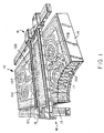
- FIG. 1 depicts an apparatus 10 for forming a ceramic mold having six cavities 12A-12F which can be used for casting six substantially identical parts.
- a powder dispersion head 13 is driven reciprocally in a shuttle motion along the length of themold being formed.
- a suitable linear stepping motor assembly 18 can be used for moving the powder distribution head 13 and the binder deposition head 15 (discussed below).
- the powdered material e.g., a ceramic powder
- a confined region e.g., defined by a form 14
- the powder being dispensed in a line as the dispensing head 13 is moved in discrete steps along the mold length to form a relatively loose layer thereof having a typical thickness of about 100-200 microns, for example.
- the material is described here as a powdered material, in some applications it can be distributed in the form of fibers, for example.
- the term powder material will be construed to include fiber material.
- the stepping motor can be moved at such high speeds that the motion of the head 13 will effectively be continuous in nature. Alternatively, the motor may be one which inherently provides a continuous motion, such as a servo-controlled motor.
- An initial layer is dispersed at the bottom of the form 14 and each subsequent layer is dispersed sequentially on the preceding layer.
- An ink-jet print head 15 having a plurality of ink-jet dispensers is also driven by the stepping motor assembly in the same reciprocal manner so as to follow the motion of the powder head and to selectively produce jets of a liquid binder material at selected regions 16 which represent the walls of each cavity, thereby causing the powdered material at such regions to become bonded.
- the binder jets are dispensed along a line of theprinthead 15 which is moved in substantially the same manner as the dispensing head 13 of the powder material, i.e., by a high speed stepping operation or by a continuous servo motor operation, in each case providing effectively continuous movement of head 15 as discussed above with reference to head 13.
- Typical binder droplet sizes are about 15-50 microns, for example.
- the powder/binder layer forming process is repeated so as to build up the mold parts layer by layer.
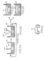
- FIG. 2 A diagram showing a part being fabricated in accordance with the invention is depicted in FIG. 2 which diagrammatically depicts the flow thereof.
- a layer of powder is deposited from a powder dispensing head 41 into a form 42 over a previously formed layer which has already had binder material deposited therein (A).
- a layer of binder material is then printed onto the powder layer from binding jet head 43 to form the next layer 44 of bonded powder articles (B). Such operation is repeated for each subsequent layer.
- An exemplary intermediate stage of the formation of part 40 is shown at (C).
- the final bonded layer is printed as shown at (D)
- excess, unbonded powder is removed, the finally formed part itself being depicted at (E).
- the form and its contents be heated or cured at a suitably selectedtemperature to futher promote binding of the powder particles.
- the loose, unbonded powder particles e.g., at regions 17 (FIG. 1), are removed using a suitable technique, such as ultrasonic cleaning, for example, so as to leave a finished part for use.
- the powder particles should be uniformly deposited at a relatively high rate, the rate being selected in accordance with the application for which the technique is used.
- the powder particles can preferably be packed at relatively high densities, while in other applications the density may be considerably lower where parts having greater porosity are desired.
- Known techniques used in the fields of colloidal science and powder dispersion chemistry can be used to provide the desired uniform depositions of such powders at the required rates and densities.
- such powders can be dispensed either as dry powders or in a liquid Vehicle, such as in a colloidal dispersant or in an aqueous suspension.
- the desired compaction of particles can be achieved using mechanical vibrating compaction techniques or by applying acoustic energy, i.e., either sonic or ultrasonic vibrations, to the deposited powder or by applying a piezoelectric scraper to the deposited powder.
- acoustic energy i.e., either sonic or ultrasonic vibrations
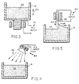
- FIG. 3 shows form 14 which is mechanically vibrated as shown by arrow 60 using a vibrating transducer system 61 for settling the powder particles 62 therein.
- an acoustic transducer system 63 is used to supply acoustic energy 64 to the surface layer of powder 62 for such purpose.
- a vibrating tranducer system 65 is used to vibrate a piezoelectric scraper 66 as shown by arrow 67 as it moves in the exemplary direction of arrow 68 to settle the powder 62.
- the powder may also be deposited in a dry or in a wet form using a drop piston approach wherein a dry or moist powder is deposited on the top of a vertically movable piston and the piston is moved downwardly into a chamber, excess powder being scraped off with a suitable scraper device.
- a piston 70 holds the part 71 shown as partially formed within a chamber 72 at diagram (A).
- the piston is moved downwardly in the chamber, leaving a region in chamber 73 at the top thereof for deposition of powder particles at diagram (B).
- Powder particles 74 are deposited in such region and a doctor blade 75, for example, is used to scrape off excess powder at diagram (c).
- the part 71 having the newly deposited layer 76 of powder thereon is then ready for the application of binder material thereto at diagram (D).
- a horizontal roller 101 is mounted for both rotation and vibration simultaneously.
- the end shafts of the roller 101 are mounted in bearings 103 and 105 which are in turn mounted on leaf springs inclined at an angle of about 45 degrees to the vertical.
- Roller 101 is driven in rotation by a suitable motor (not shown) and the entire roller system is vibrated by an electromagnetic driver designated generally by reference character 109.
- an electromagnetic driver designated generally by reference character 109.
- the roller is translated across the surface of the newly deposited layer so as to smooth and compact it.
- the vibration will thus have a component which is longitudinal to the roller and also a component which is vertical or normal to the powder layer and thus aids in densification or compaction of the powder.
- the rotation of the roller is counter to the direction of the translation so that excess powder is driven ahead of the roller during the spreading step.
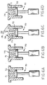
- Figs. 8A-8C Such a procedure is illustrated in Figs. 8A-8C.
- Fig. 8A newly deposited powder is spread across the top of the powder masswhich is confined within a cylinder 112 and supported by piston 113 using a roller 114 which is traversed across the printing region (from left to right as shown) and is rotated in a direction opposing the traversing (counterclockwise as shown) so as to drive excess powder ahead of the roller.
- Fig. 8C After spreading, the piston is raised by an amount corresponding to the degree of compaction desired as shown in Fig. 8B. Then the roller 114 is traversed back across the printing region which the direction of rotation corresponding to the traversing motion so that the newly spread powder layer is compacted as illustrated in Fig. 8C.
- An alternative to the rolling step of Fig. 8C would be to use a flat platen which is pressed down on the newly spread layer. 'As will be understood, deformation must be limited to the top layer only, since previously built portions of the part could be distorted by pressing. Fortunately, granulated systems transform from plastic to elastic behavior over a relatively narrow range in compaction density.
- deformation during compaction can be expected to be limited to the top layer if a minimum density is established during the build process.
- Many powder pressing operations use granulated powder to improve flowability.
- the granules are typically prepared by spray drying and are composed of fine particles and organic binder.
- the binder is heavily plasticized so that they deform easily upon pressing.
- Pressed bodies exhibitsurprisingly uniform packing density because the granules exhibit highly nonlinear mechanical -characteristics.
- the final body would be essentially a dry pressed component formed by lamination. Dry pressing is known to control particle packing well if the dimensions of the body are small in the direction that the load is applied.
- Removal of the printed component would be achieved by using a water soluble binder for the spray dried granules and a latex binder for the ink jet printing. Sonication of the laminated structure in water would then only remove the excess material since the dried latex will not redisperse in water.
- An alternative approach is to accomplish densification or compaction by spraying a small amount of liquid on the surface which allows the particles to repack during drying.
- An example is to spread alumina particles in the .5 - 5 micron range and then to spray or mist water onto the spread layer. The water will cause the particles to rearrange and repack, resulting in a high density layer. If a small amount of water is used, there will be no need to dry the layer before printing. If a larger amount of water is used, the layer may have to be partially dried before printing.
- doctor blade While spreading by means of a roller is appropriate in many situations, some materials are better spread with a doctor blade as mentioned previously.
- An improved form of doctor blade is illustrated in Figure 9.
- the doctor blade, designated by reference character 117, has a shape which can be best described as a snowplow configuration, that is, the surface facing the material to be spread is concave, terminating in an edge which contacts the printing region. Acocordingly, as the blade is traversed across the printing region, excess deposited powder is in effect cleaved from the powder mass and rolled ahead of the advancing blade.
- FIG. 10 An improved form of piston mechanism is illustrated in Fig. 10. While a piston guided by the cylinder walls is workable in many situations, the piston can be prone to jamming or sticking as powder particles enter the sliding interface between the piston and the cylinder. In the mechanism of Fig.10, a separate means is provided for aligning the piston within the cylinder and provides an appreciable gap between them.
- the cylinder is designated by reference character 120
- the plate which carries the powder bed, i.e. the piston is designated by reference character 121.
- the plate 121 is secured by means of a vacuum chuck 123 on one end of a plunger 125.
- the other end of the plunger is mounted on a carriage 127 which runs along a linear bearing 129.
- the linear bearing system provides precise location of the piston plate 121 within the cylinder 120 independently of any contact between those parts.
- Vertical movement of the piston is controlled by a linear actuator 130.
- the gap between the piston and the cylinder is filled by a fiber seal 131.
- the seal does not have to be an absolute one. If some powder leaks past the seal, no harm is done but, rather, it can be cleaned from the space below the piston after printing is completed. Escape of any powder from the piston area to the linear bearing and carriage is blocked by a bellows seal 133. In some instances, it may not be necessary to provide any compliant seal at all since the natural bridging tendency of the powder may be sufficient to prevent the escape of excessive quantities.
- a further advantage of this construction is that the piston plate 121 and cylinder 120 form a modular unit which, after the printing process, can be removed from the drive mechanism with the printed part in place in the powder bed. This modular unit can then be fired in the furnace and the component removed from the powder bed after firing. In this manner, a delicate part can be fired before it is disturbed. As will also be understood, multiple such modular units can be used so that one part can be printed while another part is beingfired.
- the need for providing a cylinder wall for the entire depth of the printed volume may be avoided by,, in effect, printing a confining wall member.
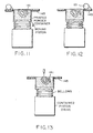
- a confining wall member Such a procedure is illustrated in Figs. 11-13.
- the printhead In addition to printing the part 141 which is to be formed, the printhead also prints a wall or container around the periphery of the powder bed. The printing of the peripheral wall is performed stepwise in the same manner as the printing of the part.
- the piston 143 is moved down an increment with respect to a stationary platen 145as illustrated in Fig. 11 and then a new layer of powder is spread over the bed as illustrated in Fig. 12.
- the spreading may, for example, be performed by the rotating and vibrating cylinder mechanism illustrated in Fig.
- the platen 145 includes an opening which loosely confines the just spread powder layer.
- a printing step is performed as illustrated in Fig. 13 during which the ink jet 151 deposits binder material, not only as required for forming of the part, but also for building up a peripheral wall 144 spaced slightly inwardly from the edge of the platen opening as illustrated.
- the newly printed peripheral wall portion serves to confine the powder bed below the opening in the platen.
- Figs. 11-13 assume that the powder bed is moved downward with respect to a fixed platen, it should be understood that essentially the same manner of producing a supporting peripheral wall can be utilized where the platen and associated powder spreading and printing mechanisms are moved upwards, i.e. with respect to a stationary base which supports the powder bed including its incrementally formed peripheral wall. This latter arrangement may be of particular utility where the part being formed is particularly massive and it is easier to raise the platen and printing components rather than lower the powder bed.
- peripheral wall member even though a cylinder is used to confine the powderduring printing.
- the peripheral wall member so formed can facilitate handling of the component after removal from the cylinder, e.g., prior to final heat treatment or sintering.
- FIG. 14 An improved mechanism for laying down the bead of powder which is then spread across the powder bed is illustrated in Fig. 14.
- the mechanism illustrated employs a powder dispensing head which is in the form of an inclined cylindrical housing and which can be traversed across one edge of the printing region with powder being dispensed through an outlet 163.
- a rotatable drum 165 Within the cylindrical housing 161 is a rotatable drum 165.
- the cylindrical wall of the drum 165 is constructed of a suitable screen or sieve material and the drum is journaled for rotation around its longitudinal axis.
- the lower end of the drum is preferably solid and closed off, as illustrated, while the upper end of the drum includes an opening 167 through which the material to be spread can be introduced into the interior of the drum.
- a suitable source reservoir is indicated generally by reference character 171, the reservoir being provided with a valve 173 which can be opened to introduce the material into the drum when the dispenser is at the end of its travel, i.e. the left hand end as illustrated.
- the amount dispensed along the line of powder being laid down can also be adjusted or profiled by varying the speed at which the dispensing head is traversed. For example, if it is found desirable to deposit more powder at the beginning and end of the line, this may be accomplished by moving the dispensing head more slowly in these areas.
- An alternative arrangement is to provide a sieve drum which is as long as the width of the print region and to traverse it with rotation across the printing area so as to lay down an essentially uniform layer.
- An elongate sieve drum designated generally by reference character 171 is mounted on a carriage (not shown) which allows the drum to be traversed and rotated across the printing area, i.e. over the top of a piston and cylinder mechanism 173, which may, for example, be of the typedescribed in greater detail with reference to Fig. 10.
- larger particles for example, of about 20 microns or greater in size
- smaller particles for example, of about 5 microns or smaller in size
- Colloidal dispersions of particles can be obtained in a liquid vehicle by the addition of chemical dispersants.
- the liquid used in a wet powder dispersion technique is removed, or partially removed, before the next layer is deposited.
- Such liquid is caused to evaporate rapidly before the ink-jet binder printing occurs.
- Such evaporation can be achieved, for example, by using infra-red heating, hot air heating or microwave heating techniques.
- the ink-jet printing of the binder material should utilize droplets of materials the shrink characteristics of which are selected so that the dimensional tolerances of the part being made are maintained upon hardening thereof. While the binder solution must have a relatively high binder content, the viscosity thereof should be low enough so as to be able to flow through the printing head for deposit into the powder material. The binder material should be selected to penetrate the layer and to perform its binding action relatively rapidly in each layer so that the next layer of powder particles can be subsequently applied thereto. When using certain ink-jet technology the binder material may require at least a minimumelectrical conductivity, particularly when using currently available continuous jet printing heads, for example, which require enough conductivity to establish charge on the binder solution droplets as they are emitted from the head. Where conductivity cannot be established in the binder, as withcertain organic solvents, for example, the binder can be applied using drop-on-demand print heads.
- the binder material may be such that the bonded particles have a high binding strength as each layer is deposited so that, when all the layers have been bonded, the component formed thereby is ready for use without further processing. In other cases, it may be desirable, or necessary, to perform further processing of the part. For example, while the process may be such as to impart a reasonable strength to the component which is formed, once the part is formed it can be further heated or cured to further enhance the binding strength of the particles.
- the binder in some cases can be removed during such heating or firing process, while in others it can remain in the material after firing. Which operation occurs depends on the particular binder material which has been selected for use and on the conditions, e.g., temperature, under which the heating or firing process is performed.
- the rate at which a ceramic, metal, plastic, or composite component can be made depends on the rates used to deposit the powder and to supply the binder liquid, and on the rate at which each bonded layer hardens as the layers are deposited one on the other.
- the powder application step is less significant as a limiting factor in determing the overall printing rate. If powder dispersion in aliquid vehicle is used, however, the layer must be at least partially dry prior to the ink-jet application of the binder material. The drying time will depend on the specific nature of the powder, binder, and solvent used.
- the dimensions of the individual portions of the component being formed is primarily dependent on the size of the binder droplets used, while the tolerance on such dimensions primarily depends on the degree of the reproducibility of the droplet spread characteristics of the binder material which is utilized.
- Ink-jet printing of a liquid binder using currently known ink-jet devices can provide jet droplet sizes of as low as 15 microns, for example. It is possible that even smaller droplet sizes will be practical, with the lower limit on droplet size arising from surface energy considerations in the creation of new surface area and in the increased likelihood of the clogging of small jets.
- Alumina, zirconia, zircon (i.e., zirconium silicate), and silicon carbide are representative ceramic materials which can be bonded using the techniques of the invention. Both natural and synthetic dispersants are available for these materials in organic vehicles.
- alumina is very effectively dispersed by glyceride surfactants in toluene/MEK solvents, as is used for casting thin sheets of particles in the production of dielectric substrates in the electronic packaging industry.
- Silicon carbide for example, can be easily dispersed in hexane if small amounts of OLOA 1200 (as obtained, for example, from Chevron Chemical Co. Oronite Additives Div. of San Francisco, California) are present.
- OLOA is primarily used as an additive in crank case oil where it acts as a dispersant for metal particles produced by engine wear.
- Organic binders have been used in the ceramics industry and are typically polymeric resins obtained from a variety of sources. They can be either water soluble, such as celluosic binders, as used in extrusion technology, or they can be soluble in only volatile organic solvents, such as the butyral resins, as used in tape casting technology. The latter water soluble systems can be removed relatively quickly and seem particularly useful in the technique of the invention.
- Another type of organic binder would be a ceramic precursor material such as polycarbosilazane. Inorganic binders are useful in cases where the binder is to be incorporated into the final component.
- Such binders are generally silicate based and are typically formed from the polymerization of silicic acid or its salts in aqueous solution.
- Another exemplary inorganic binder which can be used is TEOS (tetraethylorthosilicate).
- TEOS tetraethylorthosilicate
- the colloidal silica aggregates at the necks of the matrix particles to form a cement-like bond.
- the silica flows and acts to rearrange the matrix particles through the action of surface tension forces and remains after firing.
- Soluble silicate materials have been used as binders in refractory castable materials, for example, and have the advantage, when used in the technique of the invention, of producing substantially the same type of molded refractory body that is used in the casting industry.
- the binder harden relatively rapidly upon being deposited so that the next layer of particles placed on a surface of the previous layer is not subject to particle rearrangement due to capillary forces.
- a hardened binder is not subject to contamination from solvents which may be used in powder deposition.
- thermal curing i.e., evaporation of the binder carrier liquid
- Such hardening can be achieved by heating the binder material indirectly, as by heating the overall apparatus in which the part is being formed using an appropriate external heat source, for example, or by heating the binder material directly as by applying hot air to the binder material or by applying infra-red energy or microwave energy thereto.
- a variety of thermally activated chemical reactions could also be used to harden the binder.
- gelation of alkali silicate solutions can be made to occur by a change in pH accompanying the decomposition oforganic reagents.
- a mixture of alkali silicate and formamide could be printed on to a hot component being formed.
- the rapid increase in temperature would greatly increase the formamide decomposition rate and, therefore, rapidly change the pH of the binder.
- Other thermally or chemically initiated techniques for hardening of the binder upon deposit thereof could be devised within the skill of those in the art.
- a ceramic powder may be spread and joined by printing of colloidal silica such as Nyacol 830 from Nyacol Corp.
- Ashland, MA This material is an alkaline formulation of colloidal silica and it can be caused to flocculate and gel by lowering its pH through exposure to an acid.
- An acid component can be added to the powder so that when the colloidal silica is printed and it hits the powder it will gel.
- citric acid can be granulated and added to an alumina powder bed in order to promote gelation. Such gelation will occur rapidly upon printing of the colloidal silica. Such rapid gellation will allow for the rapid spreading of the subsequent layer and will also serve to quickly lock the binder in place, thereby preventing any possible bleeding of the binder in the powder bed. Such bleeding might lead to a loss of definition of the part surface and part dimensions.
- the gellation inducing material e.g. acid
- binder material may be deposited in the form of binder particles entrained in aliquid.
- binder materials can be supplied via specially designed compound ink-jet structures capable of providing such entrained binder materials.
- An example of such a composite structure is discussed, for example, in the article "Ink-Jet Printing," J. Heinzle and C.H. Hertz, Advances In Electronics and Electron Physics, Vol. 65. Direct printing of high solids loaded material is particularly attractive because of the potential of high packing density, improved surface finish, and microdesigned structures. For example, particles of size 0.5 to 0.8 m were selected from an alumina suspension (Reynolds RC-DBM 172) using semicontinuous centrifugal classification.
- the pH of the slurry thereby obtained was maintained at 3.6 by the addition of nitric acid so as to keep the alumina particles dispersed at a 20% volume suspension.
- This slurry was then printed onto alumina powder layers through a 60 mm ceramic nozzle a flow rate of 1.5 cc/min.
- the binder material which is used need not be a single binder material, but different binder materials can be used for different regions of the part being formed, the different materials being supplied by separate binder deposition heads.
- a dual head system is shown in FIG. 2 wherein a second head 43A is depicted in phantom therein at (B).
- ceramic powders or ceramic fibers can be used witheither inorganic or organic binder materials or with a metallic binder material; a metal powder can be used with a metallic binder or a ceramic binder; and a plastic powder can be used with a solvent binder or a plastic binder, e.g., a low viscosity epoxy plastic material.
- a solvent binder or a plastic binder e.g., a low viscosity epoxy plastic material.
- Spherical powders are known for producing low cohesive strength powder assemblies or powders with small internal friction. This gives such powder unusually good flow properties. Faceted or anisotropic powders tend to stick much more and are therefore, much more difficult to spread into thin layers. The increased internal friction exhibited by such powders is related to much more frequent interparticle contact over what is found in spherical powders. Improved flowability also helps when metering constant volumes of powder to the spreader mechanism in the 3D Printing machine. High flowability powder tends not to become clogged in delivery systems. Most often these clogs are associated with bridges that form across constrictions in the flow.
- Spherical powders often exhibit "mass flow” characteristics through such constrictions where the powder flows much like a fluid and does not have large volumes that are stagnant with respect to the flow. While spherical powders are not necessary to practice 3D Printing, they clearly offer certain process advantages over commonly used powders forforming operations like dry pressing.
- One means for providing spherical particles which are highly flowable is to use the techniques of spray drying which result in spherical agglomorates consisting of small powder particles held together by a binding agent. With certain materials, particularly those that are highly flowable such as powders comprising essentially spherical particles, it may be desirable to provide some strengthening of each successive layer spread prior to its being printed.
- This strengthening allows the powder layer to resist cratering and splattering of the powder caused by the ballistic impact of binder droplets. It also aids in preventing the formation of voids which can be caused when the capillary stress of the liquid binder being drawn into the powder layer is greater than the cohesive strength of the powder layer.
- Suitable strengthening may, for example, be obtained by linking the particles in the spread layer employing some mechanism which is weaker or less permanent than the binding mechanism which is implemented by the printing process itself.
- One method of establishing such a linking is by the application of energy to form a bond between adjacent particles in the layer.
- the powder layer comprises a composite of alumina and wax
- flash heating may be employed to fuse the wax in the topmost layer so as to form a porous matrix.
- Printing with a binder of colloidal silica defines the part, as in the previous examples, and firing after printing removes thewax by vaporization or thermal decomposition so that the excess material particulate can be readily removed. The printed part, however, remains because of the presence of silica in selected regions.
- Cohesiveness of the layer to be printed can also be obtained by a slight wetting. Small amounts of liquid will wet the particle surfaces and the liquid will segregate preferentially to the next points of contact between the particles. The capillary stress generated by the surface tension of the liquid increases the stress required to separate the particles. Thus, the cohesive strength of the layer is increased significantly with the addition of only small amounts of liquid, i.e. quantities which do not destroy the basically porous nature of the layer.
- a layer of highly flowable spherical metal particles can be appreciably strengthened by a simple misting with water. Printing can then be effected with latex. After the unprinted regions are removed, the part can be sintered by heat.
- Volatile liquids are advantageous in linking or strengthening a powder layer since they reduce accumulation of liquid in the powder beds.
- a mixture of substances may be used to insure adequate spreading without filling of the interstices.
- methanol with a small added amount of octanol can be sprayed onto the powder bed. The methanol vaporizes rapidly leaving octanol distributed in a thin layer over the bed. Thus, only a small amount of liquid is leftbehind in the bed when the next layer of powder is spread.
- linking agents or fixative materials can also be sprayed over the powder surface before printing.
- Either organic or inorganic fixatives may be used.
- asmall amount of salt dissolved in water can be a very effective fixative after the water is evaporated.
- PVA polyvinyl alcohol
- Subsequent firing of the powder bed burns away the fixative but will leave an inorganic binder used to print and define the part.
- Materials which exhibit a phase change may also be employed instead of solvent removal systems.
- a warm liquid could be employed which freezes upon contact with the powder bed.
- An example of such a liquid is 2-methylpropane-2-OL which melts near room temperature.
- An alternative is to spray two liquids which cross link or gel when in contact.
- One such mixture is cyanoacrylic monomers and water which rapidly polymerizes upon contact.
- Another alternative is to incorporate with the spread powder layer a fixative which is activiated after spreading.
- an organic fixative can be included with the powder layer and can then be activated by spraying a solvent onto the layer after spreading.
- the dissolved fixative material will link the powder particles together as it dries, again while leaving a porous matrix which can be printed in accordance with the present invention.
- An example of a secondary binder or linking material is a water soluble polymer which can be dissolved by a water mist after the layer is spread.
- the material applied to the loose powder can also provide an active chemical function, e.g. it can comprise an acid for triggering gellation the material added during theprinting function.
- An alternative to strengthening the spread layer of flowable powder is to apply preformed layers or webs of porous particulate materials which are then printed to effect permanent bonding of the particles, both within each layer and from layer to layer.
- the organic binder acts as a temporary linking or fixative material which provides sufficient integrity of the sheet or tape for handling but is then removed by burning vaporization or chemical means.
- Such sheets or tapes can be formed as very thin porous layers.
- a complex part can be built up in a manner essentially analogous to the previous embodiments.
- a further advantage of using precast webs or sheets is that they can be fabricated using very fine particles which are otherwise difficult to handle.
- the binder rather than being applied in a wet state, can be applied in a dry state using materials having a low meltingpoint so that, when applied and heated, the melted material penetrates the powder particles and when hardened bonds them together.
- two or more different types of powder particles can be applied via two or more separate powder dispersion heads so as to deposit the different powders at different regions of the part being formed. The powder at such regions can then be bonded using the same or different binder materials so that different physical characteristics can be obtained at such different regions.
- Other modifications or extensions of the invention may occur to those in the art within the spirit and scope thereof. Hence, the invention is not to be construed as limited to the specific embodiments described above, except as defined by the appended claims.
- the present invention is concerned with processes and apparatus as described in sections 1 to 58 below:
Landscapes
- Engineering & Computer Science (AREA)
- Manufacturing & Machinery (AREA)
- Chemical & Material Sciences (AREA)
- Materials Engineering (AREA)
- Mechanical Engineering (AREA)
- Ceramic Engineering (AREA)
- Microelectronics & Electronic Packaging (AREA)
- Structural Engineering (AREA)
- Physics & Mathematics (AREA)
- Optics & Photonics (AREA)
- Producing Shaped Articles From Materials (AREA)
- Powder Metallurgy (AREA)
Abstract
Description
Claims (9)
- A process for making a component comprising the steps of(1) depositing a quantity of a powder material;(2) spreading said powder material in a layer over a predetermined confined region by traversing an elongate roller over said region while driving said roller in rotation in a direction opposing the traversing motion and while vibrating said roller;(3) applying a further material to selected regions of said layer of powder material which will cause said layer of powder material to become bonded at said selected regions;(4) repeating steps (1), (2) and (3) a selected number of times to produce a selected number of successive layers, said further material causing said successive layers to become bonded to each other; and(5) removing unbonded powder material which is not at said one or more selected regions to provide the component.
- A process according to claim 1 wherein a preselected quantity of powder material is deposited.
- A process according to claim 2 wherein a quantity of powder material greater than a predetermined minimum is deposited.
- A process according to any preceding claim wherein the powder material is spread in a layer of preselected thickness.
- A process as set forth in any claim preceding wherein said vibration includes a component normal to said layer.
- A process as set forth in claim 5 wherein the vibration includes both a component which is longitudinal to said roller and a component which is normal to said layer.
- Apparatus for making a component, said apparatus comprising:wherein said means for depositing and spreading powder and for applying a further material are further arranged to provide a selected number of layers of powder to which said further material has been applied to produce a selected number of successive layers, which further material will also cause said successive layers to become bonded to each other.(1) means for depositing a quantity of a powder material;(2) an elongate roller, arranged to spread said powder material in a layer over a predetermined confined region;(3) means for traversing said elongate roller over said region while driving said roller in rotation in a direction opposing the traversing motion;(4) means for vibrating said roller while spreading said powder; and(5) means for applying a further material to selected regions of said layer of powder material, which will cause said layer of powder material to become bonded at said selected regions;
- The apparatus of claim 9, said means for vibrating said roller comprising means for vibrating it with a component of said vibration normal to said layer.
- The apparatus of claim 9, said means for vibrating said roller comprising means for vibrating it with a component of said vibration parallel to said direction of elongation of said roller.
Applications Claiming Priority (3)
| Application Number | Priority Date | Filing Date | Title |
|---|---|---|---|
| US894100 | 1992-06-05 | ||
| US07/894,100 US5387380A (en) | 1989-12-08 | 1992-06-05 | Three-dimensional printing techniques |
| EP93914384A EP0644809B1 (en) | 1992-06-05 | 1993-06-04 | Three-dimensional printing techniques |
Related Parent Applications (1)
| Application Number | Title | Priority Date | Filing Date |
|---|---|---|---|
| EP93914384A Division EP0644809B1 (en) | 1992-06-05 | 1993-06-04 | Three-dimensional printing techniques |
Publications (2)
| Publication Number | Publication Date |
|---|---|
| EP1099534A2 true EP1099534A2 (en) | 2001-05-16 |
| EP1099534A3 EP1099534A3 (en) | 2002-11-13 |
Family
ID=25402604
Family Applications (2)
| Application Number | Title | Priority Date | Filing Date |
|---|---|---|---|
| EP00204516A Withdrawn EP1099534A3 (en) | 1992-06-05 | 1993-06-04 | Three-dimensional printing techniques |
| EP93914384A Expired - Lifetime EP0644809B1 (en) | 1992-06-05 | 1993-06-04 | Three-dimensional printing techniques |
Family Applications After (1)
| Application Number | Title | Priority Date | Filing Date |
|---|---|---|---|
| EP93914384A Expired - Lifetime EP0644809B1 (en) | 1992-06-05 | 1993-06-04 | Three-dimensional printing techniques |
Country Status (6)
| Country | Link |
|---|---|
| US (1) | US5387380A (en) |
| EP (2) | EP1099534A3 (en) |
| JP (1) | JP2862674B2 (en) |
| CA (1) | CA2136748C (en) |
| DE (1) | DE69330495T2 (en) |
| WO (1) | WO1993025336A1 (en) |
Cited By (16)
| Publication number | Priority date | Publication date | Assignee | Title |
|---|---|---|---|---|
| EP1037739A1 (en) | 1998-10-09 | 2000-09-27 | EOS GmbH ELECTRO OPTICAL SYSTEMS | Device for producing a three-dimensional object, especially a laser sintering machine |
| DE10227224A1 (en) * | 2002-06-18 | 2004-01-15 | Daimlerchrysler Ag | Granules for 3D binder printing, manufacturing processes and applications therefor |
| WO2004005014A3 (en) * | 2002-07-03 | 2004-07-08 | Therics Inc | Three-dimensional printing method and apparatus |
| WO2004043681A3 (en) * | 2002-11-14 | 2004-08-19 | Hewlett Packard Development Co | Rapid prototyping material systems |
| DE10306887A1 (en) * | 2003-02-18 | 2004-08-26 | Daimlerchrysler Ag | Adhesive coating of metal, plastic and/or ceramic powders for use in rapid prototyping processes comprises fluidizing powder in gas during coating and ionizing |
| EP1452298A1 (en) * | 2003-02-28 | 2004-09-01 | Hewlett-Packard Development Company, L.P. | Methods and systems for producing an object through solid freeform fabrication using immiscible fluids |
| DE102004008122B4 (en) * | 2003-02-18 | 2005-02-17 | Daimlerchrysler Ag | Coated powder particles for the production of three-dimensional bodies by means of layer-building processes |
| WO2003097518A3 (en) * | 2002-05-20 | 2005-10-27 | Generis Gmbh | Device for feeding fluids |
| DE19939616C5 (en) * | 1999-08-20 | 2008-05-21 | Eos Gmbh Electro Optical Systems | Device for the generative production of a three-dimensional object |
| EP1963038A4 (en) * | 2005-12-20 | 2010-05-26 | Sinvent As | Method and apparatus for consolidation in layers |
| WO2014020086A2 (en) | 2012-07-31 | 2014-02-06 | Compagnie Generale Des Etablissements Michelin | Machine for powder-based additive manufacturing |
| CN107835739A (en) * | 2015-07-13 | 2018-03-23 | Eos有限公司电镀光纤系统 | Method and device for dispensing construction materials in a generative manufacturing method |
| CN110076873A (en) * | 2019-04-19 | 2019-08-02 | 临沂金利瓷业有限公司 | A kind of molding machine and method of the daily embossment ceramic product based on 3D printing |
| CN110406099A (en) * | 2018-04-28 | 2019-11-05 | 上海微电子装备(集团)股份有限公司 | Power spreading device and 3D printing system |
| WO2022086497A1 (en) * | 2020-10-19 | 2022-04-28 | Hewlett-Packard Development Company, L.P. | Depowdering an elastic 3d printed object |
| US11633307B2 (en) | 2019-01-29 | 2023-04-25 | L'oreal | Porous formulation storage cushion, formulation delivery system, and method of manufacturing a porous formulation storage cushion |
Families Citing this family (585)
| Publication number | Priority date | Publication date | Assignee | Title |
|---|---|---|---|---|
| US5204055A (en) * | 1989-12-08 | 1993-04-20 | Massachusetts Institute Of Technology | Three-dimensional printing techniques |
| US5603797A (en) * | 1992-11-16 | 1997-02-18 | E-Systems, Inc. | Flexible reinforced rubber part manufacturing process utilizing stereolithography tooling |
| US5814161A (en) * | 1992-11-30 | 1998-09-29 | Massachusetts Institute Of Technology | Ceramic mold finishing techniques for removing powder |
| US5775402A (en) * | 1995-10-31 | 1998-07-07 | Massachusetts Institute Of Technology | Enhancement of thermal properties of tooling made by solid free form fabrication techniques |
| JPH071418A (en) * | 1993-06-16 | 1995-01-06 | C C A Kk | Molding machine for patterned molded form and manufacture of the form |
| US6176874B1 (en) * | 1993-10-18 | 2001-01-23 | Masschusetts Institute Of Technology | Vascularized tissue regeneration matrices formed by solid free form fabrication techniques |
| DE4400523C2 (en) * | 1994-01-11 | 1996-07-11 | Eos Electro Optical Syst | Method and device for producing a three-dimensional object |
| US5562846A (en) * | 1994-09-01 | 1996-10-08 | Northern Telecom Limited | Method of making a mold part having a cooling passage |
| ATE216951T1 (en) * | 1995-02-01 | 2002-05-15 | 3D Systems Inc | FAST SMOOTHING PROCESS FOR THREE-DIMENSIONAL OBJECTS PRODUCED IN LAYERS |
| US5660621A (en) * | 1995-12-29 | 1997-08-26 | Massachusetts Institute Of Technology | Binder composition for use in three dimensional printing |
| US5786023A (en) * | 1996-02-13 | 1998-07-28 | Maxwell; James L. | Method and apparatus for the freeform growth of three-dimensional structures using pressurized precursor flows and growth rate control |
| US5697043A (en) * | 1996-05-23 | 1997-12-09 | Battelle Memorial Institute | Method of freeform fabrication by selective gelation of powder suspensions |
| US7332537B2 (en) * | 1996-09-04 | 2008-02-19 | Z Corporation | Three dimensional printing material system and method |
| US5902441A (en) | 1996-09-04 | 1999-05-11 | Z Corporation | Method of three dimensional printing |
| US6357855B1 (en) * | 1996-09-27 | 2002-03-19 | 3D Systems, Inc. | Non-linear printhead assembly |
| US6989115B2 (en) | 1996-12-20 | 2006-01-24 | Z Corporation | Method and apparatus for prototyping a three-dimensional object |
| US6007318A (en) | 1996-12-20 | 1999-12-28 | Z Corporation | Method and apparatus for prototyping a three-dimensional object |
| US7037382B2 (en) * | 1996-12-20 | 2006-05-02 | Z Corporation | Three-dimensional printer |
| US6013982A (en) * | 1996-12-23 | 2000-01-11 | The Trustees Of Princeton University | Multicolor display devices |
| US6341952B2 (en) | 1997-03-20 | 2002-01-29 | Therics, Inc. | Fabrication of tissue products with additives by casting or molding using a mold formed by solid free-form methods |
| WO1998041189A1 (en) | 1997-03-20 | 1998-09-24 | Therics, Inc. | Fabrication of tissue products using a mold formed by solid free-form methods |
| CA2288201A1 (en) * | 1997-03-31 | 1998-10-08 | Therics, Inc. | Method for dispensing of powders |
| US6213168B1 (en) | 1997-03-31 | 2001-04-10 | Therics, Inc. | Apparatus and method for dispensing of powders |
| US5940674A (en) * | 1997-04-09 | 1999-08-17 | Massachusetts Institute Of Technology | Three-dimensional product manufacture using masks |
| SE509088C2 (en) | 1997-04-30 | 1998-12-07 | Ralf Larsson | Methods and apparatus for the production of volume bodies |
| NL1006059C2 (en) * | 1997-05-14 | 1998-11-17 | Geest Adrianus F Van Der | Method and device for manufacturing a shaped body. |
| US5849238A (en) * | 1997-06-26 | 1998-12-15 | Ut Automotive Dearborn, Inc. | Helical conformal channels for solid freeform fabrication and tooling applications |
| JP4314396B2 (en) * | 1997-09-26 | 2009-08-12 | マサチューセッツ・インスティテュート・オブ・テクノロジー | Method for producing metal and ceramic-containing parts produced from powder using a binder obtained from salt |
| US6375880B1 (en) * | 1997-09-30 | 2002-04-23 | The Board Of Trustees Of The Leland Stanford Junior University | Mold shape deposition manufacturing |
| JP3476678B2 (en) * | 1998-06-29 | 2003-12-10 | 株式会社アスペクト | Three-dimensional modeling apparatus and three-dimensional modeling method |
| US6821462B2 (en) * | 1998-07-10 | 2004-11-23 | Jeneric/Pentron, Inc. | Mass production of shells and models for dental restorations produced by solid free-form fabrication methods |
| US6322728B1 (en) | 1998-07-10 | 2001-11-27 | Jeneric/Pentron, Inc. | Mass production of dental restorations by solid free-form fabrication methods |
| US6808659B2 (en) * | 1998-07-10 | 2004-10-26 | Jeneric/Pentron Incorporated | Solid free-form fabrication methods for the production of dental restorations |
| US20050023710A1 (en) * | 1998-07-10 | 2005-02-03 | Dmitri Brodkin | Solid free-form fabrication methods for the production of dental restorations |
| CA2341184A1 (en) | 1998-08-20 | 2000-03-02 | Extraction Systems, Inc. | Filters employing porous strongly acidic polymers |
| US6129872A (en) * | 1998-08-29 | 2000-10-10 | Jang; Justin | Process and apparatus for creating a colorful three-dimensional object |
| US20030114936A1 (en) * | 1998-10-12 | 2003-06-19 | Therics, Inc. | Complex three-dimensional composite scaffold resistant to delimination |
| WO2000021470A1 (en) | 1998-10-12 | 2000-04-20 | Therics, Inc. | Composites for tissue regeneration and methods of manufacture thereof |
| US6363606B1 (en) * | 1998-10-16 | 2002-04-02 | Agere Systems Guardian Corp. | Process for forming integrated structures using three dimensional printing techniques |
| CA2338617A1 (en) * | 1998-10-29 | 2000-05-11 | Z Corporation | Three dimensional printing material system and method |
| US6932145B2 (en) | 1998-11-20 | 2005-08-23 | Rolls-Royce Corporation | Method and apparatus for production of a cast component |
| US6228437B1 (en) | 1998-12-24 | 2001-05-08 | United Technologies Corporation | Method for modifying the properties of a freeform fabricated part |
| US6259962B1 (en) | 1999-03-01 | 2001-07-10 | Objet Geometries Ltd. | Apparatus and method for three dimensional model printing |
| US6923979B2 (en) * | 1999-04-27 | 2005-08-02 | Microdose Technologies, Inc. | Method for depositing particles onto a substrate using an alternating electric field |
| US6401002B1 (en) | 1999-04-29 | 2002-06-04 | Nanotek Instruments, Inc. | Layer manufacturing apparatus and process |
| US6405095B1 (en) | 1999-05-25 | 2002-06-11 | Nanotek Instruments, Inc. | Rapid prototyping and tooling system |
| US6165406A (en) * | 1999-05-27 | 2000-12-26 | Nanotek Instruments, Inc. | 3-D color model making apparatus and process |
| DE19928245B4 (en) * | 1999-06-21 | 2006-02-09 | Eos Gmbh Electro Optical Systems | Device for supplying powder for a laser sintering device |
| JP2001150556A (en) * | 1999-09-14 | 2001-06-05 | Minolta Co Ltd | Three-dimensional printing apparatus and three-dimensional printing method |
| US6776219B1 (en) * | 1999-09-20 | 2004-08-17 | Metal Matrix Cast Composites, Inc. | Castable refractory investment mold materials and methods of their use in infiltration casting |
| US6443352B1 (en) | 1999-09-27 | 2002-09-03 | Solidica, Inc. | Electrical resistance based object consolidation |
| US6214279B1 (en) * | 1999-10-02 | 2001-04-10 | Nanotek Instruments, Inc. | Apparatus and process for freeform fabrication of composite reinforcement preforms |
| US6457629B1 (en) | 1999-10-04 | 2002-10-01 | Solidica, Inc. | Object consolidation employing friction joining |
| US6658314B1 (en) * | 1999-10-06 | 2003-12-02 | Objet Geometries Ltd. | System and method for three dimensional model printing |
| DE60008778T2 (en) * | 1999-11-05 | 2005-02-10 | Z Corp., Burlington | METHOD FOR THREE-DIMENSIONAL PRINTING |
| GB9927127D0 (en) * | 1999-11-16 | 2000-01-12 | Univ Warwick | A method of manufacturing an item and apparatus for manufacturing an item |
| GB2363722B (en) | 1999-12-10 | 2002-09-04 | Morgan Matroc Ltd | Clay pigeons |
| US20050104241A1 (en) * | 2000-01-18 | 2005-05-19 | Objet Geometried Ltd. | Apparatus and method for three dimensional model printing |
| US6850334B1 (en) | 2000-01-18 | 2005-02-01 | Objet Geometries Ltd | System and method for three dimensional model printing |
| US6544555B2 (en) | 2000-02-24 | 2003-04-08 | Advancis Pharmaceutical Corp. | Antibiotic product, use and formulation thereof |
| US6565882B2 (en) * | 2000-02-24 | 2003-05-20 | Advancis Pharmaceutical Corp | Antibiotic composition with inhibitor |
| US8481241B2 (en) | 2000-03-13 | 2013-07-09 | Stratasys Ltd. | Compositions and methods for use in three dimensional model printing |
| US7300619B2 (en) * | 2000-03-13 | 2007-11-27 | Objet Geometries Ltd. | Compositions and methods for use in three dimensional model printing |
| US20030207959A1 (en) * | 2000-03-13 | 2003-11-06 | Eduardo Napadensky | Compositions and methods for use in three dimensional model printing |
| US20010050031A1 (en) | 2000-04-14 | 2001-12-13 | Z Corporation | Compositions for three-dimensional printing of solid objects |
| AU2001259568A1 (en) | 2000-05-05 | 2001-11-20 | Extraction Systems, Inc. | Filters employing both acidic polymers and physical-absorption media |
| US7540901B2 (en) * | 2000-05-05 | 2009-06-02 | Entegris, Inc. | Filters employing both acidic polymers and physical-adsorption media |
| US6397922B1 (en) | 2000-05-24 | 2002-06-04 | Massachusetts Institute Of Technology | Molds for casting with customized internal structure to collapse upon cooling and to facilitate control of heat transfer |
| SE520565C2 (en) * | 2000-06-16 | 2003-07-29 | Ivf Industriforskning Och Utve | Method and apparatus for making objects by FFF |
| US6432752B1 (en) * | 2000-08-17 | 2002-08-13 | Micron Technology, Inc. | Stereolithographic methods for fabricating hermetic semiconductor device packages and semiconductor devices including stereolithographically fabricated hermetic packages |
| US20020020945A1 (en) * | 2000-08-18 | 2002-02-21 | Uichung Cho | Forming three dimensional objects through bulk heating of layers with differential material properties |
| AU2001216453A1 (en) | 2000-09-25 | 2002-04-08 | Generis Gmbh | Method for producing a part using a deposition technique |
| DE10047615A1 (en) * | 2000-09-26 | 2002-04-25 | Generis Gmbh | Swap bodies |
| DE10047614C2 (en) * | 2000-09-26 | 2003-03-27 | Generis Gmbh | Device for building up models in layers |
| DE10049043A1 (en) * | 2000-10-04 | 2002-05-02 | Generis Gmbh | Process for unpacking molded articles embedded in unbound particulate material |
| US20020068078A1 (en) * | 2000-10-13 | 2002-06-06 | Rudnic Edward M. | Antifungal product, use and formulation thereof |
| US6541014B2 (en) * | 2000-10-13 | 2003-04-01 | Advancis Pharmaceutical Corp. | Antiviral product, use and formulation thereof |
| WO2002040273A2 (en) | 2000-11-09 | 2002-05-23 | Therics, Inc. | Method and apparatus for obtaining information about a dispensed fluid during printing |
| DE10058748C1 (en) | 2000-11-27 | 2002-07-25 | Markus Dirscherl | Method for producing a component and device for carrying out the method |
| US20020084293A1 (en) * | 2001-01-02 | 2002-07-04 | Liad Weighing And Control Systems Ltd. | System for feeding portions of material to an injection molding machine |
| US6376148B1 (en) | 2001-01-17 | 2002-04-23 | Nanotek Instruments, Inc. | Layer manufacturing using electrostatic imaging and lamination |
| US6896839B2 (en) * | 2001-02-07 | 2005-05-24 | Minolta Co., Ltd. | Three-dimensional molding apparatus and three-dimensional molding method |
| DE10105504A1 (en) * | 2001-02-07 | 2002-08-14 | Eos Electro Optical Syst | Powder treatment device for a device for producing a three-dimensional object, device for producing a three-dimensional object and method for producing a three-dimensional object |
| US6764619B2 (en) * | 2001-02-13 | 2004-07-20 | Corning Incorporated | Solid freeform fabrication of lightweight lithography stage |
| US20020197314A1 (en) * | 2001-02-23 | 2002-12-26 | Rudnic Edward M. | Anti-fungal composition |
| US20020171177A1 (en) * | 2001-03-21 | 2002-11-21 | Kritchman Elisha M. | System and method for printing and supporting three dimensional objects |
| DE10117875C1 (en) † | 2001-04-10 | 2003-01-30 | Generis Gmbh | Method, device for applying fluids and use of such a device |
| GB0112675D0 (en) * | 2001-05-24 | 2001-07-18 | Vantico Ltd | Three-dimensional structured printing |
| US6863859B2 (en) * | 2001-08-16 | 2005-03-08 | Objet Geometries Ltd. | Reverse thermal gels and the use thereof for rapid prototyping |
| CA2463481A1 (en) * | 2001-10-29 | 2003-05-22 | Therics, Inc. | Three-dimensional suspension printing of dosage forms |
| US20030151167A1 (en) * | 2002-01-03 | 2003-08-14 | Kritchman Eliahu M. | Device, system and method for accurate printing of three dimensional objects |
| US6936212B1 (en) | 2002-02-07 | 2005-08-30 | 3D Systems, Inc. | Selective deposition modeling build style providing enhanced dimensional accuracy |
| DE10216013B4 (en) * | 2002-04-11 | 2006-12-28 | Generis Gmbh | Method and device for applying fluids |
| DE10224981B4 (en) * | 2002-06-05 | 2004-08-19 | Generis Gmbh | Process for building models in layers |
| ATE471222T1 (en) * | 2002-07-23 | 2010-07-15 | Univ Southern California | PRODUCTION OF METAL PARTS USING SIS SINTERING (SIS - SELECTIVE INHIBITION OF SINTERING) |
| DE10236907A1 (en) * | 2002-08-12 | 2004-02-26 | Fockele, Matthias, Dr. | Apparatus for making moldings using computer assisted design techniques by fusing layers of e.g. ceramic powder has leveling plate which smoothes off new layers of powder and bends over fixed obstructions |
| DE60311824T2 (en) * | 2002-08-20 | 2007-10-31 | Ex One Corp. | casting process |
| US20040038009A1 (en) * | 2002-08-21 | 2004-02-26 | Leyden Richard Noel | Water-based material systems and methods for 3D printing |
| EP1539500A4 (en) * | 2002-09-12 | 2006-03-29 | Objet Geometries Ltd | Device, system and method for calibration in three-dimensional model printing |
| US7087109B2 (en) | 2002-09-25 | 2006-08-08 | Z Corporation | Three dimensional printing material system and method |
| DE10344901B4 (en) * | 2002-09-30 | 2006-09-07 | Matsushita Electric Works, Ltd., Kadoma | Method for producing a three-dimensional sintered product |
| US20040081573A1 (en) * | 2002-10-23 | 2004-04-29 | 3D Systems, Inc. | Binder removal in selective laser sintering |
| JP4304965B2 (en) * | 2002-11-11 | 2009-07-29 | トヨタ自動車株式会社 | Laminated modeling apparatus and manufacturing method |
| ATE393009T1 (en) | 2002-11-12 | 2008-05-15 | Objet Geometries Ltd | METHOD AND SYSTEM FOR PRINTING A THREE-DIMENSIONAL OBJECT |
| EP1590149B1 (en) | 2002-12-03 | 2008-10-22 | Objet Geometries Ltd. | Process of and apparatus for three-dimensional printing |
| US9109429B2 (en) | 2002-12-08 | 2015-08-18 | Baker Hughes Incorporated | Engineered powder compact composite material |
| US9101978B2 (en) | 2002-12-08 | 2015-08-11 | Baker Hughes Incorporated | Nanomatrix powder metal compact |
| US9682425B2 (en) | 2009-12-08 | 2017-06-20 | Baker Hughes Incorporated | Coated metallic powder and method of making the same |
| US8403037B2 (en) | 2009-12-08 | 2013-03-26 | Baker Hughes Incorporated | Dissolvable tool and method |
| US9079246B2 (en) | 2009-12-08 | 2015-07-14 | Baker Hughes Incorporated | Method of making a nanomatrix powder metal compact |
| SE524432C2 (en) * | 2002-12-19 | 2004-08-10 | Arcam Ab | Apparatus and method for making a three-dimensional product |
| AU2003900180A0 (en) * | 2003-01-16 | 2003-01-30 | Silverbrook Research Pty Ltd | Method and apparatus (dam001) |
| US7384667B2 (en) * | 2003-01-30 | 2008-06-10 | Alberto Blanco | System and method for producing simulated oil paintings |
| US6814926B2 (en) * | 2003-03-19 | 2004-11-09 | 3D Systems Inc. | Metal powder composition for laser sintering |
| US20050007430A1 (en) * | 2003-03-24 | 2005-01-13 | Therics, Inc. | Method and system of printheads using electrically conductive solvents |
| JP2004351907A (en) * | 2003-03-28 | 2004-12-16 | Fuji Photo Film Co Ltd | Manufacturing method of three-dimensional structure |
| US7048367B2 (en) * | 2003-04-04 | 2006-05-23 | Hewlett-Packard Development Company, L.P. | Preconditioning media for embossing |
| US7077334B2 (en) * | 2003-04-10 | 2006-07-18 | Massachusetts Institute Of Technology | Positive pressure drop-on-demand printing |
| CN100446963C (en) * | 2003-05-01 | 2008-12-31 | 奥布吉特几何有限公司 | Rapid forming device |
| US6966960B2 (en) * | 2003-05-07 | 2005-11-22 | Hewlett-Packard Development Company, L.P. | Fusible water-soluble films for fabricating three-dimensional objects |
| EP1475220A3 (en) * | 2003-05-09 | 2009-07-08 | FUJIFILM Corporation | Process for producing three-dimensional model, and three-dimensional model |
| EP1475221A3 (en) * | 2003-05-09 | 2008-12-03 | FUJIFILM Corporation | Process for producing three-dimensional model |
| ES2376237T3 (en) * | 2003-05-21 | 2012-03-12 | Z Corporation | THERMOPLENE POWDER MATERIAL SYSTEM FOR APPEARANCE MODELS FROM 3D PRINTING SYSTEMS. |
| WO2004106041A2 (en) * | 2003-05-23 | 2004-12-09 | Z Corporation | Apparatus and methods for 3d printing |
| US7435072B2 (en) † | 2003-06-02 | 2008-10-14 | Hewlett-Packard Development Company, L.P. | Methods and systems for producing an object through solid freeform fabrication |
| US7807077B2 (en) * | 2003-06-16 | 2010-10-05 | Voxeljet Technology Gmbh | Methods and systems for the manufacture of layered three-dimensional forms |
| DE10327272A1 (en) * | 2003-06-17 | 2005-03-03 | Generis Gmbh | Method for the layered construction of models |
| US7258736B2 (en) * | 2003-06-24 | 2007-08-21 | Hewlett-Packard Development Company, L.P. | Calcium aluminate cement compositions for solid freeform fabrication |
| US7445441B2 (en) * | 2003-07-14 | 2008-11-04 | Therics, Llc | Three-dimensional printing apparatus and methods of manufacture including sterilization or disinfection, for example, using ultraviolet light |
| US20050014005A1 (en) * | 2003-07-18 | 2005-01-20 | Laura Kramer | Ink-jettable reactive polymer systems for free-form fabrication of solid three-dimensional objects |
| JP2006528190A (en) * | 2003-07-21 | 2006-12-14 | アドバンシス ファーマスーティカル コーポレイション | Antibiotic preparations, their use and preparation |
| EP1648415A4 (en) * | 2003-07-21 | 2011-11-16 | Middlebrook Pharmaceuticals Inc | Antibiotic product, use and formulation thereof |
| EP1648418A4 (en) | 2003-07-21 | 2011-11-16 | Middlebrook Pharmaceuticals Inc | Antibiotic product, use and formulation thereof |
| US20050023719A1 (en) * | 2003-07-28 | 2005-02-03 | Nielsen Jeffrey Allen | Separate solidification of build material and support material in solid freeform fabrication system |
| AU2004264939A1 (en) | 2003-08-11 | 2005-02-24 | Middlebrook Pharmaceuticals, Inc. | Robust pellet |
| AU2004264356B2 (en) | 2003-08-12 | 2011-01-27 | Shionogi, Inc. | Antibiotic product, use and formulation thereof |
| US20050046067A1 (en) * | 2003-08-27 | 2005-03-03 | Christopher Oriakhi | Inorganic phosphate cement compositions for solid freeform fabrication |
| JP5686494B2 (en) * | 2003-08-29 | 2015-03-18 | シオノギ インコーポレイテッド | Antibiotic preparations, their use and preparation |
| WO2005027877A1 (en) * | 2003-09-15 | 2005-03-31 | Advancis Pharmaceutical Corporation | Antibiotic product, use and formulation thereof |
| US20050072113A1 (en) * | 2003-10-03 | 2005-04-07 | Collins David C. | Uses of support material in solid freeform fabrication systems |
| US20050074511A1 (en) * | 2003-10-03 | 2005-04-07 | Christopher Oriakhi | Solid free-form fabrication of solid three-dimesional objects |
| US7365129B2 (en) * | 2003-10-14 | 2008-04-29 | Hewlett-Packard Development Company, L.P. | Polymer systems with reactive and fusible properties for solid freeform fabrication |
| US7381360B2 (en) * | 2003-11-03 | 2008-06-03 | Hewlett-Packard Development Company, L.P. | Solid free-form fabrication of three-dimensional objects |
| AU2004308419B2 (en) * | 2003-12-24 | 2011-06-02 | Victory Pharma, Inc. | Enhanced absorption of modified release dosage forms |
| US7608672B2 (en) * | 2004-02-12 | 2009-10-27 | Illinois Tool Works Inc. | Infiltrant system for rapid prototyping process |
| DE102004008168B4 (en) | 2004-02-19 | 2015-12-10 | Voxeljet Ag | Method and device for applying fluids and use of the device |
| US7261542B2 (en) * | 2004-03-18 | 2007-08-28 | Desktop Factory, Inc. | Apparatus for three dimensional printing using image layers |
| US20050280185A1 (en) * | 2004-04-02 | 2005-12-22 | Z Corporation | Methods and apparatus for 3D printing |
| JP2007537007A (en) * | 2004-05-12 | 2007-12-20 | マサチューセッツ インスティテュート オブ テクノロジー | Manufacturing methods such as three-dimensional printing including solvent vapor film formation |
| DE102004025374A1 (en) * | 2004-05-24 | 2006-02-09 | Technische Universität Berlin | Method and device for producing a three-dimensional article |
| US7392970B2 (en) * | 2004-05-25 | 2008-07-01 | Douglas J Bachan | Cooling injection mold |
| KR101168455B1 (en) * | 2004-06-07 | 2012-07-25 | 엔테그리스, 아이엔씨. | Apparatus and method for removing contaminants |
| US7234930B2 (en) * | 2004-06-14 | 2007-06-26 | Husky Injection Molding Systems Ltd. | Cooling circuit for cooling neck ring of preforms |
| CA2572292A1 (en) * | 2004-07-02 | 2006-02-09 | Advancis Pharmaceutical Corporation | Tablet for pulsed delivery |
| US7141207B2 (en) * | 2004-08-30 | 2006-11-28 | General Motors Corporation | Aluminum/magnesium 3D-Printing rapid prototyping |
| DE102004042775B4 (en) * | 2004-09-03 | 2007-06-28 | Fraunhofer-Gesellschaft zur Förderung der angewandten Forschung e.V. | Method for producing complex high-strength components or tools and their use |
| US7824001B2 (en) * | 2004-09-21 | 2010-11-02 | Z Corporation | Apparatus and methods for servicing 3D printers |
| US7387359B2 (en) * | 2004-09-21 | 2008-06-17 | Z Corporation | Apparatus and methods for servicing 3D printers |
| US20060257579A1 (en) * | 2005-05-13 | 2006-11-16 | Isaac Farr | Use of a salt of a poly-acid to delay setting in cement slurry |
| US20070126157A1 (en) * | 2005-12-02 | 2007-06-07 | Z Corporation | Apparatus and methods for removing printed articles from a 3-D printer |
| US8778924B2 (en) * | 2006-12-04 | 2014-07-15 | Shionogi Inc. | Modified release amoxicillin products |
| US8357394B2 (en) | 2005-12-08 | 2013-01-22 | Shionogi Inc. | Compositions and methods for improved efficacy of penicillin-type antibiotics |
| WO2007114895A2 (en) * | 2006-04-06 | 2007-10-11 | Z Corporation | Production of three-dimensional objects by use of electromagnetic radiation |
| JP5216989B2 (en) * | 2006-04-21 | 2013-06-19 | 株式会社ネクスト21 | Manufacturing method of three-dimensional structure and three-dimensional structure |
| US8299052B2 (en) | 2006-05-05 | 2012-10-30 | Shionogi Inc. | Pharmaceutical compositions and methods for improved bacterial eradication |
| CN100352643C (en) * | 2006-05-15 | 2007-12-05 | 中北大学 | Gypsum base material system for 3-D spraying binding and preparing method therefor |
| US20080047628A1 (en) * | 2006-05-26 | 2008-02-28 | Z Corporation | Apparatus and methods for handling materials in a 3-D printer |
| DE102006030350A1 (en) | 2006-06-30 | 2008-01-03 | Voxeljet Technology Gmbh | Method for constructing a layer body |
| TWI417130B (en) * | 2006-07-13 | 2013-12-01 | Entegris Inc | Filtering system |
| DE102006038858A1 (en) * | 2006-08-20 | 2008-02-21 | Voxeljet Technology Gmbh | Self-hardening material and method for layering models |
| CN101528158B (en) | 2006-08-21 | 2011-10-05 | 21世纪国际新技术株式会社 | Bone model, bone filler and process for producing bone filler |
| DE102006041320B4 (en) * | 2006-09-01 | 2013-11-28 | Cl Schutzrechtsverwaltungs Gmbh | Coater device for a building device for the production of molded parts made of powdery building material with the introduction of radiant energy |
| US8137607B2 (en) * | 2006-11-07 | 2012-03-20 | Ford Motor Company | Process for making reusable tooling |
| WO2008065738A1 (en) | 2006-11-11 | 2008-06-05 | The University Of Tokyo | Bone defect filler, release-controlled carrier, and their production methods |
| WO2008073297A2 (en) * | 2006-12-08 | 2008-06-19 | Z Corporation | Three dimensional printing material system and method using peroxide cure |
| EP2097247B1 (en) * | 2006-12-21 | 2016-03-09 | Agfa Graphics NV | 3d-inkjet printing methods |
| JP5129267B2 (en) * | 2007-01-10 | 2013-01-30 | スリーディー システムズ インコーポレーテッド | 3D printing material system with improved color, article performance and ease of use |
| US7968626B2 (en) * | 2007-02-22 | 2011-06-28 | Z Corporation | Three dimensional printing material system and method using plasticizer-assisted sintering |
| US20100044903A1 (en) * | 2007-02-23 | 2010-02-25 | The Exone Company | Automated infiltrant transfer apparatus and method |
| WO2008103984A2 (en) * | 2007-02-23 | 2008-08-28 | The Exone Company | Automated powdered infiltrant transfer apparatus and method |
| WO2008103985A2 (en) * | 2007-02-23 | 2008-08-28 | The Exone Company, Llc | Replaceable build box for three dimensional printer |
| US8568649B1 (en) * | 2007-03-20 | 2013-10-29 | Bowling Green State University | Three-dimensional printer, ceramic article and method of manufacture |
| US8475946B1 (en) | 2007-03-20 | 2013-07-02 | Bowling Green State University | Ceramic article and method of manufacture |
| US10040216B2 (en) * | 2007-04-04 | 2018-08-07 | The Exone Company | Powder particle layerwise three-dimensional printing process |
| KR100925363B1 (en) * | 2007-05-30 | 2009-11-09 | 파나소닉 전공 주식회사 | Lamination Molding Device |
| JP2009006538A (en) * | 2007-06-27 | 2009-01-15 | Seiko Epson Corp | 3D modeling apparatus and 3D modeling method |
| DE102007031428A1 (en) | 2007-07-05 | 2008-12-24 | Schott Ag | Electronic semiconductor-component encapsulation method, involves manufacturing part of frame by selective contactless application of components of coating materials on substrate in print head and by annealing of coating materials |
| US10226919B2 (en) | 2007-07-18 | 2019-03-12 | Voxeljet Ag | Articles and structures prepared by three-dimensional printing method |
| DE102007033434A1 (en) | 2007-07-18 | 2009-01-22 | Voxeljet Technology Gmbh | Method for producing three-dimensional components |
| US20100279007A1 (en) * | 2007-08-14 | 2010-11-04 | The Penn State Research Foundation | 3-D Printing of near net shape products |
| ATE507969T1 (en) * | 2007-09-10 | 2011-05-15 | Agfa Graphics Nv | METHOD FOR PRODUCING A FLEXOGRAPHIC PRINTING FORM |
| EP2211753A1 (en) | 2007-09-27 | 2010-08-04 | 3M Innovative Properties Company | Digitally forming a dental model for fabricating orthodontic laboratory appliances |
| WO2009047141A1 (en) | 2007-10-08 | 2009-04-16 | Basf Se | Use of moulded bodies with catalytic properties as reactor fittings |
| DE102007049058A1 (en) * | 2007-10-11 | 2009-04-16 | Voxeljet Technology Gmbh | Material system and method for modifying properties of a plastic component |
| DE102007050679A1 (en) | 2007-10-21 | 2009-04-23 | Voxeljet Technology Gmbh | Method and device for conveying particulate material in the layered construction of models |
| DE102007050953A1 (en) | 2007-10-23 | 2009-04-30 | Voxeljet Technology Gmbh | Device for the layered construction of models |
| JP2011507615A (en) * | 2007-12-21 | 2011-03-10 | スリーエム イノベイティブ プロパティズ カンパニー | Method of creating virtual dentition model and manufacturing method of orthodontic retainer using it |
| US8940219B2 (en) * | 2007-12-31 | 2015-01-27 | Ronald D. Spoor | Ophthalmic device formed by additive fabrication and method thereof |
| US8876513B2 (en) | 2008-04-25 | 2014-11-04 | 3D Systems, Inc. | Selective deposition modeling using CW UV LED curing |
| DE102008022946B4 (en) * | 2008-05-09 | 2014-02-13 | Fit Fruth Innovative Technologien Gmbh | Apparatus and method for applying powders or pastes |
| DE102008027315A1 (en) * | 2008-06-07 | 2009-12-10 | ITWH Industrie- Hebe- und Fördertechnik GmbH | Forming molded parts made of successive layers, whose boundary surfaces form part of surface of molded parts, by forming molded part as composite part from different materials, and applying material forming layers on base or previous layer |
| JP5911303B2 (en) | 2008-06-26 | 2016-04-27 | スリーエム イノベイティブ プロパティズ カンパニー | Rapid prototype transfer tray for orthodontic appliances |
| DE102008045984A1 (en) * | 2008-09-05 | 2010-03-11 | Mtu Aero Engines Gmbh | Method for producing a component and device therefor |
| DE102008058378A1 (en) * | 2008-11-20 | 2010-05-27 | Voxeljet Technology Gmbh | Process for the layered construction of plastic models |
| JP5332724B2 (en) | 2009-02-26 | 2013-11-06 | ソニー株式会社 | Three-dimensional modeling apparatus and control method |
| US9403323B2 (en) * | 2009-03-24 | 2016-08-02 | Basf Se | Printing method for producing thermomagnetic form bodies for heat exchangers |
| CN101850616B (en) * | 2009-03-31 | 2012-10-03 | 研能科技股份有限公司 | Heating return air device |
| DE102009030113A1 (en) | 2009-06-22 | 2010-12-23 | Voxeljet Technology Gmbh | Method and device for supplying fluids during the layering of models |
| FR2948044B1 (en) * | 2009-07-15 | 2014-02-14 | Phenix Systems | THIN-LAYERING DEVICE AND METHOD OF USING SUCH A DEVICE |
| US8323429B2 (en) * | 2009-07-31 | 2012-12-04 | United States Gypsum Company | Method for preparing three-dimensional plaster objects |
| FR2949988B1 (en) | 2009-09-17 | 2011-10-07 | Phenix Systems | PROCESS FOR PRODUCING AN OBJECT BY LASER TREATMENT FROM AT LEAST TWO DIFFERENT PULVERULENT MATERIALS AND CORRESPONDING INSTALLATION |
| EP2319641B1 (en) * | 2009-10-30 | 2017-07-19 | Ansaldo Energia IP UK Limited | Method to apply multiple materials with selective laser melting on a 3D article |
| US20110129640A1 (en) * | 2009-11-30 | 2011-06-02 | George Halsey Beall | Method and binder for porous articles |
| US9227243B2 (en) | 2009-12-08 | 2016-01-05 | Baker Hughes Incorporated | Method of making a powder metal compact |
| US10240419B2 (en) | 2009-12-08 | 2019-03-26 | Baker Hughes, A Ge Company, Llc | Downhole flow inhibition tool and method of unplugging a seat |
| US8528633B2 (en) | 2009-12-08 | 2013-09-10 | Baker Hughes Incorporated | Dissolvable tool and method |
| US9243475B2 (en) | 2009-12-08 | 2016-01-26 | Baker Hughes Incorporated | Extruded powder metal compact |
| US9127515B2 (en) | 2010-10-27 | 2015-09-08 | Baker Hughes Incorporated | Nanomatrix carbon composite |
| JP2011156783A (en) | 2010-02-02 | 2011-08-18 | Sony Corp | Three-dimensional modeling apparatus, method of manufacturing three-dimensional object, and three-dimensional object |
| DE102010006939A1 (en) | 2010-02-04 | 2011-08-04 | Voxeljet Technology GmbH, 86167 | Device for producing three-dimensional models |
| DE102010013732A1 (en) | 2010-03-31 | 2011-10-06 | Voxeljet Technology Gmbh | Device for producing three-dimensional models |
| DE102010013733A1 (en) | 2010-03-31 | 2011-10-06 | Voxeljet Technology Gmbh | Device for producing three-dimensional models |
| DE102010014969A1 (en) | 2010-04-14 | 2011-10-20 | Voxeljet Technology Gmbh | Device for producing three-dimensional models |
| DE102010015451A1 (en) | 2010-04-17 | 2011-10-20 | Voxeljet Technology Gmbh | Method and device for producing three-dimensional objects |
| GB201009512D0 (en) | 2010-06-07 | 2010-07-21 | Univ The West Of England | Product and process |
| DE102010027071A1 (en) | 2010-07-13 | 2012-01-19 | Voxeljet Technology Gmbh | Device for producing three-dimensional models by means of layer application technology |
| DE102010045850A1 (en) | 2010-09-17 | 2012-03-22 | Mtu Aero Engines Gmbh | Generatively producing component, preferably turbomachine, comprises solidifying powder bed in section-wise manner by energy input, to form local melt bath in powder bed, and vibrating powder bed for releasing gas components |
| WO2012040563A2 (en) * | 2010-09-23 | 2012-03-29 | Weinberg Medical Physics Llc | Flexible methods of fabricating electromagnets and resulting electromagnet elements |
| KR101446091B1 (en) | 2010-10-27 | 2014-10-06 | 파일2파트, 인코포레이티드 | Process and apparatus for fabrication of three-dimensional objects |
| US9090955B2 (en) | 2010-10-27 | 2015-07-28 | Baker Hughes Incorporated | Nanomatrix powder metal composite |
| KR101282888B1 (en) | 2010-12-16 | 2013-07-05 | 박대원 | Manufacturing method of three dimensional objects |
| DE102010056346A1 (en) | 2010-12-29 | 2012-07-05 | Technische Universität München | Method for the layered construction of models |
| DE102011007957A1 (en) | 2011-01-05 | 2012-07-05 | Voxeljet Technology Gmbh | Device and method for constructing a layer body with at least one body limiting the construction field and adjustable in terms of its position |
| US9492968B2 (en) | 2011-01-28 | 2016-11-15 | General Electric Company | Three-dimensional powder molding |
| US20120228803A1 (en) * | 2011-03-08 | 2012-09-13 | Honeywell International Inc. | Methods for fabricating high temperature castable articles and gas turbine engine components |
| ITVI20110099A1 (en) * | 2011-04-20 | 2012-10-21 | Dws Srl | METHOD FOR THE PRODUCTION OF A THREE-DIMENSIONAL OBJECT AND A STEREOLITHOGRAPHIC MACHINE USING THIS METHOD |
| US8568124B2 (en) | 2011-04-21 | 2013-10-29 | The Ex One Company | Powder spreader |
| US8631876B2 (en) | 2011-04-28 | 2014-01-21 | Baker Hughes Incorporated | Method of making and using a functionally gradient composite tool |
| US9080098B2 (en) | 2011-04-28 | 2015-07-14 | Baker Hughes Incorporated | Functionally gradient composite article |
| US9381154B2 (en) * | 2011-06-09 | 2016-07-05 | Xerox Corporation | Direct inkjet fabrication of drug delivery devices |
| US9139928B2 (en) | 2011-06-17 | 2015-09-22 | Baker Hughes Incorporated | Corrodible downhole article and method of removing the article from downhole environment |
| US9707739B2 (en) | 2011-07-22 | 2017-07-18 | Baker Hughes Incorporated | Intermetallic metallic composite, method of manufacture thereof and articles comprising the same |
| US9833838B2 (en) | 2011-07-29 | 2017-12-05 | Baker Hughes, A Ge Company, Llc | Method of controlling the corrosion rate of alloy particles, alloy particle with controlled corrosion rate, and articles comprising the particle |
| US9643250B2 (en) | 2011-07-29 | 2017-05-09 | Baker Hughes Incorporated | Method of controlling the corrosion rate of alloy particles, alloy particle with controlled corrosion rate, and articles comprising the particle |
| US9057242B2 (en) | 2011-08-05 | 2015-06-16 | Baker Hughes Incorporated | Method of controlling corrosion rate in downhole article, and downhole article having controlled corrosion rate |
| GB2493538A (en) * | 2011-08-10 | 2013-02-13 | Bae Systems Plc | Forming a structure by added layer manufacture |
| GB2493537A (en) * | 2011-08-10 | 2013-02-13 | Bae Systems Plc | Forming a layered structure |
| US9033055B2 (en) | 2011-08-17 | 2015-05-19 | Baker Hughes Incorporated | Selectively degradable passage restriction and method |
| SE536670C2 (en) * | 2011-08-26 | 2014-05-13 | Digital Metal Ab | Layer-based manufacture of free-form micro-components of multimaterial |
| US9109269B2 (en) | 2011-08-30 | 2015-08-18 | Baker Hughes Incorporated | Magnesium alloy powder metal compact |
| US9090956B2 (en) | 2011-08-30 | 2015-07-28 | Baker Hughes Incorporated | Aluminum alloy powder metal compact |
| US9856547B2 (en) | 2011-08-30 | 2018-01-02 | Bakers Hughes, A Ge Company, Llc | Nanostructured powder metal compact |
| DE102011111498A1 (en) | 2011-08-31 | 2013-02-28 | Voxeljet Technology Gmbh | Device for the layered construction of models |
| US9643144B2 (en) | 2011-09-02 | 2017-05-09 | Baker Hughes Incorporated | Method to generate and disperse nanostructures in a composite material |
| US9347119B2 (en) | 2011-09-03 | 2016-05-24 | Baker Hughes Incorporated | Degradable high shock impedance material |
| US9187990B2 (en) | 2011-09-03 | 2015-11-17 | Baker Hughes Incorporated | Method of using a degradable shaped charge and perforating gun system |
| US9133695B2 (en) * | 2011-09-03 | 2015-09-15 | Baker Hughes Incorporated | Degradable shaped charge and perforating gun system |
| CN102407332A (en) * | 2011-12-05 | 2012-04-11 | 烟台工程职业技术学院 | Preparation method of porous titanium |
| TWI472427B (en) * | 2012-01-20 | 2015-02-11 | 財團法人工業技術研究院 | Device and method for powder distribution and additive manufacturing method using the same |
| US9010416B2 (en) | 2012-01-25 | 2015-04-21 | Baker Hughes Incorporated | Tubular anchoring system and a seat for use in the same |
| WO2013112882A1 (en) * | 2012-01-26 | 2013-08-01 | Justin Daya | Systems and methods of on-demand customized medicament doses by 3d printing |
| US9068428B2 (en) | 2012-02-13 | 2015-06-30 | Baker Hughes Incorporated | Selectively corrodible downhole article and method of use |
| US8627876B2 (en) | 2012-02-29 | 2014-01-14 | Ford Global Technologies, Llc | Molding tool with conformal portions and method of making the same |
| US8567477B2 (en) | 2012-02-29 | 2013-10-29 | Ford Global Technologies, Llc | Mold core for forming a molding tool |
| US20130221192A1 (en) * | 2012-02-29 | 2013-08-29 | Ford Motor Company | Interchangeable mold inserts |
| DE102012004213A1 (en) | 2012-03-06 | 2013-09-12 | Voxeljet Technology Gmbh | Method and device for producing three-dimensional models |
| US9034948B2 (en) | 2012-03-08 | 2015-05-19 | Small Beginnings, Llc | Additive process for production of dimensionally stable three dimensional objects |
| WO2013138204A1 (en) | 2012-03-13 | 2013-09-19 | Mikulak James | Materials for powder-based additive manufacturing processes |
| DE102012012471B4 (en) | 2012-03-21 | 2016-10-13 | Fraunhofer-Gesellschaft zur Förderung der angewandten Forschung e.V. | Process for the powder bed-based additive production of a body |
| US9067299B2 (en) | 2012-04-25 | 2015-06-30 | Applied Materials, Inc. | Printed chemical mechanical polishing pad |
| US9605508B2 (en) | 2012-05-08 | 2017-03-28 | Baker Hughes Incorporated | Disintegrable and conformable metallic seal, and method of making the same |
| DE102012010272A1 (en) | 2012-05-25 | 2013-11-28 | Voxeljet Technology Gmbh | Method for producing three-dimensional models with special construction platforms and drive systems |
| DE102012012363A1 (en) | 2012-06-22 | 2013-12-24 | Voxeljet Technology Gmbh | Apparatus for building up a layer body with a storage or filling container movable along the discharge container |
| FR2994113B1 (en) * | 2012-07-31 | 2017-10-06 | Michelin & Cie | MACHINE AND PROCESS FOR ADDITIVE MANUFACTURE OF POWDER |
| CN104640686B (en) | 2012-09-05 | 2018-01-30 | 阿普雷奇亚制药公司 | 3D printing system and device components |
| DE102012020000A1 (en) | 2012-10-12 | 2014-04-17 | Voxeljet Ag | 3D multi-stage process |
| DE102013004940A1 (en) | 2012-10-15 | 2014-04-17 | Voxeljet Ag | Method and device for producing three-dimensional models with tempered printhead |
| DE102012022859A1 (en) | 2012-11-25 | 2014-05-28 | Voxeljet Ag | Construction of a 3D printing device for the production of components |
| US9604390B2 (en) | 2012-11-30 | 2017-03-28 | Husky Injection Molding Systems Ltd. | Component of a molding system |
| EP2937160A4 (en) | 2012-12-19 | 2016-09-07 | Asahi Yukizai Corp | COATED SAND, MANUFACTURING METHOD THEREFOR, AND METHOD OF MANUFACTURING MOLD |
| US9050820B2 (en) | 2012-12-29 | 2015-06-09 | Atasheh Soleimani-Gorgani | Three-dimensional ink-jet printing by home and office ink-jet printer |
| DE102013003303A1 (en) | 2013-02-28 | 2014-08-28 | FluidSolids AG | Process for producing a molded part with a water-soluble casting mold and material system for its production |
| US9403725B2 (en) * | 2013-03-12 | 2016-08-02 | University Of Southern California | Inserting inhibitor to create part boundary isolation during 3D printing |
| US8977378B2 (en) | 2013-03-15 | 2015-03-10 | Northeastern University | Systems and methods of using a hieroglyphic machine interface language for communication with auxiliary robotics in rapid fabrication environments |
| CN109908355B (en) | 2013-03-15 | 2022-11-15 | 阿普雷奇亚制药有限责任公司 | Fast dispersing dosage form comprising levetiracetam |
| WO2014176045A1 (en) | 2013-04-24 | 2014-10-30 | United Technologies Corporation | Fluidized bed for degassing and heat treating powders |
| EP3415254A1 (en) * | 2013-06-10 | 2018-12-19 | Renishaw PLC | Selective laser solidification apparatus and method |
| JP6257185B2 (en) | 2013-06-28 | 2018-01-10 | シーメット株式会社 | 3D modeling apparatus and 3D modeling method |
| CN103407296A (en) * | 2013-07-29 | 2013-11-27 | 南京鼎科纳米技术研究所有限公司 | Method for achieving high-melting-point material 3D printing through nanometer ink together with laser melting |
| CN103462725B (en) * | 2013-08-06 | 2015-08-26 | 浙江大学 | A kind of three-dimensional biological structure printing equipment and method |
| CN105451950B (en) * | 2013-08-15 | 2019-03-12 | 哈利伯顿能源服务公司 | Additive Manufacturing of Proppants |
| CA2917384C (en) * | 2013-08-27 | 2019-02-05 | The Timken Company | Retainer |
| US20150064047A1 (en) * | 2013-08-28 | 2015-03-05 | Elwha Llc | Systems and methods for additive manufacturing of three dimensional structures |
| US9816339B2 (en) | 2013-09-03 | 2017-11-14 | Baker Hughes, A Ge Company, Llc | Plug reception assembly and method of reducing restriction in a borehole |
| WO2015057761A1 (en) * | 2013-10-17 | 2015-04-23 | The Exone Company | Three-dimensional printed hot isostatic pressing containers and processes for making same |
| DE102013018182A1 (en) | 2013-10-30 | 2015-04-30 | Voxeljet Ag | Method and device for producing three-dimensional models with binder system |
| US9421666B2 (en) | 2013-11-04 | 2016-08-23 | Applied Materials, Inc. | Printed chemical mechanical polishing pad having abrasives therein |
| US10471511B2 (en) | 2013-11-25 | 2019-11-12 | United Technologies Corporation | Method of manufacturing a hybrid cylindrical structure |
| DE102013018031A1 (en) | 2013-12-02 | 2015-06-03 | Voxeljet Ag | Swap body with movable side wall |
| DE102013020491A1 (en) | 2013-12-11 | 2015-06-11 | Voxeljet Ag | 3D infiltration process |
| US9993907B2 (en) | 2013-12-20 | 2018-06-12 | Applied Materials, Inc. | Printed chemical mechanical polishing pad having printed window |
| EP2886307A1 (en) | 2013-12-20 | 2015-06-24 | Voxeljet AG | Device, special paper and method for the production of moulded components |
| WO2015100085A2 (en) | 2013-12-23 | 2015-07-02 | The Exone Company | Methods and systems for three-dimensional printing utilizing a jetted-particle binder fluid |
| WO2015100086A1 (en) | 2013-12-23 | 2015-07-02 | The Exone Company | Methods and systems for three-dimensional printing utilizing multiple binder fluids |
| DE102013021891A1 (en) * | 2013-12-23 | 2015-06-25 | Voxeljet Ag | Apparatus and method with accelerated process control for 3D printing processes |
| EP3096906A4 (en) * | 2014-01-22 | 2017-03-08 | United Technologies Corporation | Additive manufacturing system and method of operation |
| US11167343B2 (en) | 2014-02-21 | 2021-11-09 | Terves, Llc | Galvanically-active in situ formed particles for controlled rate dissolving tools |
| US10689740B2 (en) | 2014-04-18 | 2020-06-23 | Terves, LLCq | Galvanically-active in situ formed particles for controlled rate dissolving tools |
| US10865465B2 (en) | 2017-07-27 | 2020-12-15 | Terves, Llc | Degradable metal matrix composite |
| US10259137B2 (en) | 2014-02-21 | 2019-04-16 | Noah Israel | Spray printing construction |
| CA2936851A1 (en) | 2014-02-21 | 2015-08-27 | Terves, Inc. | Fluid activated disintegrating metal system |
| WO2015141782A1 (en) * | 2014-03-19 | 2015-09-24 | シーメット株式会社 | Print head unit, three-dimensional additive layer manufacturing device, three-dimensional additive layer manufacturing method, and manufacturing product |
| DE102014004692A1 (en) | 2014-03-31 | 2015-10-15 | Voxeljet Ag | Method and apparatus for 3D printing with conditioned process control |
| US9816058B2 (en) * | 2014-04-10 | 2017-11-14 | 3D Systems, Inc. | Three-dimensional soap objects formed by additive manufacturing |
| US10556270B2 (en) * | 2014-05-01 | 2020-02-11 | United Technologies Corporation | Additive manufacturing system for minimizing thermal stresses |
| EP3140067B1 (en) | 2014-05-08 | 2019-04-03 | Stratasys Ltd. | Method and apparatus for 3d printing by selective sintering |
| DE102014107330A1 (en) * | 2014-05-23 | 2015-11-26 | Heraeus Kulzer Gmbh | Printable and sinterable dental compositions for the manufacture of parts of dental prostheses and process for their preparation |
| DE102014007584A1 (en) | 2014-05-26 | 2015-11-26 | Voxeljet Ag | 3D reverse printing method and apparatus |
| US20150367418A1 (en) | 2014-06-20 | 2015-12-24 | Velo3D, Inc. | Apparatuses, systems and methods for three-dimensional printing |
| CN105290388B (en) | 2014-07-04 | 2020-04-07 | 通用电气公司 | Powder treatment method and correspondingly treated powder |
| WO2016019937A1 (en) | 2014-08-02 | 2016-02-11 | Voxeljet Ag | Method and casting mould, in particular for use in cold casting methods |
| JP6458416B2 (en) * | 2014-09-16 | 2019-01-30 | 株式会社リコー | 3D modeling apparatus and 3D manufacturing method |
| WO2016044547A1 (en) | 2014-09-17 | 2016-03-24 | Dow Corning Corporation | 3d printing method utilizing a photocurable silicone composition |
| US9873180B2 (en) | 2014-10-17 | 2018-01-23 | Applied Materials, Inc. | CMP pad construction with composite material properties using additive manufacturing processes |
| WO2016060712A1 (en) | 2014-10-17 | 2016-04-21 | Applied Materials, Inc. | Cmp pad construction with composite material properties using additive manufacturing processes |
| US9776361B2 (en) | 2014-10-17 | 2017-10-03 | Applied Materials, Inc. | Polishing articles and integrated system and methods for manufacturing chemical mechanical polishing articles |
| US11745302B2 (en) | 2014-10-17 | 2023-09-05 | Applied Materials, Inc. | Methods and precursor formulations for forming advanced polishing pads by use of an additive manufacturing process |
| US10875145B2 (en) | 2014-10-17 | 2020-12-29 | Applied Materials, Inc. | Polishing pads produced by an additive manufacturing process |
| US10875153B2 (en) | 2014-10-17 | 2020-12-29 | Applied Materials, Inc. | Advanced polishing pad materials and formulations |
| US10399201B2 (en) | 2014-10-17 | 2019-09-03 | Applied Materials, Inc. | Advanced polishing pads having compositional gradients by use of an additive manufacturing process |
| US10821573B2 (en) | 2014-10-17 | 2020-11-03 | Applied Materials, Inc. | Polishing pads produced by an additive manufacturing process |
| CN107073826B (en) | 2014-11-20 | 2020-02-18 | 惠普发展公司有限责任合伙企业 | System and method for generating three-dimensional objects |
| US10449692B2 (en) | 2014-12-08 | 2019-10-22 | Tethon Corporation | Three-dimensional (3D) printing |
| DE102014118160B4 (en) | 2014-12-08 | 2025-09-04 | WZR ceramic solutions GmbH | Metal molded body with gradient in the alloy |
| DE102015006533A1 (en) | 2014-12-22 | 2016-06-23 | Voxeljet Ag | Method and device for producing 3D molded parts with layer construction technique |
| US20160184898A1 (en) * | 2014-12-30 | 2016-06-30 | Nir Kohav | Manufacturing products comprising a three-dimensional pattern of cells |
| US9910026B2 (en) | 2015-01-21 | 2018-03-06 | Baker Hughes, A Ge Company, Llc | High temperature tracers for downhole detection of produced water |
| US10464241B2 (en) * | 2015-01-27 | 2019-11-05 | Ricoh Company, Ltd. | Stereoscopic modeling apparatus, method of manufacturing stereoscopic modeled product, and non-transitory recording medium |
| US20160238456A1 (en) * | 2015-02-12 | 2016-08-18 | Rosemount Aerospace Inc. | Air temperature sensor and fabrication |
| US10526874B2 (en) * | 2015-02-17 | 2020-01-07 | Baker Hughes, A Ge Company, Llc | Deposited material sand control media |
| EP3085517B1 (en) * | 2015-02-27 | 2019-05-22 | Technology Research Association For Future Additive Manufacturing | Powder recoater |
| US10201938B2 (en) | 2015-03-02 | 2019-02-12 | Xerox Corporation | Extracting an embedded database from a physical object |
| US9919477B2 (en) * | 2015-03-02 | 2018-03-20 | Xerox Corporation | Embedding a database in a physical object |
| US10378303B2 (en) | 2015-03-05 | 2019-08-13 | Baker Hughes, A Ge Company, Llc | Downhole tool and method of forming the same |
| JP6500523B2 (en) * | 2015-03-16 | 2019-04-17 | 株式会社リコー | Three-dimensional modeling material set, method of manufacturing three-dimensional model, and three-dimensional model |
| DE102015003372A1 (en) | 2015-03-17 | 2016-09-22 | Voxeljet Ag | Method and device for producing 3D molded parts with double recoater |
| GB201505458D0 (en) | 2015-03-30 | 2015-05-13 | Renishaw Plc | Additive manufacturing apparatus and methods |
| BG67063B1 (en) * | 2015-04-09 | 2020-04-30 | „Принт Каст“ Оод | Method and a system for layered construction of three-dimensional models from powdered material |
| EP3288700B1 (en) * | 2015-04-30 | 2023-09-13 | The Exone Company | Powder recoater for three-dimensional printer |
| EP3271146B1 (en) * | 2015-05-15 | 2021-06-30 | Hewlett-Packard Development Company, L.P. | Coalescing agent concentrations and contone densities for three-dimensional objects |
| DE102015006363A1 (en) * | 2015-05-20 | 2016-12-15 | Voxeljet Ag | Phenolic resin method |
| JP6574614B2 (en) * | 2015-06-01 | 2019-09-11 | ローランドディー.ジー.株式会社 | 3D modeling apparatus and 3D modeling method |
| KR20180014778A (en) | 2015-06-03 | 2018-02-09 | 트리아스텍 인코포레이티드 | Formulations and uses thereof |
| US10850444B2 (en) * | 2015-06-22 | 2020-12-01 | Ricoh Company, Ltd. | Method and apparatus for fabricating three-dimensional object |
| PL3313617T3 (en) | 2015-06-25 | 2023-08-14 | 3M Innovative Properties Company | Methods of making metal bond abrasive articles and metal bond abrasive articles |
| US10357827B2 (en) * | 2015-07-29 | 2019-07-23 | General Electric Comany | Apparatus and methods for production additive manufacturing |
| US10221637B2 (en) | 2015-08-11 | 2019-03-05 | Baker Hughes, A Ge Company, Llc | Methods of manufacturing dissolvable tools via liquid-solid state molding |
| DE102015215803A1 (en) | 2015-08-19 | 2017-02-23 | Federal-Mogul Nürnberg GmbH | Method for producing at least part of a steel or aluminum piston for an internal combustion engine and steel or aluminum piston for an internal combustion engine |
| MX2018001940A (en) | 2015-08-21 | 2018-11-09 | Aprecia Pharmaceuticals LLC | Three-dimensional printing system and equipment assembly. |
| DE102015114710A1 (en) * | 2015-09-03 | 2017-03-09 | Röhm Gmbh | Clamping jaw and method for producing a clamping jaw |
| WO2017040874A1 (en) | 2015-09-03 | 2017-03-09 | Dow Corning Corporation | 3d printing method utilizing heat-curable silicone composition |
| DE102015011503A1 (en) | 2015-09-09 | 2017-03-09 | Voxeljet Ag | Method for applying fluids |
| CN108137925B (en) | 2015-09-10 | 2022-02-25 | 美国陶氏有机硅公司 | 3D printing method using thermoplastic silicone composition |
| DE102015011790A1 (en) | 2015-09-16 | 2017-03-16 | Voxeljet Ag | Device and method for producing three-dimensional molded parts |
| US10449624B2 (en) | 2015-10-02 | 2019-10-22 | Board Of Regents, The University Of Texas System | Method of fabrication for the repair and augmentation of part functionality of metallic components |
| JP6751251B2 (en) | 2015-10-15 | 2020-09-02 | セイコーエプソン株式会社 | Three-dimensional model manufacturing method and three-dimensional model manufacturing apparatus |
| JP6901697B2 (en) * | 2015-10-15 | 2021-07-14 | セイコーエプソン株式会社 | Fluid composition set and fluid composition |
| JP6751252B2 (en) | 2015-10-15 | 2020-09-02 | セイコーエプソン株式会社 | Three-dimensional model manufacturing method and three-dimensional model manufacturing apparatus |
| JP6801173B2 (en) | 2015-10-29 | 2020-12-16 | セイコーエプソン株式会社 | Manufacturing method of three-dimensional structure, its manufacturing equipment and its control program |
| CN113103145B (en) | 2015-10-30 | 2023-04-11 | 应用材料公司 | Apparatus and method for forming polishing article having desired zeta potential |
| JP2017087469A (en) * | 2015-11-04 | 2017-05-25 | 株式会社リコー | Apparatus for three-dimensional fabrication |
| EP3370948A4 (en) | 2015-11-06 | 2019-07-24 | Velo3d Inc. | PRINTING IN THREE DIMENSIONS USING THE ADEPT SYSTEM |
| US10593574B2 (en) | 2015-11-06 | 2020-03-17 | Applied Materials, Inc. | Techniques for combining CMP process tracking data with 3D printed CMP consumables |
| EP3337651B1 (en) * | 2015-11-20 | 2023-01-11 | Hewlett-Packard Development Company, L.P. | Three-dimensional (3d) printing |
| DE102015015353A1 (en) | 2015-12-01 | 2017-06-01 | Voxeljet Ag | Method and device for producing three-dimensional components by means of an excess quantity sensor |
| US10207454B2 (en) | 2015-12-10 | 2019-02-19 | Velo3D, Inc. | Systems for three-dimensional printing |
| US10016810B2 (en) | 2015-12-14 | 2018-07-10 | Baker Hughes, A Ge Company, Llc | Methods of manufacturing degradable tools using a galvanic carrier and tools manufactured thereof |
| JP2017109373A (en) * | 2015-12-16 | 2017-06-22 | ナブテスコ株式会社 | Three-dimensional molding apparatus |
| DE102015016464B4 (en) | 2015-12-21 | 2024-04-25 | Voxeljet Ag | Method and device for producing 3D molded parts |
| CN113087930A (en) | 2015-12-22 | 2021-07-09 | 赢创运营有限公司 | System and method for producing consumable powders |
| US10384435B2 (en) | 2016-01-04 | 2019-08-20 | Caterpillar Inc. | 3D printing |
| WO2017127221A1 (en) | 2016-01-19 | 2017-07-27 | Applied Materials, Inc. | Porous chemical mechanical polishing pads |
| US10391605B2 (en) | 2016-01-19 | 2019-08-27 | Applied Materials, Inc. | Method and apparatus for forming porous advanced polishing pads using an additive manufacturing process |
| JP6676984B2 (en) * | 2016-01-29 | 2020-04-08 | セイコーエプソン株式会社 | Manufacturing method of three-dimensional objects |
| US10493523B1 (en) | 2016-02-04 | 2019-12-03 | Williams International Co., L.L.C. | Method of producing a cast component |
| US10252335B2 (en) | 2016-02-18 | 2019-04-09 | Vel03D, Inc. | Accurate three-dimensional printing |
| DE102016203649A1 (en) * | 2016-03-07 | 2017-09-07 | MTU Aero Engines AG | Micro-forging in a generative manufacturing process |
| GB2548340A (en) | 2016-03-09 | 2017-09-20 | Digital Metal Ab | Manufacturing method and manufacturing apparatus |
| DE102016002777A1 (en) | 2016-03-09 | 2017-09-14 | Voxeljet Ag | Method and device for producing 3D molded parts with construction field tools |
| KR102334828B1 (en) | 2016-03-09 | 2021-12-06 | 어플라이드 머티어리얼스, 인코포레이티드 | Correction of Shapes Made in Additive Manufacturing |
| DE102016105094A1 (en) * | 2016-03-18 | 2017-09-21 | Cl Schutzrechtsverwaltungs Gmbh | Screening device for the generative production of components |
| US10576726B2 (en) | 2016-03-30 | 2020-03-03 | Baker Hughes, A Ge Company, Llc | 3D-printing systems configured for advanced heat treatment and related methods |
| WO2017180084A1 (en) | 2016-04-10 | 2017-10-19 | Hewlett-Packard Development Company, L.P. | Dispensing powdered build material for additive manufacturing |
| CN109219490B (en) | 2016-04-11 | 2021-08-24 | 斯特拉塔西斯公司 | Method and apparatus for additive manufacturing with powder materials |
| US10661503B2 (en) | 2016-04-13 | 2020-05-26 | Hewlett-Packard Development Company, L.P. | Three-dimensional (3D) printing |
| JP2019522105A (en) | 2016-04-14 | 2019-08-08 | デスクトップ メタル インコーポレイテッドDesktop Metal, Inc. | Additive manufacturing with support structure |
| WO2017184179A1 (en) * | 2016-04-22 | 2017-10-26 | Hewlett-Packard Development Company, L.P. | Producing three-dimensional (3d) objects |
| WO2017188550A1 (en) * | 2016-04-28 | 2017-11-02 | 한양대학교 산학협력단 | Binder composite and preparation method therefor |
| JP6559912B2 (en) | 2016-05-05 | 2019-08-14 | トリアステック インコーポレイテッド | Controlled release dosage form |
| US10518478B2 (en) * | 2016-05-10 | 2019-12-31 | Hamilton Sundstrand Corporation | Additive manufacturing systems and methods |
| US9486962B1 (en) | 2016-05-23 | 2016-11-08 | The Exone Company | Fine powder recoater for three-dimensional printer |
| FR3052380B1 (en) * | 2016-06-14 | 2018-11-02 | Universite De Limoges | PROCESS AND MACHINE FOR THE PRODUCTION OF WORKPIECES BY THE TECHNIQUE OF PASSIVE ADDITIVE PROCESSES |
| US10765658B2 (en) | 2016-06-22 | 2020-09-08 | Mastix LLC | Oral compositions delivering therapeutically effective amounts of cannabinoids |
| US10259044B2 (en) | 2016-06-29 | 2019-04-16 | Velo3D, Inc. | Three-dimensional printing and three-dimensional printers |
| US11691343B2 (en) | 2016-06-29 | 2023-07-04 | Velo3D, Inc. | Three-dimensional printing and three-dimensional printers |
| ES2928648T3 (en) | 2016-07-26 | 2022-11-21 | Ppg Ind Ohio Inc | Three-dimensional printing processes through the use of 1,1-di-activated vinyl compounds |
| US9987682B2 (en) | 2016-08-03 | 2018-06-05 | 3Deo, Inc. | Devices and methods for three-dimensional printing |
| WO2018026962A1 (en) | 2016-08-03 | 2018-02-08 | 3Deo,Inc. | Devices and methods for three-dimensional printing |
| DE102016115575A1 (en) * | 2016-08-23 | 2018-03-01 | Cl Schutzrechtsverwaltungs Gmbh | Device for the additive production of at least one three-dimensional object |
| WO2018053235A1 (en) | 2016-09-15 | 2018-03-22 | NanoCore Technologies, Inc. | System and method for additive metal manufacturing |
| US11137243B2 (en) | 2016-09-20 | 2021-10-05 | Applied Materials, Inc. | Two step curing of polishing pad material in additive manufacturing |
| US10773456B2 (en) | 2016-09-22 | 2020-09-15 | Freshmade 3D, LLC | Process for strengthening porous 3D printed objects |
| US20180095450A1 (en) | 2016-09-30 | 2018-04-05 | Velo3D, Inc. | Three-dimensional objects and their formation |
| BR112019003589A2 (en) | 2016-10-19 | 2019-05-21 | Hewlett-Packard Development Company, L.P. | additive manufacturing |
| US20180126460A1 (en) | 2016-11-07 | 2018-05-10 | Velo3D, Inc. | Gas flow in three-dimensional printing |
| US10632732B2 (en) | 2016-11-08 | 2020-04-28 | 3Dbotics, Inc. | Method and apparatus for making three-dimensional objects using a dynamically adjustable retaining barrier |
| DE102016013610A1 (en) | 2016-11-15 | 2018-05-17 | Voxeljet Ag | Intra-head printhead maintenance station for powder bed-based 3D printing |
| US10315248B2 (en) | 2016-11-17 | 2019-06-11 | General Electric Company | Methods and apparatuses using cast in core reference features |
| US10800108B2 (en) | 2016-12-02 | 2020-10-13 | Markforged, Inc. | Sinterable separation material in additive manufacturing |
| US12521935B2 (en) | 2016-12-02 | 2026-01-13 | Markforged, Inc | Method for minimizing stress-related deformations in 3D printed and sintered parts |
| US10000011B1 (en) | 2016-12-02 | 2018-06-19 | Markforged, Inc. | Supports for sintering additively manufactured parts |
| AU2017372858B2 (en) | 2016-12-06 | 2023-02-02 | Markforged, Inc. | Additive manufacturing with heat-flexed material feeding |
| US20180161852A1 (en) | 2016-12-13 | 2018-06-14 | General Electric Company | Integrated casting core-shell structure with printed tubes for making cast component |
| US20180161854A1 (en) | 2016-12-13 | 2018-06-14 | General Electric Company | Integrated casting core-shell structure |
| US10807154B2 (en) | 2016-12-13 | 2020-10-20 | General Electric Company | Integrated casting core-shell structure for making cast component with cooling holes in inaccessible locations |
| US11813669B2 (en) | 2016-12-13 | 2023-11-14 | General Electric Company | Method for making an integrated core-shell structure |
| US20180161855A1 (en) | 2016-12-13 | 2018-06-14 | General Electric Company | Multi-piece integrated core-shell structure with standoff and/or bumper for making cast component |
| US20180161853A1 (en) | 2016-12-13 | 2018-06-14 | General Electric Company | Integrated casting core-shell structure with floating tip plenum |
| US20180161866A1 (en) | 2016-12-13 | 2018-06-14 | General Electric Company | Multi-piece integrated core-shell structure for making cast component |
| US20180161856A1 (en) | 2016-12-13 | 2018-06-14 | General Electric Company | Integrated casting core-shell structure and filter for making cast component |
| US20180161859A1 (en) | 2016-12-13 | 2018-06-14 | General Electric Company | Integrated casting core-shell structure for making cast component with non-linear holes |
| EP3558589B1 (en) | 2016-12-23 | 2024-01-24 | 3M Innovative Properties Company | Methods of making polymer bond abrasive articles |
| WO2018129089A1 (en) | 2017-01-05 | 2018-07-12 | Velo3D, Inc. | Optics in three-dimensional printing |
| EP3573602A4 (en) | 2017-01-26 | 2020-09-16 | Triastek, Inc. | DOSAGE FORMS WITH CONTROLLED RELEASE IN SPECIFIC GASTROINTESTINAL LOCATIONS |
| WO2018156143A1 (en) | 2017-02-24 | 2018-08-30 | Hewlett-Packard Development Company, L.P. | Three-dimensional (3d) printing |
| WO2018156938A1 (en) | 2017-02-24 | 2018-08-30 | Hewlett-Packard Development Company, L.P. | Three-dimensional printing |
| US10338742B2 (en) | 2017-03-02 | 2019-07-02 | Microsoft Technology Licensing, Llc | Detection method for a digitizer |
| US10357829B2 (en) | 2017-03-02 | 2019-07-23 | Velo3D, Inc. | Three-dimensional printing of three-dimensional objects |
| EP3592562B1 (en) | 2017-03-06 | 2024-10-16 | Katholieke Universiteit Leuven | 3d printing of porous liquid handling device |
| JP7165139B2 (en) | 2017-03-20 | 2022-11-02 | ストラタシス リミテッド | Methods and systems for additive manufacturing using powder materials |
| US20180281283A1 (en) | 2017-03-28 | 2018-10-04 | Velo3D, Inc. | Material manipulation in three-dimensional printing |
| US11267193B2 (en) | 2017-03-30 | 2022-03-08 | Dow Silicones Corporation | Method of forming porous three-dimensional (3D) article |
| EP3600832B1 (en) | 2017-03-30 | 2022-03-16 | Dow Silicones Corporation | Method of preparing porous silicone article and use of the silicone article |
| US10676409B1 (en) | 2017-03-31 | 2020-06-09 | Government Of The United States, As Represented By The Secretary Of The Air Force | Energetic composites from metallized fluoropolymer melt-processed blends |
| DE102017003662A1 (en) | 2017-04-13 | 2018-10-18 | Voxeljet Ag | Coating device with slide and method for the production of three-dimensional components |
| US10759111B2 (en) * | 2017-04-14 | 2020-09-01 | Desktop Metal, Inc. | Smart cart for three dimensional binder jet printers |
| US10596763B2 (en) | 2017-04-21 | 2020-03-24 | Applied Materials, Inc. | Additive manufacturing with array of energy sources |
| US11623389B2 (en) * | 2017-04-21 | 2023-04-11 | Desktop Metal, Inc. | Multi-directional binder jetting additive manufacturing |
| US12251884B2 (en) * | 2017-04-28 | 2025-03-18 | Divergent Technologies, Inc. | Support structures in additive manufacturing |
| US20180311769A1 (en) * | 2017-04-28 | 2018-11-01 | Divergent Technologies, Inc. | Multi-materials and print parameters for additive manufacturing |
| US10967482B2 (en) | 2017-05-25 | 2021-04-06 | Applied Materials, Inc. | Fabrication of polishing pad by additive manufacturing onto mold |
| US11084143B2 (en) | 2017-05-25 | 2021-08-10 | Applied Materials, Inc. | Correction of fabricated shapes in additive manufacturing using modified edge |
| US10821519B2 (en) | 2017-06-23 | 2020-11-03 | General Electric Company | Laser shock peening within an additive manufacturing process |
| US10821718B2 (en) | 2017-06-23 | 2020-11-03 | General Electric Company | Selective powder processing during powder bed additive manufacturing |
| US11851763B2 (en) | 2017-06-23 | 2023-12-26 | General Electric Company | Chemical vapor deposition during additive manufacturing |
| US10391549B2 (en) | 2017-06-28 | 2019-08-27 | General Electric Company | Additively manufactured casting core-shell hybrid mold and ceramic shell |
| US11192172B2 (en) | 2017-06-28 | 2021-12-07 | General Electric Company | Additively manufactured interlocking casting core structure with ceramic shell |
| US10974312B2 (en) | 2017-06-28 | 2021-04-13 | General Electric Company | Additively manufactured casting core-shell mold with integrated filter and ceramic shell |
| US11173542B2 (en) | 2017-06-28 | 2021-11-16 | General Electric Company | Additively manufactured casting core-shell mold and ceramic shell with variable thermal properties |
| US10391670B2 (en) | 2017-06-28 | 2019-08-27 | General Electric Company | Additively manufactured integrated casting core structure with ceramic shell |
| DE102017006860A1 (en) | 2017-07-21 | 2019-01-24 | Voxeljet Ag | Method and device for producing 3D molded parts with spectrum converter |
| US11471999B2 (en) | 2017-07-26 | 2022-10-18 | Applied Materials, Inc. | Integrated abrasive polishing pads and manufacturing methods |
| EP3434448A1 (en) * | 2017-07-28 | 2019-01-30 | Hewlett-Packard Development Company, L.P. | Build material container |
| EP3434449B1 (en) * | 2017-07-28 | 2021-07-14 | Hewlett-Packard Development Company, L.P. | Build material container |
| EP3634719A4 (en) | 2017-07-31 | 2020-09-30 | Hewlett-Packard Development Company, L.P. | Objects having cores with metal nanoparticle binders |
| US11072050B2 (en) | 2017-08-04 | 2021-07-27 | Applied Materials, Inc. | Polishing pad with window and manufacturing methods thereof |
| WO2019032286A1 (en) | 2017-08-07 | 2019-02-14 | Applied Materials, Inc. | Abrasive delivery polishing pads and manufacturing methods thereof |
| DE102017007785A1 (en) | 2017-08-17 | 2019-02-21 | Laempe Mössner Sinto Gmbh | Arrangement and method for producing a 3D structure |
| US11420384B2 (en) | 2017-10-03 | 2022-08-23 | General Electric Company | Selective curing additive manufacturing method |
| US11351724B2 (en) | 2017-10-03 | 2022-06-07 | General Electric Company | Selective sintering additive manufacturing method |
| US20190111472A1 (en) | 2017-10-18 | 2019-04-18 | General Electric Company | High temperature engineering stiffness core-shell mold for casting |
| US11897193B2 (en) * | 2017-10-24 | 2024-02-13 | Hewlett-Packard Development Company, L.P. | Build material slurry |
| US11254052B2 (en) | 2017-11-02 | 2022-02-22 | General Electric Company | Vatless additive manufacturing apparatus and method |
| US11590691B2 (en) | 2017-11-02 | 2023-02-28 | General Electric Company | Plate-based additive manufacturing apparatus and method |
| US20190152143A1 (en) | 2017-11-17 | 2019-05-23 | General Electric Company | Powder reduction apparatus |
| US10792128B2 (en) | 2017-11-30 | 2020-10-06 | Richter Orthodontics, P.C. | Orthodontic settling retainer |
| US10384463B2 (en) | 2017-12-21 | 2019-08-20 | Palo Alto Research Center Incorporated | Dual particle inkjet printer |
| US10940533B2 (en) * | 2017-12-26 | 2021-03-09 | Desktop Metal, Inc. | System and method for controlling powder bed density for 3D printing |
| US10272525B1 (en) | 2017-12-27 | 2019-04-30 | Velo3D, Inc. | Three-dimensional printing systems and methods of their use |
| CN116270513A (en) | 2018-01-09 | 2023-06-23 | 南京三迭纪医药科技有限公司 | A combination oral pharmaceutical dosage form comprising a fixed-dose ADHD non-stimulant and an ADHD stimulant |
| US10350822B1 (en) | 2018-01-09 | 2019-07-16 | Triastek Inc. | Dosage forms with desired release profiles and methods of designing and making thereof |
| US11241830B2 (en) * | 2018-01-11 | 2022-02-08 | Hewlett-Packard Development Company, L.P. | Build material spreaders |
| US20190217385A1 (en) * | 2018-01-12 | 2019-07-18 | General Electric Company | Large-scale binder jet additive manufacturing system and method |
| US10144176B1 (en) | 2018-01-15 | 2018-12-04 | Velo3D, Inc. | Three-dimensional printing systems and methods of their use |
| US10821669B2 (en) | 2018-01-26 | 2020-11-03 | General Electric Company | Method for producing a component layer-by-layer |
| US10821668B2 (en) | 2018-01-26 | 2020-11-03 | General Electric Company | Method for producing a component layer-by- layer |
| US11130170B2 (en) | 2018-02-02 | 2021-09-28 | General Electric Company | Integrated casting core-shell structure for making cast component with novel cooling hole architecture |
| US10967459B2 (en) * | 2018-02-05 | 2021-04-06 | General Electric Company | Customizable powder bed containment systems for use with direct metal laser melting systems |
| WO2019157074A2 (en) * | 2018-02-07 | 2019-08-15 | 3Deo, Inc. | Devices, systems and methods for printing three-dimensional objects |
| US11351696B2 (en) | 2018-02-19 | 2022-06-07 | Rolls-Royce Corporation | Additive layer method for application of slurry-based features |
| EP3533773A1 (en) * | 2018-03-02 | 2019-09-04 | ImerTech | 3d ceramic structures |
| US11331165B2 (en) | 2018-03-27 | 2022-05-17 | Klowen Braces, Inc. | Orthodontic treatment system |
| JP7373503B2 (en) | 2018-05-07 | 2023-11-02 | アプライド マテリアルズ インコーポレイテッド | Hydrophilic and zeta potential adjustable chemical mechanical polishing pad |
| WO2019217848A1 (en) | 2018-05-10 | 2019-11-14 | Dow Silicones Corporation | Method of forming a three-dimensional (3d) article |
| DE102018208427B4 (en) * | 2018-05-28 | 2022-03-17 | Brembo Sgl Carbon Ceramic Brakes Gmbh | Process for manufacturing a component, the component itself and its use |
| WO2019231467A1 (en) | 2018-06-01 | 2019-12-05 | Hewlett-Packard Development Company, L.P. | Material sets |
| KR102097569B1 (en) * | 2018-07-02 | 2020-04-06 | 서울과학기술대학교 산학협력단 | Material supplying device for 3D printer |
| EP3755520A4 (en) * | 2018-07-18 | 2021-09-15 | Hewlett-Packard Development Company, L.P. | THREE-DIMENSIONAL PRINTING |
| DE102018006473A1 (en) | 2018-08-16 | 2020-02-20 | Voxeljet Ag | Method and device for the production of 3D molded parts by means of layer construction technology by means of a closure device |
| TW202010806A (en) | 2018-09-03 | 2020-03-16 | 美商陶氏有機矽公司 | Low viscosity compositions and 3D printing methods utilizing the compositions |
| KR20210042171A (en) | 2018-09-04 | 2021-04-16 | 어플라이드 머티어리얼스, 인코포레이티드 | Formulations for advanced polishing pads |
| JP6570206B1 (en) * | 2018-09-27 | 2019-09-04 | 株式会社ソディック | Additive manufacturing equipment |
| US11076935B2 (en) | 2018-09-28 | 2021-08-03 | Brandon Owen | Mouthpiece having elevated contact features |
| JP7119890B2 (en) * | 2018-10-22 | 2022-08-17 | セイコーエプソン株式会社 | Apparatus for manufacturing three-dimensional model and method for manufacturing three-dimensional model |
| JP7119889B2 (en) | 2018-10-22 | 2022-08-17 | セイコーエプソン株式会社 | Apparatus for manufacturing three-dimensional model and method for manufacturing three-dimensional model |
| JP7201401B2 (en) | 2018-11-12 | 2023-01-10 | 株式会社フジミインコーポレーテッド | Powder material for use in powder additive manufacturing, powder additive manufacturing method using the same, and modeled object |
| JP7117226B2 (en) | 2018-11-12 | 2022-08-12 | 株式会社フジミインコーポレーテッド | Powder material for use in powder additive manufacturing, powder additive manufacturing method using the same, and modeled object |
| JP7197696B2 (en) | 2018-11-20 | 2022-12-27 | ユーティー-バットル,リミティド ライアビリティ カンパニー | Integral nuclear fuel element and manufacturing method thereof |
| US10814649B2 (en) | 2018-12-05 | 2020-10-27 | Palo Alto Research Center Incorporated | Control of particle layer depth and thickness during powder printing |
| DE102019000796A1 (en) | 2019-02-05 | 2020-08-06 | Voxeljet Ag | Exchangeable process unit |
| US11498283B2 (en) | 2019-02-20 | 2022-11-15 | General Electric Company | Method and apparatus for build thickness control in additive manufacturing |
| US11794412B2 (en) | 2019-02-20 | 2023-10-24 | General Electric Company | Method and apparatus for layer thickness control in additive manufacturing |
| US20230373158A1 (en) * | 2019-03-12 | 2023-11-23 | Trio Labs, Inc. | Method and apparatus for digital fabrication and structure made using the same |
| US11179891B2 (en) | 2019-03-15 | 2021-11-23 | General Electric Company | Method and apparatus for additive manufacturing with shared components |
| US11851570B2 (en) | 2019-04-12 | 2023-12-26 | Applied Materials, Inc. | Anionic polishing pads formed by printing processes |
| JP7144603B2 (en) * | 2019-04-25 | 2022-09-29 | 日本碍子株式会社 | Manufacturing method of three-dimensional sintered body |
| US12233643B2 (en) | 2019-05-23 | 2025-02-25 | General Electric Company | Printing assemblies and methods for using the same |
| JP7267462B2 (en) | 2019-05-23 | 2023-05-01 | ゼネラル・エレクトリック・カンパニイ | Object formation method |
| WO2020237120A1 (en) | 2019-05-23 | 2020-11-26 | General Electric Company | Fluid management and circulation systems for use in additive manufacturing apparatuses |
| US12059841B2 (en) | 2019-05-23 | 2024-08-13 | General Electric Company | Additive manufacturing recoat assemblies including sensors and methods for using the same |
| US12257778B2 (en) | 2019-05-23 | 2025-03-25 | General Electric Company | Additive manufacturing recoat assemblies including a vacuum and methods for using the same |
| WO2020237123A2 (en) | 2019-05-23 | 2020-11-26 | General Electric Company | Cleaning fluids for use in additive manufacturing apparatuses and methods for monitoring status and performance of the same |
| WO2020237165A2 (en) | 2019-05-23 | 2020-11-26 | General Electric Company | Additive manufacturing apparatuses and methods for using the same |
| WO2020237161A1 (en) | 2019-05-23 | 2020-11-26 | General Electric Company | Additive manufacturing apparatuses and methods |
| EP3972758B1 (en) | 2019-05-23 | 2023-09-13 | General Electric Company | Cleaning station and method of cleaning a print head |
| US12280596B2 (en) | 2019-05-23 | 2025-04-22 | General Electric Company | Cleaning systems for additive manufacturing apparatuses and methods for using the same |
| DE102019004176A1 (en) | 2019-06-14 | 2020-12-17 | Voxeljet Ag | Method and device for the production of 3D molded parts by means of layering technology and coater with vacuum seal |
| WO2020256825A1 (en) * | 2019-06-18 | 2020-12-24 | Carbon, Inc. | Additive manufacturing method and apparatus for the production of dental crowns and other objects |
| WO2021015626A1 (en) | 2019-07-22 | 2021-01-28 | Foundry Lab Limited | Casting mould |
| US20220143705A1 (en) * | 2019-07-23 | 2022-05-12 | Hewlett-Packard Development Company, L.P. | Determining a volume of binder to be applied to a voxel location |
| JP2022544339A (en) | 2019-07-26 | 2022-10-17 | ヴェロ3ディー,インコーポレーテッド | Quality assurance in the formation of three-dimensional objects |
| DE102019212680A1 (en) * | 2019-08-23 | 2021-02-25 | Realizer Gmbh | Device for the production of objects by building them up in layers from powdery material with binder jetting and sintering / melting |
| WO2021045763A1 (en) | 2019-09-05 | 2021-03-11 | Hewlett-Packard Development Company, L.P. | Three-dimensional printing with wetting agent |
| DE102019007073A1 (en) | 2019-10-11 | 2021-04-15 | Voxeljet Ag | Method and device for the production of 3D molded parts by means of high-performance radiators |
| US11214002B2 (en) * | 2019-10-18 | 2022-01-04 | Hamilton Sundstrand Corporation | Additively manufacturing of amorphous structures |
| DE102019007595A1 (en) | 2019-11-01 | 2021-05-06 | Voxeljet Ag | 3D PRINTING PROCESS AND MOLDED PART MANUFACTURED WITH LIGNINE SULPHATE |
| US11420259B2 (en) | 2019-11-06 | 2022-08-23 | General Electric Company | Mated components and method and system therefore |
| DE102019007863A1 (en) | 2019-11-13 | 2021-05-20 | Voxeljet Ag | Particulate matter preheater and use in 3D processes |
| WO2021105878A1 (en) | 2019-11-26 | 2021-06-03 | 3M Innovative Properties Company | A dental template for direct bonding orthodontic appliances and methods of making and using the same |
| WO2021108245A2 (en) | 2019-11-29 | 2021-06-03 | Dow Silicones Corporation | Static mixer |
| DE102019133713A1 (en) * | 2019-12-10 | 2021-06-10 | Fraunhofer-Gesellschaft zur Förderung der angewandten Forschung e.V. | Powder application device for binder jetting processes |
| US11813712B2 (en) | 2019-12-20 | 2023-11-14 | Applied Materials, Inc. | Polishing pads having selectively arranged porosity |
| WO2021212110A1 (en) | 2020-04-17 | 2021-10-21 | Eagle Engineered Solutions, Inc. | Powder spreading apparatus and system |
| WO2021214613A1 (en) | 2020-04-24 | 2021-10-28 | 3M Innovative Properties Company | An indirect bonding tray for bonding orthodontic appliances and methods of making and using the same |
| DE102020003536A1 (en) | 2020-06-13 | 2021-12-16 | Laempe Mössner Sinto Gmbh | Method for creating a 3D structure |
| US11806829B2 (en) | 2020-06-19 | 2023-11-07 | Applied Materials, Inc. | Advanced polishing pads and related polishing pad manufacturing methods |
| JP7595337B2 (en) * | 2020-10-07 | 2024-12-06 | 国立研究開発法人理化学研究所 | Control device, method for manufacturing three-dimensional object, and control program |
| JP7525738B2 (en) | 2020-10-20 | 2024-07-30 | ゼネラル・エレクトリック・カンパニイ | Method for forming an object and additive manufacturing system |
| JP7578810B2 (en) | 2020-10-20 | 2024-11-06 | ゼネラル・エレクトリック・カンパニイ | Print assembly and method for circulating binder material - Patents.com |
| US12194681B2 (en) | 2020-10-21 | 2025-01-14 | General Electric Company | Material supply system and method for using the same |
| US12533848B2 (en) | 2020-10-29 | 2026-01-27 | General Electric Company | Additive manufacturing apparatuses with removable build boxes and build box management systems |
| WO2022093914A1 (en) | 2020-10-29 | 2022-05-05 | General Electric Company | Additive manufacturing apparatuses and methods for using the same |
| WO2022089588A1 (en) | 2020-10-30 | 2022-05-05 | 南京三迭纪医药科技有限公司 | Gastroretentive pharmaceutical dosage form |
| US11707883B2 (en) | 2020-11-20 | 2023-07-25 | General Electric Company | Foil interaction device for additive manufacturing |
| US11865780B2 (en) | 2021-02-26 | 2024-01-09 | General Electric Company | Accumalator assembly for additive manufacturing |
| EP4301551A4 (en) | 2021-03-05 | 2025-01-08 | Saint-Gobain Abrasives, Inc. | ABRASIVE ARTICLES AND METHODS OF FORMING THEM |
| JP2024509813A (en) | 2021-03-05 | 2024-03-05 | サンーゴバン アブレイシブズ,インコーポレイティド | Abrasive article and method for forming the same |
| WO2022203669A1 (en) * | 2021-03-24 | 2022-09-29 | Hewlett-Packard Development Company, L.P. | Removing particulate material from an object |
| JP7642419B2 (en) * | 2021-03-30 | 2025-03-10 | 第一セラモ株式会社 | Resin composition for support material and method for producing sintered body |
| JP7650697B2 (en) * | 2021-03-30 | 2025-03-25 | 第一セラモ株式会社 | Core resin composition and method for producing sintered body |
| US12168309B2 (en) | 2021-05-11 | 2024-12-17 | General Electric Company | Methods for casting a component via a unitary core-shell mold |
| US11951679B2 (en) | 2021-06-16 | 2024-04-09 | General Electric Company | Additive manufacturing system |
| US11731367B2 (en) | 2021-06-23 | 2023-08-22 | General Electric Company | Drive system for additive manufacturing |
| US11958249B2 (en) | 2021-06-24 | 2024-04-16 | General Electric Company | Reclamation system for additive manufacturing |
| US11958250B2 (en) | 2021-06-24 | 2024-04-16 | General Electric Company | Reclamation system for additive manufacturing |
| US11826950B2 (en) | 2021-07-09 | 2023-11-28 | General Electric Company | Resin management system for additive manufacturing |
| US12172379B2 (en) | 2021-08-11 | 2024-12-24 | General Electric Company | Cleaning system for additive manufacturing |
| US12370741B2 (en) | 2021-08-13 | 2025-07-29 | General Electric Company | Material deposition assembly for additive manufacturing |
| US12296535B2 (en) | 2021-08-24 | 2025-05-13 | General Electric Company | Attachment structure for additive manufacturing |
| US11813799B2 (en) | 2021-09-01 | 2023-11-14 | General Electric Company | Control systems and methods for additive manufacturing |
| US20240218677A1 (en) * | 2021-12-09 | 2024-07-04 | Torrey Sanborn | Window Well Systems |
| US11939779B2 (en) | 2021-12-09 | 2024-03-26 | Torrey Sanborn | Window well systems |
| WO2023130059A1 (en) | 2021-12-30 | 2023-07-06 | Saint-Gobain Abrasives, Inc. | Abrasive articles and methods for forming same |
| CN118541240B (en) | 2021-12-30 | 2025-11-07 | 圣戈班磨料磨具有限公司 | Abrasive article and method of forming the same |
| EP4249216A1 (en) | 2022-03-23 | 2023-09-27 | General Electric Company | Systems and methods for additive manufacturing |
| KR20250008880A (en) | 2022-04-13 | 2025-01-16 | 아프레시아 파마슈티칼즈 엘엘씨 | System and method for additive manufacturing using omnidirectional magnetic motion device |
| US12403654B2 (en) | 2022-09-30 | 2025-09-02 | General Electric Company | Systems and methods for additive manufacturing |
| US12535033B2 (en) | 2022-11-01 | 2026-01-27 | General Electric Company | Gas turbine engine |
| US12410753B2 (en) | 2022-11-01 | 2025-09-09 | General Electric Company | Gas turbine engine |
| US12196131B2 (en) | 2022-11-01 | 2025-01-14 | General Electric Company | Gas turbine engine |
| US12428992B2 (en) | 2022-11-01 | 2025-09-30 | General Electric Company | Gas turbine engine |
| US12392290B2 (en) | 2022-11-01 | 2025-08-19 | General Electric Company | Gas turbine engine |
| US12503980B2 (en) | 2022-11-01 | 2025-12-23 | General Electric Company | Gas turbine engine |
| WO2024107136A1 (en) | 2022-11-16 | 2024-05-23 | Süleyman Demi̇rel Üni̇versi̇tesi̇ İdari̇ Ve Mali̇ İşler Dai̇re Başkanliği Genel Sekreterli̇k | Additive manufacturing device with binder jetting method |
| US12540551B1 (en) | 2025-07-01 | 2026-02-03 | General Electric Company | Gas turbine engines including splittered airfoils |
Family Cites Families (15)
| Publication number | Priority date | Publication date | Assignee | Title |
|---|---|---|---|---|
| US4247508B1 (en) * | 1979-12-03 | 1996-10-01 | Dtm Corp | Molding process |
| LU84688A1 (en) * | 1983-03-11 | 1983-11-17 | Eurofloor Sa | PROCESS FOR PRODUCING PLASTIC COATINGS FOR FLOORS AND WALLS AND PRODUCTS OBTAINED |
| US4791022A (en) * | 1983-11-07 | 1988-12-13 | Owens-Corning Fiberglas Corporation | Decorative panels |
| US4665492A (en) * | 1984-07-02 | 1987-05-12 | Masters William E | Computer automated manufacturing process and system |
| US4575330A (en) * | 1984-08-08 | 1986-03-11 | Uvp, Inc. | Apparatus for production of three-dimensional objects by stereolithography |
| US4929402A (en) * | 1984-08-08 | 1990-05-29 | 3D Systems, Inc. | Method for production of three-dimensional objects by stereolithography |
| US4863538A (en) * | 1986-10-17 | 1989-09-05 | Board Of Regents, The University Of Texas System | Method and apparatus for producing parts by selective sintering |
| US5147587A (en) * | 1986-10-17 | 1992-09-15 | Board Of Regents, The University Of Texas System | Method of producing parts and molds using composite ceramic powders |
| ATE116179T1 (en) * | 1986-10-17 | 1995-01-15 | Univ Texas | METHOD AND DEVICE FOR PRODUCING MOLDED BODIES BY PARTIAL INTERNATION. |
| US4818562A (en) * | 1987-03-04 | 1989-04-04 | Westinghouse Electric Corp. | Casting shapes |
| IL95034A (en) * | 1990-07-10 | 1995-03-15 | Cubital Ltd | Three dimensional modeling. |
| WO1990003893A1 (en) * | 1988-10-05 | 1990-04-19 | Michael Feygin | An improved apparatus and method for forming an integral object from laminations |
| US5121329A (en) * | 1989-10-30 | 1992-06-09 | Stratasys, Inc. | Apparatus and method for creating three-dimensional objects |
| US5204055A (en) * | 1989-12-08 | 1993-04-20 | Massachusetts Institute Of Technology | Three-dimensional printing techniques |
| US5016683A (en) * | 1990-03-27 | 1991-05-21 | General Signal Corporation | Apparatus for controllably feeding a particulate material |
-
1992
- 1992-06-05 US US07/894,100 patent/US5387380A/en not_active Expired - Lifetime
-
1993
- 1993-06-04 JP JP6501598A patent/JP2862674B2/en not_active Expired - Lifetime
- 1993-06-04 WO PCT/US1993/005337 patent/WO1993025336A1/en not_active Ceased
- 1993-06-04 DE DE69330495T patent/DE69330495T2/en not_active Expired - Lifetime
- 1993-06-04 EP EP00204516A patent/EP1099534A3/en not_active Withdrawn
- 1993-06-04 EP EP93914384A patent/EP0644809B1/en not_active Expired - Lifetime
- 1993-06-04 CA CA002136748A patent/CA2136748C/en not_active Expired - Lifetime
Cited By (25)
| Publication number | Priority date | Publication date | Assignee | Title |
|---|---|---|---|---|
| EP1037739A1 (en) | 1998-10-09 | 2000-09-27 | EOS GmbH ELECTRO OPTICAL SYSTEMS | Device for producing a three-dimensional object, especially a laser sintering machine |
| DE19939616C5 (en) * | 1999-08-20 | 2008-05-21 | Eos Gmbh Electro Optical Systems | Device for the generative production of a three-dimensional object |
| WO2003097518A3 (en) * | 2002-05-20 | 2005-10-27 | Generis Gmbh | Device for feeding fluids |
| DE10227224A1 (en) * | 2002-06-18 | 2004-01-15 | Daimlerchrysler Ag | Granules for 3D binder printing, manufacturing processes and applications therefor |
| DE10227224B4 (en) * | 2002-06-18 | 2005-11-24 | Daimlerchrysler Ag | Use of a granulate for producing an article with a 3D binder printing process |
| US7027887B2 (en) | 2002-07-03 | 2006-04-11 | Theries, Llc | Apparatus, systems and methods for use in three-dimensional printing |
| WO2004005014A3 (en) * | 2002-07-03 | 2004-07-08 | Therics Inc | Three-dimensional printing method and apparatus |
| US7073442B2 (en) | 2002-07-03 | 2006-07-11 | Afbs, Inc. | Apparatus, systems and methods for use in three-dimensional printing |
| US6905645B2 (en) | 2002-07-03 | 2005-06-14 | Therics, Inc. | Apparatus, systems and methods for use in three-dimensional printing |
| US6986654B2 (en) | 2002-07-03 | 2006-01-17 | Therics, Inc. | Apparatus, systems and methods for use in three-dimensional printing |
| WO2004043681A3 (en) * | 2002-11-14 | 2004-08-19 | Hewlett Packard Development Co | Rapid prototyping material systems |
| DE102004008122B4 (en) * | 2003-02-18 | 2005-02-17 | Daimlerchrysler Ag | Coated powder particles for the production of three-dimensional bodies by means of layer-building processes |
| DE10306887A1 (en) * | 2003-02-18 | 2004-08-26 | Daimlerchrysler Ag | Adhesive coating of metal, plastic and/or ceramic powders for use in rapid prototyping processes comprises fluidizing powder in gas during coating and ionizing |
| EP1452298A1 (en) * | 2003-02-28 | 2004-09-01 | Hewlett-Packard Development Company, L.P. | Methods and systems for producing an object through solid freeform fabrication using immiscible fluids |
| EP1963038A4 (en) * | 2005-12-20 | 2010-05-26 | Sinvent As | Method and apparatus for consolidation in layers |
| WO2014020086A2 (en) | 2012-07-31 | 2014-02-06 | Compagnie Generale Des Etablissements Michelin | Machine for powder-based additive manufacturing |
| US11364678B2 (en) | 2015-07-13 | 2022-06-21 | Eos Gmbh Electro Optical Systems | Method and device for metering building material in a generative production method |
| CN107835739B (en) * | 2015-07-13 | 2020-03-20 | Eos有限公司电镀光纤系统 | Method and device for dispensing building material in a generative manufacturing method |
| CN107835739A (en) * | 2015-07-13 | 2018-03-23 | Eos有限公司电镀光纤系统 | Method and device for dispensing construction materials in a generative manufacturing method |
| US12552093B2 (en) | 2015-07-13 | 2026-02-17 | Eos Gmbh Electro Optical Systems | Method and device for metering building material in a generative production method |
| CN110406099A (en) * | 2018-04-28 | 2019-11-05 | 上海微电子装备(集团)股份有限公司 | Power spreading device and 3D printing system |
| US11633307B2 (en) | 2019-01-29 | 2023-04-25 | L'oreal | Porous formulation storage cushion, formulation delivery system, and method of manufacturing a porous formulation storage cushion |
| CN110076873A (en) * | 2019-04-19 | 2019-08-02 | 临沂金利瓷业有限公司 | A kind of molding machine and method of the daily embossment ceramic product based on 3D printing |
| WO2022086497A1 (en) * | 2020-10-19 | 2022-04-28 | Hewlett-Packard Development Company, L.P. | Depowdering an elastic 3d printed object |
| US12415317B2 (en) | 2020-10-19 | 2025-09-16 | Peridot Print Llc | Depowdering an elastic 3D printed object |
Also Published As
| Publication number | Publication date |
|---|---|
| JP2862674B2 (en) | 1999-03-03 |
| EP0644809B1 (en) | 2001-07-25 |
| US5387380A (en) | 1995-02-07 |
| CA2136748A1 (en) | 1993-12-23 |
| DE69330495D1 (en) | 2001-08-30 |
| EP0644809A4 (en) | 1996-05-29 |
| JPH07507508A (en) | 1995-08-24 |
| WO1993025336A1 (en) | 1993-12-23 |
| DE69330495T2 (en) | 2002-05-08 |
| CA2136748C (en) | 2001-08-14 |
| EP1099534A3 (en) | 2002-11-13 |
| EP0644809A1 (en) | 1995-03-29 |
Similar Documents
| Publication | Publication Date | Title |
|---|---|---|
| US5387380A (en) | Three-dimensional printing techniques | |
| US5340656A (en) | Three-dimensional printing techniques | |
| US7378052B2 (en) | Method and apparatus for producing free-form products | |
| EP2714354B1 (en) | Method for producing a moulded body and device | |
| AU2018262560B2 (en) | Molding method and apparatus, particularly applicable to metal and/or ceramics | |
| EP2900455B1 (en) | Apparatus and method for stabilizing a powder bed by means of vacuum for additive manufacturingand corresponding process | |
| US6423255B1 (en) | Method for manufacturing a structural part by deposition technique | |
| EP3600724B1 (en) | Method for additive manufacturing with powder material | |
| US20050074596A1 (en) | Method and system for using porous structures in solid freeform fabrication | |
| JPH09168840A (en) | Molding method of sand mold by laminating method | |
| DE19853814B4 (en) | Method for producing components by application technology | |
| WO2001068336A2 (en) | METHOD OF MANUFACTURING A STRUCTURAL PART BY MEANS OF A DEPOSIT TECHNIQUE | |
| EP4188680A1 (en) | Method for producing a 3d shaped article, and device using a sieve plate | |
| WO2020030619A1 (en) | Material system and method for producing a component in an additive manufacturing method |
Legal Events
| Date | Code | Title | Description |
|---|---|---|---|
| PUAI | Public reference made under article 153(3) epc to a published international application that has entered the european phase |
Free format text: ORIGINAL CODE: 0009012 |
|
| 17P | Request for examination filed |
Effective date: 20010110 |
|
| AC | Divisional application: reference to earlier application |
Ref document number: 644809 Country of ref document: EP |
|
| AK | Designated contracting states |
Kind code of ref document: A2 Designated state(s): DE FR GB IT SE |
|
| PUAL | Search report despatched |
Free format text: ORIGINAL CODE: 0009013 |
|
| AK | Designated contracting states |
Kind code of ref document: A3 Designated state(s): DE FR GB IT SE |
|
| RIC1 | Information provided on ipc code assigned before grant |
Free format text: 7B 65G 65/48 A, 7B 29C 67/00 B, 7B 29C 41/12 B |
|
| AKX | Designation fees paid |
Designated state(s): DE FR GB IT SE |
|
| 17Q | First examination report despatched |
Effective date: 20040303 |
|
| STAA | Information on the status of an ep patent application or granted ep patent |
Free format text: STATUS: THE APPLICATION IS DEEMED TO BE WITHDRAWN |
|
| 18D | Application deemed to be withdrawn |
Effective date: 20051213 |