EP1099115B1 - Co2 sensor - Google Patents
Co2 sensor Download PDFInfo
- Publication number
- EP1099115B1 EP1099115B1 EP99934873A EP99934873A EP1099115B1 EP 1099115 B1 EP1099115 B1 EP 1099115B1 EP 99934873 A EP99934873 A EP 99934873A EP 99934873 A EP99934873 A EP 99934873A EP 1099115 B1 EP1099115 B1 EP 1099115B1
- Authority
- EP
- European Patent Office
- Prior art keywords
- sensor
- electrodes
- membrane
- pco
- liquid
- Prior art date
- Legal status (The legal status is an assumption and is not a legal conclusion. Google has not performed a legal analysis and makes no representation as to the accuracy of the status listed.)
- Expired - Lifetime
Links
Images


Classifications
-
- G—PHYSICS
- G01—MEASURING; TESTING
- G01N—INVESTIGATING OR ANALYSING MATERIALS BY DETERMINING THEIR CHEMICAL OR PHYSICAL PROPERTIES
- G01N33/00—Investigating or analysing materials by specific methods not covered by groups G01N1/00 - G01N31/00
- G01N33/48—Biological material, e.g. blood, urine; Haemocytometers
- G01N33/483—Physical analysis of biological material
- G01N33/487—Physical analysis of biological material of liquid biological material
- G01N33/49—Blood
- G01N33/4925—Blood measuring blood gas content, e.g. O2, CO2, HCO3
-
- Y—GENERAL TAGGING OF NEW TECHNOLOGICAL DEVELOPMENTS; GENERAL TAGGING OF CROSS-SECTIONAL TECHNOLOGIES SPANNING OVER SEVERAL SECTIONS OF THE IPC; TECHNICAL SUBJECTS COVERED BY FORMER USPC CROSS-REFERENCE ART COLLECTIONS [XRACs] AND DIGESTS
- Y10—TECHNICAL SUBJECTS COVERED BY FORMER USPC
- Y10T—TECHNICAL SUBJECTS COVERED BY FORMER US CLASSIFICATION
- Y10T436/00—Chemistry: analytical and immunological testing
- Y10T436/20—Oxygen containing
- Y10T436/204998—Inorganic carbon compounds
-
- Y—GENERAL TAGGING OF NEW TECHNOLOGICAL DEVELOPMENTS; GENERAL TAGGING OF CROSS-SECTIONAL TECHNOLOGIES SPANNING OVER SEVERAL SECTIONS OF THE IPC; TECHNICAL SUBJECTS COVERED BY FORMER USPC CROSS-REFERENCE ART COLLECTIONS [XRACs] AND DIGESTS
- Y10—TECHNICAL SUBJECTS COVERED BY FORMER USPC
- Y10T—TECHNICAL SUBJECTS COVERED BY FORMER US CLASSIFICATION
- Y10T436/00—Chemistry: analytical and immunological testing
- Y10T436/23—Carbon containing
- Y10T436/235—In an aqueous solution [e.g., TOC, etc.]
Definitions
- the invention relates to a sensor for the partial pressure of carbon dioxide (pCO 2 ) in particular in vivo or ex vivo, e.g. in or on the surfaces of body tissues or organs, in blood or in the airflow from the lungs, and to a method of measuring pCO 2 .
- pCO 2 carbon dioxide
- Ischemia localized diminution in blood flow, is the most prevalent cause of death in the western world.
- myocardial infarction, cerebral infarction and other conditions characterised by hypoperfusion to one or more organs are major factors in mortality.
- ECG electrocardiograph
- other organs may become severely ischemic and incur irreversible damage before any symptom is detected. Indeed many organs are "silent" when it comes to ischemia. The phenomenon of silent myocardial infarction is now well recognised. Furthermore, liver and kidney may be severely ischemic without alerting symptoms before the organ damage is irreversible.
- the maximum pCO 2 in blood is 7-10 kPa and the maximum pCO 2 in healthy (aerobic) tissue is some 1-6 kPa higher, although the maxima may vary from organ to organ, e.g. 8-12 kPa for kidney, 7-11 kPa for liver, 8-12 kPa for intestinal serosa, and 12-19 kPa for intestinal mucosa.
- pCO 2 values measured in the tissue may rise by 3 to 10 times and the elevated pCO 2 levels give a clear indication of anaerobic metabolism and hence, if appropriate, of ischemia.
- Sensors for pCO 2 are available: however these are generally bulky, often involve relatively complex glass electrodes, routinely do not give stable reproducible readings (i.e. suffer problems of drift), and are sufficiently expensive as to mandate reuse and thus the need to be repeatedly sterilized.
- DE-A-2911343 and US 4,324,256 disclose an electrode device for transcutaneous pCO 2 measurement with a pH-sensitive measuring electrode in contact with a bicarbonate electrolyte.
- GB 1314877 and GB 1368870 disclose carbon dioxide sensors in accordance with the preamble to claim 1.
- the invention provides a carbon dioxide sensor comprising a closed chamber having as a wall portion thereof a water-tight, carbon dioxide-permeable membrane and containing two electrodes, said chamber containing a liquid capable of simultaneously contacting said membrane and both of said electrodes, wherein said liquid is capable of changing conductivity on reaction with carbon dioxide and is electrolyte-free, characterised in that said chamber comprises a substrate of a non-conductive material formed to provide a surface of a liquid enclosing zone on or about which said electrodes are laid or deposited, said liquid enclosing zone including recesses into which the electrodes are placed so as to ensure that the liquid depth is greater at the electrodes than in the intervening area where the liquid contacts the membrane.
- Increased electrical resistance relative to the resistance at the electrodes may be achieved by restricting the cross sectional area of the electrical path through the liquid between the electrodes at a zone in which the liquid Is in contact with the membrane, e.g. by decreasing the depth of the liquid for a part of the path between the electrodes, and/or by ensuring a relatively large area of contact between each electrode and the liquid.
- the liquid may have an osmolality no greater than that at 37°C of an aqueous 5mM sodium chloride solution, preferably no more than that of a 500 ⁇ M sodium chloride solution, more especially no more than that of a 10-5 to 10-6 M HCl solution.
- a preferred embodiment of the invention comprises means for applying an alternating electrical potential to said electrodes whereby to cause an alternating current in said liquid, and means for generating a signal indicative of the conductance of said liquid, wherein said liquid is reactive with carbon dioxide to alter its conductance and wherein said electrical potential has a frequency of 20 to 10000 Hz, preferably 100 to 4000 Hz.
- the liquid in contact with the electrodes is aqueous and especially preferably it is water, substantially electrolyte-free as defined above.
- Other solvents that react with CO 2 to increase or decrease their conductance, e.g. by the production or neutralization of ions, may likewise be used.
- deionized or distilled water with or without the addition of a strong acid (e.g. HCl) to a concentration of 0.1 to 100 ⁇ M, preferably 0.5 to 50 ⁇ M, more especially about 1 ⁇ M has been found to function particularly well.
- the function of this small addition of acid is generally to maintain the pH of the liquid at 6 or below to avoid significant contributions to conductance by hydroxyl ions and to maintain the linearity of the measurements of pCO 2 .
- the sensors of the invention are provided with or are connectable to an electrical power source arranged to apply an alternating electrical potential across the electrodes with a frequency of 20 to 10000 Hz, preferably 50 to 4000 Hz, more especially 100 to 1200 Hz.
- an electrical power source arranged to apply an alternating electrical potential across the electrodes with a frequency of 20 to 10000 Hz, preferably 50 to 4000 Hz, more especially 100 to 1200 Hz.
- the sensitivity of pCO 2 determination is lower due to electropolarization and moreover the instrument response time becomes overly slow, while at frequencies above 10 kHz sensitivity is again less due to stray capacitance effects.
- the potential or current across the electrodes is determined using a lock-in amplifier set to the same frequency as that of the voltage generator.
- a passive high pass filter e.g. a capacitor and a resistor
- a passive high pass filter e.g. a capacitor and a resistor
- the power source may be an AC power source or alternatively a DC source in conjunction with an oscillator, i.e. a combination which together constitutes an AC power source.
- the power supply is preferably such that the maximum current density through the liquid at the electrodes is no more than 50 A/m 2 , preferably no more than 30 A/m 2 , more preferably no more than 20 A/m 2 , in particular no more than 10 A/m 2 , and most preferably about 1 A/m 2 or below.
- Higher current density values of 20 A/m 2 or greater should only be used at the higher frequencies, e.g. 1-10 kHz.
- the smallest maximum current density is determined by detection limits, but values down to 10 -8 A/m 2 are usable.
- the smallest maximum current density however will generally be at least 0.1 ⁇ A/m 2 .
- the sensors of the invention can, unlike the prior art devices, determine the conductance/resistance of the liquid into which the CO 2 migrates without any significant loss of accuracy arising as a result of the electropolarization of the electrodes.
- Electropolarization effects are considerably reduced by increasing the surface area of the electrodes in contact with the liquid, e.g. by siting the electrodes in wells disposed away from the plane of the membrane or by using non planar electrode surfaces, e.g. rough or textured surfaces.
- the resistance of the liquid at the membrane and between the electrodes may be increased by the use of means to define liquid channels across the membrane between the electrodes, e.g. by disposing the membrane across or adjacent an insulating chamber wall portion in which such channels are formed, for example by etching.
- a porous spacer may be disposed between the membrane and the chamber wall to define the depth of the liquid.
- spacers are important to use where, under the pressure conditions experienced in use, the membrane is sufficiently flexible and the liquid depth behind the membrane sufficiently small, for the measured conductance to vary with pressure.
- the omission of the spacer or the use of an apertured spacer which allows the membrane to deform under pressure leads to a device in which determination of conductance may be used as a means of measuring pressure, e.g. in vivo .
- a pressure sensor comprising a first electrode, a second electrode, a flexible membrane, preferably a gas impermeable membrane, and an electrically conductive liquid in contact with said electrodes and said membrane the conductance whereof is altered by pressure induced deformation of said membrane.
- a pressure sensor may be constructed and operated along the same principles as the pCO 2 sensors of the invention.
- the power source and the detector circuitry may, if desired, be included in the sensor of the invention.
- the sensor if it is desired that the sensor be wire (ie. lead) free, it will preferably also be provided with means enabling the signal to be detected remotely, e.g. a transmitter, for example a RF transmitter.
- a transmitter for example a RF transmitter.
- the sensor may be implanted, for example in an at-risk patient.
- the sensors according to the invention are readily produced having a size and configuration particularly suited to measuring pCO 2 (or pressure) on the surface of or in an organ, duct or tissue, e.g. brain, heart, liver, kidney, gut or muscle.
- an organ, duct or tissue e.g. brain, heart, liver, kidney, gut or muscle.
- This is of particular interest as it allows the functioning of the organ, duct or tissue to be monitored, e.g. during and after transplant, in intensive care, following injury, etc. and so allows early detection of ischemias.
- the invention provides a method of determining pCO 2 , e.g. to detect or monitor ischemias, in a human or vascularized non-human animal body (e.g. a mammal, bird or reptile), said method comprising determining a partial pressure of carbon dioxide at a site in said body using a sensor according to the invention, whereby to detect ischemias in said body.
- the partial pressure determined according to the method of the invention may be a quantified value or it may simply be an indication that pCO 2 is above or below one or more threshold values indicative of ischemia or non-ischemia, values which may be varied according to the location of the pCO 2 measurement site.
- the method of the invention will generally involve determination of pCO 2 in blood, on or in an organ, duct or tissue, or in the air flow from the lungs.
- the pCO 2 sensor may be inserted into the body or may alternatively be in a hose one end of which is inserted into the body, i.e. within the airways.
- the method of the invention may involve a single measurement of pCO 2 or, more preferably, may be used for continuous or repeated monitoring, especially of an at-risk patient, for example a patient in intensive care, undergoing or recovering from an organ or tissue transplant operation, assessed as having unstable angina, recovering from a coronary artery bypass operation, suffering trauma (e.g. of skeletal muscle), or suffering from hypovolemia (e.g. shock).
- an at-risk patient for example a patient in intensive care, undergoing or recovering from an organ or tissue transplant operation, assessed as having unstable angina, recovering from a coronary artery bypass operation, suffering trauma (e.g. of skeletal muscle), or suffering from hypovolemia (e.g. shock).
- the comparison or threshold values for pCO 2 which may be used in the method of the invention may be values detected earlier in a continuous or repeated monitoring of a particular body site using the sensor or they may be values detected for comparable body sites in the healthy, e.g. non-ischemic, body of a comparable subject (e.g. a subject of the same species and sex and similar age and weight).
- the primary components of the sensor are an electrode chamber, a CO 2 -permeable membrane forming at least part of the wall of the electrode chamber, first and second electrodes having surfaces within said chamber (or providing internal surfaces to said chamber), and a liquid (generally substantially electrolyte-free water) in the electrode chamber in contact with the membrane and the first and second electrodes.
- the sensor includes or is connectable to an AC power supply, a conductance (or resistance) determining means, a signal generating means (which may be part of the determining means) and optionally a signal transmitting means.
- the sensor optionally includes surface attachment means by which it may be held in contact with a body surface (e.g. an organ, tissue or duct surface) or surface piercing means by the use of which it may be introduced through a body surface (e.g. an organ, tissue or duct surface).
- a first of the two electrodes has a hollow cylindrical portion and the second is disposed within the hollow cylinder of the first, preferably at or near the axis thereof.
- the second electrode itself preferably has a solid cylindrical portion disposed within the hollow cylindrical portion of the first electrode.
- this can if desired form a wall of a closed electrode chamber containing liquid and the second electrode and having at least a wall portion provided by the CO 2 -permeable membrane; however, it is preferred that the sensor has a closed electrode chamber having a further cylindrical wall surrounding, and preferably coaxial with, the two electrodes.
- the cylindrical portions of the two electrodes preferably are axially coterminous at the end facing the membrane. They may contact the membrane if it is non-conductive but preferably are slightly displaced from it, e.g. by use of a spacer which may serve to limit or prevent deformation of the membrane.
- the first electrode preferably has an outer diameter of the cylindrical portion of 0.8 to 2 mm, more preferably 1.2 to 1.6 mm.
- the second electrode preferably has an outer diameter of the cylindrical portion of 0.2 to 0.6 mm, more preferably 0.3 to 0.5 mm.
- the chamber preferably is hollow cylindrical with an internal length of 0.5 to 20 mm, more preferably 5 to 12 mm, and an internal diameter of 0.8 to 2.5 mm, more preferably 1.4 to 2.0 mm.
- the membrane is preferably disposed substantially perpendicular to the electrode axis and spaced away from the cylindrical ends of the electrodes, for example by 0.05 to 0.5 mm, preferably by 0.1 to 0.2 mm.
- the liquid film preferably covers the membrane to a depth of 0.0005 to 2 mm, more preferably 0.001 to 0.5 mm, when the membrane is horizontal.
- the internal depth of the chamber is preferably kept small. In this way the liquid film will fill or almost entirely fill the chamber and so contact the membrane and both electrodes irrespective of the position in which the sensor is held.
- the sensor of the invention will preferably include electrical leads from the two electrodes attachable directly or indirectly to a voltage or current applicator and measurement means.
- the chamber will be provided with means for insertion of the liquid, e.g. a sealable inlet port or a pierceable self-sealing substrate such as a rubber stopper.
- the sensor with the exception of the membrane which must be exposed at least in part, may if desired be surrounded by a protective biotolerable material, e.g. a casing or a film coating, preferably of a non-conductive material.
- a protective biotolerable material e.g. a casing or a film coating, preferably of a non-conductive material.
- an anticoagulant e.g. heparin.
- An anticoagulant coating may also be of advantage where the sensor is inserted into an organ and may induce clotting.
- the electrodes are preferably of an inert material such that the resistivity of the liquid will not change significantly with storage.
- Suitable materials include platinum (especially black platinum), stainless steel, silver, aluminium and carbon, particularly platinum and stainless steel (especially non-magnetic stainless steel where the sensor is to be used in imposed magnetic fields, for example within magnetic resonance imaging apparatus).
- platinum especially black platinum
- stainless steel especially non-magnetic stainless steel where the sensor is to be used in imposed magnetic fields, for example within magnetic resonance imaging apparatus.
- inert electrodes which do not generate solvated ions are preferred.
- the thickness of the outer electrode and the diameter of the inner electrode will to a large degree depend on the strength of the electrode material used. Both electrodes are preferably of the same material to avoid a DC potential between the electrodes.
- the liquid in the sensor may be any liquid capable of changing conductivity on reaction with (e.g. on dissolution therein of) carbon dioxide, e.g. a polar protic solvent capable of dissolving carbon dioxide and thereby producing ions.
- a polar protic solvent capable of dissolving carbon dioxide and thereby producing ions.
- Water is preferred, however lower alkanols may be used.
- the liquid however is preferably as free as possible from dissolved ionic species and thus pure, e.g. double distilled, water is most preferred.
- a strong acid e.g. to maintain a pH of 6 or below.
- the quantity of liquid used should preferably be kept as small as possible as in this way the sensor is more rapidly responsive to external changes in pCO 2 .
- any gas within the chamber should preferably be essentially CO 2 free, e.g. the liquid may have a nitrogen-filled head space.
- the sensor will preferably have been sterilised and packed in an airtight, e.g. foil, container to ensure that no accidental exposure to raised levels of CO 2 occurs.
- the atmosphere inside the container preferably should be saturated with water vapour to prevent evaporation.
- the membrane may be any material which is permeable to CO 2 , and essentially impermeable to the solvent of the liquid, any electrolyte and water.
- Teflon ® , silicone rubber, polysiloxane, or other insulating polymer films may be used, e.g. at thicknesses of 0.5 to 250 ⁇ m.
- membranes should be thinner for pCO 2 measurement in blood or in the airflow. The thicker membranes reduce capacitance effects from ions in organs.
- a second (or further) CO 2 permeable membrane is preferably mounted adjacent the membrane which contacts the liquid in the sensor.
- an air (or other gas) gap (optionally including a gas-permeable spacer) or more preferably a gel especially one containing a sequestering agent (e.g. a chelating agent) that serves to bind anions or cations entering the gap through the external membrane or through holes or defects therein.
- a sequestering agent e.g. a chelating agent
- Such a double membrane construction also avoids the capacitance effects of ions in organs and reduces risk of accidental inner membrane perforation and as a result the thinner membranes may be used for pCO 2 measurement in organs.
- the membrane will be about 0.5 to 10 ⁇ m, preferably about 1 ⁇ m for blood or airflow pCO 2 measurement and 1 to 50 ⁇ m, preferably 2 to 40 ⁇ m for organ pCO 2 measurements. It will be appreciated that for detecting ischemia, a response time as long as 10 minutes may be acceptable.
- the walls of the chamber of the sensor of the invention may be of any suitable material, e.g. plastics.
- the material should be capable of withstanding conditions normally used in sterilisation, e.g. radiation sterilization (for example using ⁇ -radiation) or thermal sterilization (for example using temperatures of about 121°C as used in autoclave sterilisation).
- radiation sterilization for example using ⁇ -radiation
- thermal sterilization for example using temperatures of about 121°C as used in autoclave sterilisation
- the liquid will generally be sterile filled into the sensor after sterilization.
- the walls of the chamber and the membrane may be of the same material, e.g. Teflon ® machined to have self-supporting walls and a thinner gas-permeable end membrane.
- the senor of the invention comprises a CO 2 permeable membrane which provides one face of a liquid containing chamber in which the liquid containing volume is defined by the membrane, a first electrode, a second electrode and insulating wall means, the wall means, electrodes and membrane defining (i) a small cross-sectional area of the liquid (across the direction of current flow) at a membrane contacting portion of the liquid, (ii) a large surface area membrane-contacting portion of the liquid and (iii) relatively large electrode:liquid contact portions.
- the electrodes may conveniently be formed as layers within a sandwich electrode:insulator construction or as wires or deposits placed in grooves or indentations in an insulator substrate.
- the sensor device of the invention can thus be made small enough for insertion into a respiratory hose, into the vasculature or into or onto the surface of an organ, tissue or duct; it is cheap and simple and may have single-use application (i.e. it can be disposable) or alternatively it may be sterilised and reused.
- the response time to pCO 2 changes is rapid (e.g. 10 minutes, preferably 5 minutes, or more preferably 30 seconds, or less) and problems of drift encountered with conventional blood gas electrodes are avoided.
- the device is thus well-suited for the clinical environment.
- the membrane and electrodes are preferably separable to permit replacement of the liquid.
- the membrane may be replaceable, e.g. taking the form of a disc disposed between the body and a sealingly engageable and removable end cap of the chamber.
- the end cap and membrane will be removed, the solvent replaced, and the end cap and membrane disc (either as two components or an integral unit) replaced.
- the sensor will be sterilized. More preferably however the sensor will be a single-use, disposable device.
- the sensors of the invention have the potential of being applicable for in vitro, in vivo and end-expiratory measurements of pCO 2 . They can both be used for ventilatory monitoring, intravascular pCO 2 measurement and for detection of ischemia at the organ level.
- the sensors of the invention may be used in other situations where pCO 2 measurement is desired, in particular uses not associated with animate test subjects, e.g. in vitro measurements of pCO 2 in gases or liquids, for example drinks or effluent gases.
- the invention provides a method of determining pCO 2 or pressure in such in vitro uses using sensors according to the invention.
- the sensors of the invention be applied to the surface of a tissue, duct or organ of interest to determine pCO 2 for that tissue, duct or organ.
- the sensor include surface attachment means (e.g. a flexible or perforated flange which may be sutured to the organ, tissue or duct surface; a flexible tissue-adhesive carrying flange; an adjustable clip; a flexible barb etc).
- the electrode chamber is preferably disc-shaped with the CO 2 permeable membrane on one of the faces of the disc.
- Such pCO 2 sensors are in themselves novel and form a further aspect of the invention.
- the invention provides a pCO 2 sensor having a disc-shaped electrode chamber one face of which is provided at least in part by a CO 2 permeable membrane, said sensor further comprising surface attachment means.
- the senor is to be inserted through a body surface (e.g. an organ, tissue or duct surface) it will conveniently be provided with surface piercing means, for example having the electrode chamber in the shaft of an elongate sharp- ended sensor.
- a body surface e.g. an organ, tissue or duct surface
- surface piercing means for example having the electrode chamber in the shaft of an elongate sharp- ended sensor.
- Such sensors are also novel and form a further aspect of the invention.
- the invention provides a pCO 2 sensor having an elongate body portion with sharp body surface piercing means at a first end thereof and containing spaced away from said first end an electrode chamber at least a portion of an exposed wall whereof is provided by a CO 2 permeable membrane.
- the sensors of the invention are relatively inexpensive and so, unlike prior art sensors, may be single-use devices. Moreover the electrode chamber can be made extremely small without difficulty (unlike the prior art glass electrode containing sensors for which miniaturization poses insuperable impedance problems).
- G solution ⁇ H + ⁇ H + ⁇ G H + + ⁇ OH - ⁇ OH - ⁇ G OH - + ⁇ HCO - 3 HCO 3 - ⁇ G HCO ⁇ 3 -
- ⁇ H -, ⁇ OH - and ⁇ HCO3 - are the activity coefficients for the three ionic species.
- Table 1 below shows, by way of example, measured pCO 2 and pH values and corresponding calculated values for H + OH - and HCO 3 - concentrations showing the increase of H + and HCO 3 - with increasing pCO 2 .
- the electrical conductivity is measured in the solvent film in the sensor of the invention. This can be done by applying a constant voltage (or current) to the electrodes and measuring the current (or voltage) changes which correspond to changes in conductivity as CO2 enters the solvent through the membrane. Preferably however an alternating sine wave function voltage with a constant peak value is applied and the voltage drop over the two electrodes is measured. The solution conductivity is then equal to the current passed through the electrode divided by the voltage drop over the two electrodes.
- a sensor 1 comprising a cylindrical casing 2 of stainless steel having an external diameter of 2.0 mm and an internal diameter of 1 mm and a length of 3 mm. Casing 2 is sealed at the lower end by Teflon® membrane 3 and at the upper end by cap 4. Within casing 2 are disposed two electrodes 5 and 6 (e.g. carbon electrodes) and an insulated electrode holder 7. Inner electrode 6 has an external diameter of 0.4 mm while outer hollow cylindrical electrode 5 has a wall thickness of 0.01 mm and an external diameter of 1.4 mm. Electrode holder 7 has sections, mutually insulated by insulator 10, holding the two electrodes and is connected to leads 8 which pass through cap 4 to a current/voltage applicator and measurement device (not shown).
- Electrode holder 7 has sections, mutually insulated by insulator 10, holding the two electrodes and is connected to leads 8 which pass through cap 4 to a current/voltage applicator and measurement device (not shown).
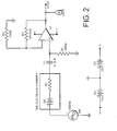
- FIG. 2 there is shown a pCO 2 measurement circuit for use with the sensor of Figure 1 .
- An AC current of frequency 1 kHz is applied to electrodes 5 and 6 when sensor 1 is dipped into the test substance. (Use of an AC current avoids electrolysis).
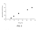
- the sensor of Figure 1 was tested out in vitro using water with different pCO 2 values (as determined with an ABL System 625 blood gas machine) produced by bubbling 100% CO 2 gas through doubly distilled water for different times until the desired pCO 2 values were attained.
- SR 850 lock-in amplifier
- the first stage of this circuit contains a high pass filter (150 Hz) to remove DC signals.
- the input voltage from the signal generator was 6 mV and the values of resistors R 1 , R 2 and R 3 were respectively 1 M ⁇ , 50 k ⁇ and 10 k ⁇ .
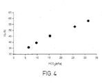
- the output voltage was measured at different pCO 2 values in the range 6 to 31.5 kPa (see Table 1 above). Measurement was repeated six times at each value to ensure reproducibility. During measurement, the current density varied from 1 to 17 ⁇ A/cm 2 which is within the limits of electrode linearity. The measured output voltages plotted against pCO 2 are shown in Figure 3 .
- a substrate 11 of a non-conductive material e.g. silicon or more preferably glass
- a liquid enclosing zone 12 is formed (e.g. machined or etched) to provide a surface of a liquid enclosing zone 12 on or about which first and second electrodes 13 and 14 are laid or deposited, e.g. as wires or printed or vapor deposited conductors.
- the liquid enclosing zone has recesses into which the electrodes are placed so as to ensure that the liquid depth is greater at those locations than in the intervening area.
- the electrodes are electrically connected to a power source (not shown) by leads 15 and 16 which may be covered by an insulator (not shown) to ensure that current flow in the liquid enclosing zone is between the electrodes and through the liquid 17 rather than between the leads to the electrodes.
- the electrodes are desirably 1 to 3 mm in width parallel to the surface of substrate 11 and may for example be formed from platinum, e.g. black platinum, or silver or aluminium.
- the substrate may be of any appropriate depth, e.g. 3 to 50 mm.
- the gap between the electrodes, which as shown are concentric, is preferably at least 0.5 mm, e.g. 0.5 to 3 mm.
- a porous spacer layer 18 e.g.
- a cuprophane membrane (or more preferably a plastics net) which may have a dimension in the micron range, e.g. a thickness of 1 ⁇ m.
- This preferably abuts the surface of the substrate between the electrodes and optionally the substrate surface outside the outer electrode 13.
- This spacer serves both to contain the liquid 17 and to maintain a fixed depth of liquid between the substrate surface and a CO 2 permeable membrane 19 which is disposed over the spacer.
- membrane 19 is sealed (not shown) directly or indirectly to substrate 11 to define a liquid enclosing chamber.
- Membrane 19 is conveniently of Teflon or polysiloxane and suitably is 0.5 to 250 ⁇ m thick, preferably 1 to 50 ⁇ m thick.
- first and second electrodes 20 and 21 are placed in a substrate (e.g. of glass, silicon or teflon) 22, e.g. in channels etched or machined therein or in a sandwich like structure.
- the electrodes are parallel, preferably about 1 mm in length, and preferably spaced apart by at least 1 mm, e.g. 1 to 3 mm.
- the substrate between the electrodes is preferably raised relative to the electrodes and conveniently is either flush with or slightly lower than the surface of the substrate beyond the electrodes.
- a porous spacer 23 e.g.
- a 1 ⁇ m thick cuprophane membrane (or more preferably a plastics net) and over the spacer is sealingly disposed a CO 2 permeable membrane 24, e.g. a 1 ⁇ m thick Teflon membrane.
- the chamber defined by the CO 2 permeable membrane, the substrate and the electrodes is filled with substantially electrolyte free water adjusted to a pH slightly below 7 by addition of HC1.
- spacer 23 may be omitted or may be provided with an aperture over the portion of the substrate between the electrodes and gas permeable membrane 24 replaced by a gas impermeable membrane.
- the surface of the substrate between the electrodes is preferably 0.5 to 2 ⁇ m away from the inner surface of the gas impermeable membrane.
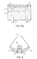
- FIG 8 there is shown a body surface (e.g. organ surface) piercing sensor according to the invention.
- the sensor comprises a curved elongate body member 25 of a plastics material having at one end a sharp, piercing portion 26 and having connected at the other end wires (leads) 27 leading to a power source (not shown).
- a power source not shown
- two electrodes 28,29 are disposed which are electrically connected to wires 27 and covered by a spacer (not shown) and by a CO 2 permeable membrane 30 (shown removed).
- the electrode/spacer/membrane assembly may typically be constructed as described above in relation to Figure 7 .
- the body member is typically about 2 to 6 mm in length and one, or more usually an array, of such sensors may be placed into the surface of an organ during surgery with the leads emerging together through a surgical incision in the skin, generally within or adjacent the post-operative drainage duct. When monitoring of the patient is to cease, the sensors may simply be withdrawn by gentle pulling of the wires 27 outside the body.
- FIG. 9 is a schematic representation of electronics suitable for operating the sensors of the invention.
- An AC current is generated by sine generator 31 and fed to one of the pCO 2 sensor electrodes 32 and to a phase shifter 33.
- the signal from the other pCO 2 electrode 32 is passed to a low noise amplifier 34 and from there to a phase detector 35 where its phase is compared with that of a reference signal generated by phase shifter 33.
- Out of phase components, ie. undesired components, of the amplified signal are rejected and the remaining portion of the amplified signal is fed to signal filter 36 to remove low frequency components.
- the filtered signal is proportional to pCO 2 (or conductance) and is passed on for recordal or further manipulation, e.g. by a chart recorder, a computer or a data logger.
- the pCO 2 sensor shown in Figures 10A-10C comprises a tightly-stretched CO 2 permeable membrane 37 and two electrodes 38 which are connected to the external sensing electronics (not shown) by wires 39.
- the membrane 37 is mounted against a grid 40 in which are defined a plurality of holes through which CO 2 passing the membrane 37 can travel.
- the water in the holes in the grid 40 does not affect the conductivity measurements.
- the grid 40 provides mechanical support for the membrane 37 to prevent pressure changes in the water in the sensor while allowing the passage of CO 2 therethrough.
- the sensor is provided with a cover portion 41 which has defined therein two filler holes 42 through which double distilled water can be passed to fill the water chambers 43 above each electrode 38.
- a bridge chamber 44 which fills with water when the water chambers are filled and provides a relatively low volume/high surface area region for absorption of CO 2 passing through the membrane 37.
- the provision of the bridge chamber 44 permits a the sensitive sensor because the water in the bridge chamber 44 forms the conductive path between the electrodes 38 in use of the sensor, and the relatively low volume and high surface area of this region ensures a relatively large increase in conductivity with CO 2 passing through the membrane 37.
- the water chambers 43 extend above the horizontal level of the bridge chamber 44. This ensures that any air bubbles in the water are retained in the water chambers 43 and do not affect the conductivity of the water in the bridge chamber 44.
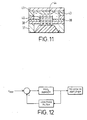
- the pCO 2 sensor shown in Figure 11 is composed of silicon layers bonded together with silicon dioxide and has silver/aluminium electrodes 38.
- the structure of this sensor is similar to that of the sensor of Figures 10A to 10C and like reference numerals have been used for corresponding parts.
- Figure 12 shows a schematic diagram of an improvement to the sensor electronics for the pCO 2 sensor according to the invention. It has been noted that the pCO 2 sensor generates a small DC voltage due to electrolytic effects between the electrodes and the ions in the water. However, pre-amplification of the signal through the pCO 2 sensor can increase the DC current through the sensor to such an extent that the electrodes can degrade resulting in drift of the sensor.
- the capacitor C1 acts to block DC current passing through the sensor and the pre-amplification stage, to prevent drifting problems arising.
- the capacitor results in an extra phase addition to the AC signal which can cause errors in the detection signal measured by the lock-in amplifier.
- a large capacitor is difficult to incorporate into an application specific integrated circuit (ASIC).
- ASIC application specific integrated circuit
- Figure 12 schematically shows an alternative to the capacitor arrangement of Figure 2 in the form of a servo mechanism.
- the output of the pre-amplifier is fed back to its input via a low pass filter.
- only DC components of the output are fed back and cancel any DC current drawn through the pCO 2 sensor. In this way, it is ensured that there is no DC current through the pCO 2 sensor which would degrade the electrodes.
- Figure 13 shows a circuit diagram of an arrangement to implement the low pass filter feedback described above.
- the alternating reference voltage is input at connector TP5 and the output voltage to the lock-in amplifier is output at connector TP4.
- the pCO 2 sensor is represented as component CN2 and is in series between the input and output of the circuit with a load resistor R2.
- An op-amp X1-A is connected with its inverting input and output in parallel across the load resistor R2.
- the DC component of the op-amp output voltage V OUT is passed by means of a low pass filter arrangement (R6, X1-B, C2, R5) with a cut-off frequency of 1Hz to the non-inverting input of the op-amp X1-A.
- a low pass filter arrangement R6, X1-B, C2, R5
- the output voltage V OUT includes a DC component positive feedback via the low pass filter causes the output voltage V OUT to rise.
- This increases the voltage across the load resistor R2 which causes the voltage at the inverting input of the op-amp X1-A to rise to compensate for the increased output voltage.
- the sensor comprises a feedback arrangement for feeding back low frequency, for example DC, components of the output voltage from the sensor in order substantially to cancel low frequency, for example DC, current through the sensor.
- low frequency for example DC
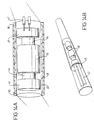
- the sensor shown in Figures 14A and 14B is of a cylindrical configuration but operates on the same principles described in relation to the other embodiments of the pCO 2 sensor.
- the sensor has a plastic core 45 which mounts two ring electrodes 46 which are connected to the external sensing circuitry (not shown) via wires 47.
- the wires 47 are shielded to prevent cross-talk.
- An outer cylinder 48 has defined therein a plurality of holes and acts in the same way as the grid 40 shown in Figures 10A-10C to support the gas permeable membrane 49. Rings 50 hold the membrane 49, cylinder 48 and plastics core 45 in position in the sensor. As shown in Figure 14B the sensor is intended to be received in a catheter so that it can be inserted superficially in an organ of interest. In order to make the catheter biocompatible it may be coated with polyethylene.
- the measuring film of deionised water is located between the plastics core 45 and the membrane 49.
Landscapes
- Health & Medical Sciences (AREA)
- Life Sciences & Earth Sciences (AREA)
- Engineering & Computer Science (AREA)
- Biomedical Technology (AREA)
- Chemical & Material Sciences (AREA)
- Hematology (AREA)
- Physics & Mathematics (AREA)
- Medicinal Chemistry (AREA)
- General Physics & Mathematics (AREA)
- Urology & Nephrology (AREA)
- Biophysics (AREA)
- Food Science & Technology (AREA)
- Ecology (AREA)
- Analytical Chemistry (AREA)
- Biochemistry (AREA)
- General Health & Medical Sciences (AREA)
- Molecular Biology (AREA)
- Immunology (AREA)
- Pathology (AREA)
- Measurement Of The Respiration, Hearing Ability, Form, And Blood Characteristics Of Living Organisms (AREA)
- Investigating Or Analyzing Materials By The Use Of Electric Means (AREA)
- Investigating Or Analysing Biological Materials (AREA)
- Measuring Oxygen Concentration In Cells (AREA)
- Investigating Or Analyzing Materials By The Use Of Fluid Adsorption Or Reactions (AREA)
- Water Treatment By Electricity Or Magnetism (AREA)
- Separation Using Semi-Permeable Membranes (AREA)
- Valve Device For Special Equipments (AREA)
Applications Claiming Priority (3)
| Application Number | Priority Date | Filing Date | Title |
|---|---|---|---|
| GBGB9815667.2A GB9815667D0 (en) | 1998-07-17 | 1998-07-17 | Device |
| GB9815667 | 1998-07-17 | ||
| PCT/GB1999/002315 WO2000004386A2 (en) | 1998-07-17 | 1999-07-19 | Co2 sensor |
Publications (2)
| Publication Number | Publication Date |
|---|---|
| EP1099115A2 EP1099115A2 (en) | 2001-05-16 |
| EP1099115B1 true EP1099115B1 (en) | 2012-04-25 |
Family
ID=10835758
Family Applications (1)
| Application Number | Title | Priority Date | Filing Date |
|---|---|---|---|
| EP99934873A Expired - Lifetime EP1099115B1 (en) | 1998-07-17 | 1999-07-19 | Co2 sensor |
Country Status (12)
| Country | Link |
|---|---|
| US (3) | US6541268B1 (no) |
| EP (1) | EP1099115B1 (no) |
| JP (1) | JP4356826B2 (no) |
| AT (1) | ATE555382T1 (no) |
| AU (1) | AU748570B2 (no) |
| CA (1) | CA2337894C (no) |
| DK (1) | DK1099115T3 (no) |
| ES (1) | ES2388040T3 (no) |
| GB (1) | GB9815667D0 (no) |
| NO (1) | NO329905B1 (no) |
| PT (1) | PT1099115E (no) |
| WO (1) | WO2000004386A2 (no) |
Families Citing this family (25)
| Publication number | Priority date | Publication date | Assignee | Title |
|---|---|---|---|---|
| GB9815667D0 (en) * | 1998-07-17 | 1998-09-16 | Medinnova Sf | Device |
| TR200402453T4 (tr) * | 2000-08-24 | 2004-12-21 | Givaudan Sa | Böcek defedici vasıfları olan bileşim. |
| GB2384713B (en) | 2000-10-31 | 2004-10-27 | Deas Alexander Roger | Integral life support system |
| AT411067B (de) * | 2001-11-30 | 2003-09-25 | Sy Lab Vgmbh | Vorrichtung zur detektion von kohlendioxid |
| GB0324450D0 (en) * | 2003-10-20 | 2003-11-19 | Alertis Medical As | Sensor |
| JP5080251B2 (ja) * | 2004-07-16 | 2012-11-21 | アラーティス メディカル エイエス | 生体内または生体外において生体組織の二酸化炭素分圧を測定するための電気化学センサ |
| EP1788933A1 (en) * | 2004-09-08 | 2007-05-30 | Alertis Medical AS | Sensor |
| US8287724B2 (en) * | 2007-07-05 | 2012-10-16 | Baxter International Inc. | Dialysis fluid measurement systems using conductive contacts |
| US8448499B2 (en) | 2008-12-23 | 2013-05-28 | C A Casyso Ag | Cartridge device for a measuring system for measuring viscoelastic characteristics of a sample liquid, a corresponding measuring system, and a corresponding method |
| US9072899B1 (en) * | 2009-09-04 | 2015-07-07 | Todd Nickloes | Diaphragm pacemaker |
| EP4137199A1 (en) * | 2010-11-17 | 2023-02-22 | Medtronic Ireland Manufacturing Unlimited Company | Systems for therapeutic renal neuromodulation for treating dyspnea |
| EP2713877B1 (de) | 2011-05-23 | 2019-07-31 | Roche Diabetes Care GmbH | Sensorvorrichtung zum nachweis eines analyten |
| DE102011108133A1 (de) | 2011-07-20 | 2013-01-24 | Kurt-Schwabe-Institut für Mess- und Sensortechnik e.V. Meinsberg | Vorrichtung und Verfahren zur Extraktion gelöster Komponenten aus Flüssigkeiten |
| JP6213906B2 (ja) * | 2012-06-22 | 2017-10-18 | オムロン株式会社 | ガスセンサ |
| US10288630B2 (en) | 2014-09-29 | 2019-05-14 | C A Casyso Gmbh | Blood testing system and method |
| US10175225B2 (en) | 2014-09-29 | 2019-01-08 | C A Casyso Ag | Blood testing system and method |
| US10539579B2 (en) | 2014-09-29 | 2020-01-21 | C A Casyso Gmbh | Blood testing system and method |
| US10816559B2 (en) | 2014-09-29 | 2020-10-27 | Ca Casyso Ag | Blood testing system and method |
| US9891209B2 (en) * | 2015-05-29 | 2018-02-13 | C A Casyso Gmbh | Electrode assembly for measurement of platelet function in whole blood |
| EP3329266A4 (en) * | 2015-07-29 | 2019-07-10 | Parker-Hannifin Corporation | SOLID-STATE ELECTRODES AND SENSORS COMPRISING ACTIVE REDOX SURFACE AREAS |
| US10473674B2 (en) | 2016-08-31 | 2019-11-12 | C A Casyso Gmbh | Controlled blood delivery to mixing chamber of a blood testing cartridge |
| US10843185B2 (en) | 2017-07-12 | 2020-11-24 | Ca Casyso Gmbh | Autoplatelet cartridge device |
| GB2581779A (en) | 2019-02-21 | 2020-09-02 | Sensocure As | Sensor |
| CN113167761B (zh) * | 2019-10-15 | 2022-06-03 | 埃克索斯达医疗公司 | 二氧化碳传感器 |
| MX2023006717A (es) * | 2020-12-10 | 2023-08-25 | Caravan Tech Llc | Disposicion, bolo, caravana y metodo para el monitoreo del estado fisiologico de un animal. |
Citations (2)
| Publication number | Priority date | Publication date | Assignee | Title |
|---|---|---|---|---|
| GB1314877A (en) * | 1970-05-01 | 1973-04-26 | Draegerwerk Ag | Apparatus for detecting carbon dioxide |
| GB1368870A (en) * | 1971-09-24 | 1974-10-02 | Draegerwerk Ag | Measurement of carbon dioxide in a gas which is to be inhaled |
Family Cites Families (14)
| Publication number | Priority date | Publication date | Assignee | Title |
|---|---|---|---|---|
| GB2005418B (en) * | 1977-07-26 | 1982-04-21 | Searle & Co | Electrochemical sensor system |
| DK143246C (da) * | 1978-03-28 | 1981-11-30 | Radiometer As | Elektrodeanordning til transcutan p(co2)-maaling |
| JPS5670756A (en) | 1979-11-16 | 1981-06-12 | Ishikawa Seisakusho Kk | Measurement of carbon dioxide gas concentration |
| JPS5858457A (ja) | 1981-09-30 | 1983-04-07 | Shimadzu Corp | 溶液導電率型ガス濃度測定用電極 |
| US4452672A (en) * | 1982-01-07 | 1984-06-05 | University College London | Process and apparatus for polarographic determination of oxygen and carbon dioxide |
| US5526809A (en) * | 1982-03-22 | 1996-06-18 | Mountpelier Investments, S.A. | Hollow viscous and soild organ tonometry |
| US4846937A (en) * | 1983-08-26 | 1989-07-11 | Hnu Systems, Inc. | Method of detecting carbon dioxide in a gaseous or liquid sample |
| JPS62259053A (ja) | 1986-05-02 | 1987-11-11 | Hitachi Ltd | Pco2電極 |
| ATE133047T1 (de) * | 1988-08-26 | 1996-02-15 | Mountpelier Investments | Tonometrische katheter-kombination |
| IT1244609B (it) * | 1990-09-14 | 1994-08-08 | Instrumentation Lab Spa | Procedimento ed apparecchiatura per la determinazione elettrochimica di specie gassose o volatili con particolare riferimento ad emogsanalizzatori. |
| US5333609A (en) * | 1992-05-19 | 1994-08-02 | Minnesota Mining And Manufacturing Company | Catheter and probe-catheter assembly |
| WO1995010975A1 (en) * | 1993-10-18 | 1995-04-27 | Washington Research Foundation | Device and method for monitoring and normalizing physiological parameters |
| JP3163407B2 (ja) | 1994-02-24 | 2001-05-08 | 日本光電工業株式会社 | 生体内ガスセンサ |
| GB9815667D0 (en) * | 1998-07-17 | 1998-09-16 | Medinnova Sf | Device |
-
1998
- 1998-07-17 GB GBGB9815667.2A patent/GB9815667D0/en not_active Ceased
-
1999
- 1999-07-19 AU AU50512/99A patent/AU748570B2/en not_active Expired
- 1999-07-19 EP EP99934873A patent/EP1099115B1/en not_active Expired - Lifetime
- 1999-07-19 DK DK99934873.3T patent/DK1099115T3/da active
- 1999-07-19 AT AT99934873T patent/ATE555382T1/de active
- 1999-07-19 US US09/743,971 patent/US6541268B1/en not_active Expired - Fee Related
- 1999-07-19 PT PT99934873T patent/PT1099115E/pt unknown
- 1999-07-19 JP JP2000560453A patent/JP4356826B2/ja not_active Expired - Lifetime
- 1999-07-19 CA CA002337894A patent/CA2337894C/en not_active Expired - Lifetime
- 1999-07-19 WO PCT/GB1999/002315 patent/WO2000004386A2/en active IP Right Grant
- 1999-07-19 ES ES99934873T patent/ES2388040T3/es not_active Expired - Lifetime
-
2001
- 2001-01-16 NO NO20010261A patent/NO329905B1/no not_active IP Right Cessation
-
2003
- 2003-02-03 US US10/356,951 patent/US7622304B2/en not_active Expired - Fee Related
-
2009
- 2009-10-13 US US12/577,897 patent/US8003401B2/en not_active Expired - Fee Related
Patent Citations (2)
| Publication number | Priority date | Publication date | Assignee | Title |
|---|---|---|---|---|
| GB1314877A (en) * | 1970-05-01 | 1973-04-26 | Draegerwerk Ag | Apparatus for detecting carbon dioxide |
| GB1368870A (en) * | 1971-09-24 | 1974-10-02 | Draegerwerk Ag | Measurement of carbon dioxide in a gas which is to be inhaled |
Also Published As
| Publication number | Publication date |
|---|---|
| AU5051299A (en) | 2000-02-07 |
| PT1099115E (pt) | 2012-07-31 |
| DK1099115T3 (da) | 2012-08-20 |
| WO2000004386A3 (en) | 2000-04-27 |
| ATE555382T1 (de) | 2012-05-15 |
| NO20010261L (no) | 2001-01-16 |
| ES2388040T3 (es) | 2012-10-05 |
| AU748570B2 (en) | 2002-06-06 |
| NO20010261D0 (no) | 2001-01-16 |
| WO2000004386A2 (en) | 2000-01-27 |
| EP1099115A2 (en) | 2001-05-16 |
| GB9815667D0 (en) | 1998-09-16 |
| US7622304B2 (en) | 2009-11-24 |
| US20030178304A1 (en) | 2003-09-25 |
| CA2337894C (en) | 2009-01-27 |
| US8003401B2 (en) | 2011-08-23 |
| JP4356826B2 (ja) | 2009-11-04 |
| US6541268B1 (en) | 2003-04-01 |
| CA2337894A1 (en) | 2000-01-27 |
| JP2002520619A (ja) | 2002-07-09 |
| NO329905B1 (no) | 2011-01-24 |
| US20100044226A1 (en) | 2010-02-25 |
Similar Documents
| Publication | Publication Date | Title |
|---|---|---|
| US8003401B2 (en) | Carbon dioxide sensor and method of determining partial pressure of carbon dioxide | |
| EP1774324B1 (en) | Electrochemical sensor for in-vivo or ex-vivo measurements of the carbon dioxide partial pressure of living tissue | |
| Hahn | Tutorial Review. Electrochemical analysis of clinicalblood-gases, gases and vapours | |
| CA2578078A1 (en) | Sensor | |
| US20080039703A1 (en) | Sensor | |
| Hahn | Techniques for measuring the partial pressures of gases in the blood. I. In vitro measurements | |
| US20210389274A1 (en) | Sensor | |
| Mirtaheri et al. | A new biomedical sensor for measuring PCO2 | |
| EP4114262B1 (en) | Membrane sealing for a physiological sensor | |
| Espadas-Torre et al. | Electrochemical sensors for the continuous monitoring of blood gases and electrolytes |
Legal Events
| Date | Code | Title | Description |
|---|---|---|---|
| PUAI | Public reference made under article 153(3) epc to a published international application that has entered the european phase |
Free format text: ORIGINAL CODE: 0009012 |
|
| 17P | Request for examination filed |
Effective date: 20010206 |
|
| AK | Designated contracting states |
Kind code of ref document: A2 Designated state(s): AT BE CH CY DE DK ES FI FR GB GR IE IT LI LU MC NL PT SE |
|
| AX | Request for extension of the european patent |
Free format text: AL;LT;LV;MK;RO;SI |
|
| GRAP | Despatch of communication of intention to grant a patent |
Free format text: ORIGINAL CODE: EPIDOSNIGR1 |
|
| GRAS | Grant fee paid |
Free format text: ORIGINAL CODE: EPIDOSNIGR3 |
|
| DAX | Request for extension of the european patent (deleted) | ||
| GRAA | (expected) grant |
Free format text: ORIGINAL CODE: 0009210 |
|
| AK | Designated contracting states |
Kind code of ref document: B1 Designated state(s): AT BE CH CY DE DK ES FI FR GB GR IE IT LI LU MC NL PT SE |
|
| REG | Reference to a national code |
Ref country code: GB Ref legal event code: FG4D |
|
| REG | Reference to a national code |
Ref country code: CH Ref legal event code: EP |
|
| REG | Reference to a national code |
Ref country code: AT Ref legal event code: REF Ref document number: 555382 Country of ref document: AT Kind code of ref document: T Effective date: 20120515 |
|
| REG | Reference to a national code |
Ref country code: IE Ref legal event code: FG4D |
|
| RAP2 | Party data changed (patent owner data changed or rights of a patent transferred) |
Owner name: SENSOCURE AS |
|
| REG | Reference to a national code |
Ref country code: DE Ref legal event code: R096 Ref document number: 69944169 Country of ref document: DE Effective date: 20120614 |
|
| REG | Reference to a national code |
Ref country code: PT Ref legal event code: SC4A Free format text: AVAILABILITY OF NATIONAL TRANSLATION Effective date: 20120724 |
|
| REG | Reference to a national code |
Ref country code: NL Ref legal event code: T3 |
|
| REG | Reference to a national code |
Ref country code: SE Ref legal event code: TRGR |
|
| REG | Reference to a national code |
Ref country code: DK Ref legal event code: T3 |
|
| REG | Reference to a national code |
Ref country code: ES Ref legal event code: FG2A Ref document number: 2388040 Country of ref document: ES Kind code of ref document: T3 Effective date: 20121005 |
|
| PG25 | Lapsed in a contracting state [announced via postgrant information from national office to epo] |
Ref country code: CY Free format text: LAPSE BECAUSE OF FAILURE TO SUBMIT A TRANSLATION OF THE DESCRIPTION OR TO PAY THE FEE WITHIN THE PRESCRIBED TIME-LIMIT Effective date: 20120425 |
|
| PG25 | Lapsed in a contracting state [announced via postgrant information from national office to epo] |
Ref country code: GR Free format text: LAPSE BECAUSE OF FAILURE TO SUBMIT A TRANSLATION OF THE DESCRIPTION OR TO PAY THE FEE WITHIN THE PRESCRIBED TIME-LIMIT Effective date: 20120726 |
|
| PG25 | Lapsed in a contracting state [announced via postgrant information from national office to epo] |
Ref country code: MC Free format text: LAPSE BECAUSE OF NON-PAYMENT OF DUE FEES Effective date: 20120731 |
|
| PLBE | No opposition filed within time limit |
Free format text: ORIGINAL CODE: 0009261 |
|
| STAA | Information on the status of an ep patent application or granted ep patent |
Free format text: STATUS: NO OPPOSITION FILED WITHIN TIME LIMIT |
|
| 26N | No opposition filed |
Effective date: 20130128 |
|
| REG | Reference to a national code |
Ref country code: DE Ref legal event code: R097 Ref document number: 69944169 Country of ref document: DE Effective date: 20130128 |
|
| PG25 | Lapsed in a contracting state [announced via postgrant information from national office to epo] |
Ref country code: LU Free format text: LAPSE BECAUSE OF NON-PAYMENT OF DUE FEES Effective date: 20120719 |
|
| REG | Reference to a national code |
Ref country code: FR Ref legal event code: PLFP Year of fee payment: 18 |
|
| REG | Reference to a national code |
Ref country code: FR Ref legal event code: PLFP Year of fee payment: 19 |
|
| REG | Reference to a national code |
Ref country code: FR Ref legal event code: PLFP Year of fee payment: 20 |
|
| PGFP | Annual fee paid to national office [announced via postgrant information from national office to epo] |
Ref country code: FR Payment date: 20180720 Year of fee payment: 20 Ref country code: IT Payment date: 20180720 Year of fee payment: 20 Ref country code: IE Payment date: 20180717 Year of fee payment: 20 Ref country code: NL Payment date: 20180717 Year of fee payment: 20 Ref country code: ES Payment date: 20180801 Year of fee payment: 20 Ref country code: DE Payment date: 20180718 Year of fee payment: 20 |
|
| PGFP | Annual fee paid to national office [announced via postgrant information from national office to epo] |
Ref country code: CH Payment date: 20180718 Year of fee payment: 20 Ref country code: GB Payment date: 20180717 Year of fee payment: 20 Ref country code: FI Payment date: 20180717 Year of fee payment: 20 Ref country code: SE Payment date: 20180723 Year of fee payment: 20 Ref country code: DK Payment date: 20180723 Year of fee payment: 20 Ref country code: AT Payment date: 20180724 Year of fee payment: 20 Ref country code: BE Payment date: 20180717 Year of fee payment: 20 |
|
| PGFP | Annual fee paid to national office [announced via postgrant information from national office to epo] |
Ref country code: PT Payment date: 20180716 Year of fee payment: 20 |
|
| REG | Reference to a national code |
Ref country code: DE Ref legal event code: R071 Ref document number: 69944169 Country of ref document: DE |
|
| REG | Reference to a national code |
Ref country code: DK Ref legal event code: EUP Effective date: 20190719 |
|
| REG | Reference to a national code |
Ref country code: NL Ref legal event code: MK Effective date: 20190718 |
|
| REG | Reference to a national code |
Ref country code: CH Ref legal event code: PL |
|
| REG | Reference to a national code |
Ref country code: GB Ref legal event code: PE20 Expiry date: 20190718 |
|
| REG | Reference to a national code |
Ref country code: IE Ref legal event code: MK9A Ref country code: BE Ref legal event code: MK Effective date: 20190719 |
|
| REG | Reference to a national code |
Ref country code: AT Ref legal event code: MK07 Ref document number: 555382 Country of ref document: AT Kind code of ref document: T Effective date: 20190719 |
|
| PG25 | Lapsed in a contracting state [announced via postgrant information from national office to epo] |
Ref country code: PT Free format text: LAPSE BECAUSE OF EXPIRATION OF PROTECTION Effective date: 20190729 Ref country code: IE Free format text: LAPSE BECAUSE OF EXPIRATION OF PROTECTION Effective date: 20190719 |
|
| PG25 | Lapsed in a contracting state [announced via postgrant information from national office to epo] |
Ref country code: GB Free format text: LAPSE BECAUSE OF EXPIRATION OF PROTECTION Effective date: 20190718 |
|
| REG | Reference to a national code |
Ref country code: ES Ref legal event code: FD2A Effective date: 20201204 |
|
| PG25 | Lapsed in a contracting state [announced via postgrant information from national office to epo] |
Ref country code: ES Free format text: LAPSE BECAUSE OF EXPIRATION OF PROTECTION Effective date: 20190720 |