EP1099113B1 - Ultraschall-prüfeinrichtung - Google Patents
Ultraschall-prüfeinrichtung Download PDFInfo
- Publication number
- EP1099113B1 EP1099113B1 EP99934716A EP99934716A EP1099113B1 EP 1099113 B1 EP1099113 B1 EP 1099113B1 EP 99934716 A EP99934716 A EP 99934716A EP 99934716 A EP99934716 A EP 99934716A EP 1099113 B1 EP1099113 B1 EP 1099113B1
- Authority
- EP
- European Patent Office
- Prior art keywords
- probe
- rail
- subgroup
- test piece
- elements
- Prior art date
- Legal status (The legal status is an assumption and is not a legal conclusion. Google has not performed a legal analysis and makes no representation as to the accuracy of the status listed.)
- Expired - Lifetime
Links
Images


Classifications
-
- G—PHYSICS
- G01—MEASURING; TESTING
- G01N—INVESTIGATING OR ANALYSING MATERIALS BY DETERMINING THEIR CHEMICAL OR PHYSICAL PROPERTIES
- G01N29/00—Investigating or analysing materials by the use of ultrasonic, sonic or infrasonic waves; Visualisation of the interior of objects by transmitting ultrasonic or sonic waves through the object
- G01N29/22—Details, e.g. general constructional or apparatus details
- G01N29/26—Arrangements for orientation or scanning by relative movement of the head and the sensor
- G01N29/262—Arrangements for orientation or scanning by relative movement of the head and the sensor by electronic orientation or focusing, e.g. with phased arrays
-
- B—PERFORMING OPERATIONS; TRANSPORTING
- B61—RAILWAYS
- B61K—AUXILIARY EQUIPMENT SPECIALLY ADAPTED FOR RAILWAYS, NOT OTHERWISE PROVIDED FOR
- B61K9/00—Railway vehicle profile gauges; Detecting or indicating overheating of components; Apparatus on locomotives or cars to indicate bad track sections; General design of track recording vehicles
- B61K9/12—Measuring or surveying wheel-rims
-
- G—PHYSICS
- G01—MEASURING; TESTING
- G01M—TESTING STATIC OR DYNAMIC BALANCE OF MACHINES OR STRUCTURES; TESTING OF STRUCTURES OR APPARATUS, NOT OTHERWISE PROVIDED FOR
- G01M17/00—Testing of vehicles
- G01M17/08—Railway vehicles
- G01M17/10—Suspensions, axles or wheels
-
- G—PHYSICS
- G01—MEASURING; TESTING
- G01N—INVESTIGATING OR ANALYSING MATERIALS BY DETERMINING THEIR CHEMICAL OR PHYSICAL PROPERTIES
- G01N2291/00—Indexing codes associated with group G01N29/00
- G01N2291/10—Number of transducers
- G01N2291/106—Number of transducers one or more transducer arrays
-
- G—PHYSICS
- G01—MEASURING; TESTING
- G01N—INVESTIGATING OR ANALYSING MATERIALS BY DETERMINING THEIR CHEMICAL OR PHYSICAL PROPERTIES
- G01N2291/00—Indexing codes associated with group G01N29/00
- G01N2291/26—Scanned objects
- G01N2291/262—Linear objects
- G01N2291/2623—Rails; Railroads
-
- G—PHYSICS
- G01—MEASURING; TESTING
- G01N—INVESTIGATING OR ANALYSING MATERIALS BY DETERMINING THEIR CHEMICAL OR PHYSICAL PROPERTIES
- G01N2291/00—Indexing codes associated with group G01N29/00
- G01N2291/26—Scanned objects
- G01N2291/269—Various geometry objects
- G01N2291/2696—Wheels, Gears, Bearings
Definitions
- the invention relates to a method for ultrasonic testing in particular designed as a railway wheel test specimen in accordance with the preamble of the claim 1 specified characteristics.
- Such a method for ultrasonic testing is known from US-A-3 978 712, according to which two ultrasonic probe elements are used.
- the two Probe elements are against each other and to a normal to the rail in the contact area a railroad wheel arranged inclined.
- the ultrasonic waves are at a given angle to the normal emitted and introduced in the circumferential direction in the railway wheel, the ultrasonic waves traverse the railway wheel in the circumferential direction.
- the fundamentally linearly propagating ultrasound waves to a circular wave propagation to get distracted.
- some of the ultrasonic waves occur in the contact area out of the wheel and reaches the second as Receiver effective probe element.
- DE-A 195 44 217 describes a method for ultrasonic testing in particular known as a railroad test specimen on which a Test wheel can be unrolled.
- the test wheel contains in the area of its on the Specimen rolling, essentially cylindrical rolling surface a variety of Probe elements, of which a number or subgroup form a probe, the transmitting or receiving sides facing the test specimen each in the contact area the rolling surface and the surface of the test specimen.
- the Test head elements of the activated test head are so-called "phased array technology" operated, with time-defined, delayed control oblique radiation of ultrasonic waves into the test specimen can be specified can.
- a detection device which in particular a laser and a Contains photodetector, the angular position of the test wheel can be detected.
- the object of the invention is the method for ultrasonic testing of the type mentioned to the extent that during the Rolling over a test specimen, in particular a railway wheel, a Detection of defects in the volume and surface of the test specimen guaranteed is.
- the effort involved in handling and evaluating the test should be kept to a minimum be reduced.
- Railway wheels made of different parts and / or different Materials should be able to be checked in a reliable manner, in particular also internal cracks, which originate from the transition between the wheel disc and the wheel rim, should be detected with a high degree of certainty.
- the inventive method for ultrasonic testing is characterized by a Detection of defects, especially internal defects, such as Cracks in the test specimen. So when the test specimen is designed as a railway wheel, which consists of different parts and / or different materials, Errors are detected, for example, from the transition area between the wheel disc and run out the rim.
- a recess or groove of the rail head is a linear array of an array of ultrasonic probes provided in preferably radiate ultrasonic waves into the test specimen free of coupling agents, the angle of incidence of the irradiation of the ultrasonic waves being advantageous can be specified.
- the length of the array is at least as large as the circumference of the
- the test specimen and the test head elements are preferred as electromagnetic ultrasonic transducers educated.
- the test is carried out while the test specimen is rolled over, whereby by means of a detection device, which in particular two position detectors, such as Photoelectric barriers, includes rolling the test specimen into the test head array section as well the speed of the test specimen or wheel is determined.
- the determined and / or calculated speed becomes one with the wheel movement synchronous activation or deactivation of a predetermined number of elements of the array, which form a subgroup.
- the number M of the respective elements of a subgroup will be the largest permissible distance between the two edge elements to the wheel surface and / or the required directional characteristic and / or the required test sensitivity.
- the The number M is between 3 and 11, in particular between 5 and 9.
- the first Subgroup of the linear array with M individual elements activated in such a way that the The point of contact between the wheel and the rail lies symmetrically to the center of the sub-group.
- the activation / trigger time (master trigger) is calculated from the previously determined one Speed of the wheel and the distance from the center of the subgroup to Position of the light barriers. This is done by a trigger module.
- the ultrasound is given as a transverse wave with horizontal polarization Angles between 35 ° and 90 ° to the surface normal are coupled into the wheel.
- the corresponding triggering times of the array elements are calculated from the Master trigger.
- the individual elements of the linear probe array housed in a recess or groove in the rail, so as to prevent mechanical To be protected from wear.
- the output signals together in a control and evaluation circuit can be stored with the measurement signals received by the probe elements, so that starting from a reference position after performing the check, incorrect positions can be located in the test specimen.
- Fig. 1 shows an at least approximately cylindrical test specimen 2, which in particular is designed as a railway wheel, has a tread 4 and around one Drawing plane orthogonal axis 6 is rotatably mounted.
- the test specimen 6 is with its Tread 4 rollable on a running surface 8 of a rail 10, which here as a railroad track is trained.
- the rail 10 contains in the running surface 8 a in the longitudinal direction extending recess or groove 12 with a predetermined number m of Probe elements 14.
- the preferred electromagnetic probe elements 14 are in the Groove 12 integrated in the form of a linear array.
- the number M of sub-group elements is taken into account the largest allowable distance at the two edges of the subgroup located probe elements for tread 4 or wheel surface, the required Directional characteristic of the sound waves emitted by the probe elements and the required test sensitivity.
- the individual probe elements 14 are in the Groove 12 expediently spring-mounted by means of spring elements 18.
- the test device also contains a detection device 20 for determining the Position of the test specimen 2 with respect to a predeterminable starting position, in particular the Arrays of the probe elements 14.
- the detection device 20 contains in particular two Light barriers 22, 23 and a mirror 24 arranged on the test specimen 2 Detection device 20 is like the test head elements 14 with a control and Evaluation circuit 26 connected, in which the supplied signals are evaluated and Control of the test facility can be used. So the respective position of the test specimen 2 to the starting position and also the lateral speed of the test specimen or Railway wheel 2 determined in the longitudinal direction of the rails.
- the position detection device 20 By means of the position detection device 20 is the rolling of the test specimen in the test head array path and the Speed of the wheel in connection with the evaluation circuit 26 determined and the activation or deactivation of the specified synchronized with the wheel movement Number of probe elements of the respective subgroup of the array controlled.
- Position data and the lateral wheel speed is displayed when the test specimen rolls 2 on the rail 10 each have a sub-group with the number M of probe elements 2 activated in such a way that it is symmetrical to the respective support or contact point 16 lie.
- one test head element is used switched off the subgroup and added a new element until the Perimeter or tread 4 over the entire linear array of probe elements 14 is unrolled.
- the ultrasonic waves After reflection of ultrasound waves at defects 30 in the volume area 32 or in the transition from the wheel rim 34 and wheel disc 38, the ultrasonic waves in Dependence of the positions of the test specimen determined by means of the detection device 20 2 evaluated with the control and evaluation circuit 26. It should be noted that by means of the ultrasound test device according to the invention without the use of coupling means, such as water or the like, checking between the test specimen and the rail is carried out.
- test specimen 2 shows an enlarged part of the test specimen 2 and some of the support point 16 Adjacent probe elements, to which reference numerals 41 to 53 are assigned. It be assumed that the test specimen 2 is about its axis of rotation in the direction of Arrow 56 rotates so that the test specimen 2 on the rail 10 in the direction of arrow 58 rolls laterally, the axis of rotation lying on the normal 60 in the support point 16.
- the individual probe elements are not in the here by means of the spring elements 18 mentioned further shown rail resilient, the for reasons of clarity Spring elements of the five test head elements 45 to 49 closest to the normal 60 are not are shown.
- the five test head elements 45 to 49 mentioned form a subgroup 62.
- the test probe elements of subgroup 62 are not excited at the same time, but successively with a delay 64 so that the sound in the test specimen 2 obliquely, namely at an angle 66 to the normal 60 is sonicated.
- the total runtime delay 64 will meet the respective requirements correspondingly specified for the desired insonification angle 66.
- the number M of Test specimen of subgroup 62 is made according to the respective framework conditions given, the largest permissible distance between the two edge elements of the subgroup, 2, it is the outer edge elements 45 and 49 to the running or surface 4 of the test specimen 2, furthermore the required directional characteristic or the insonification angle 66 and the required test sensitivity when specifying the number M of Subgroup 62 are taken into account.
- the number M is preferably between 3 and 11 Specified in particular between 5 and 9.
- the delay 64 in the time-shifted excitation of the individual elements of subgroup 62 being the Ultrasound as a transverse wave with preferably horizontal polarization under the Incidence angle 66 in a range between 90 ° and 35 ° to the normal 60 in the test specimen 2 is coupled.
- Fig. 3 shows the test specimen 2 in a position which the test specimen 2 shortly after Assumes position according to FIG. 2. It now becomes the sub-group 62 'with the probe elements 46 to 50 activated or controlled with the delay 64. Compared 2, the probe element 45 is switched off, while the probe element 50 is switched on. The middle probe element of subgroup 62 'is now that Probe element 48 through which the normal 60 runs. As can be seen, this is also here the point of contact 16 in the center of the subgroup 62 '.
- the activation or trigger time which is called the master trigger is derived from the previously determined Speed of the test specimen 2 and the distance from the center of the subgroup 62 ' determined for the position of the detection device explained above and in particular by means of the evaluation and control circuit 26 is calculated. The delayed activation times of the individual probe elements of the activated subgroup are created from the Master trigger calculated.
- the probe element 14 contains one of a high-frequency coil 68 wrapped, magnetizable semicircular toroid 70, the ends 72 of which face the measuring side 74 in a casting block 76 is arranged.
- Rod-shaped permanent magnets are located between the ends 72 of the ring band core 70 78 arranged in the longitudinal direction between the ends 72 of the Ring toroid core 70 extend.
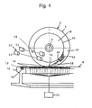
- FIG. 5 shows a cross section through a test head element 14 integrated into the rail 10, which is firmly mounted in the groove 12 of the rail 10, so that the measuring side 74 a Has distance 80 to the rail surface or running surface 8.
- the distance is 80 in particular between 0.1 to 0.2 mm.
- the electrical connection lines 82 of the RF coil 68 for signal excitation in the case of transmission and signal reception in the case of reception arranged in a cable duct 84 integrated into the rail 10 and not further here shown connected to the explained evaluation and control circuit.
- FIG. 6 shows a section along section line A according to FIG. 5 with the five activated Probe elements 45 to 49 of the sub-group. That of the central element 47, over which the point of contact 16 is distant edge probe elements 45 and 49 have an enlarged gap 86 with respect to the wheel 2 in accordance with its diameter on. This larger gap leads to a reduced excitation of the edge elements 45 and 49 of the subgroup and correspondingly also of the elements 46 and 48.
- the edge elements 45, 46 and 48, 49 of the subgroup shown here the same applies to the activated subgroup, a higher amplitude is applied to the excitation delayed in the transit time.
- FIGS. 5, 6, show another embodiment, similar to FIGS. 5, 6, in the groove 12 the rail 10 integrated probe elements 45 to 49. These probe elements are by means of a gimbal 88 and a spring element 90 in the groove 12 of the Rail 10 arranged.
- the respective probe elements of the active subgroup adhere as a result of the magnetic holding forces, in particular on the basis of FIG. 4 explained ring band core and / or the permanent magnets, on the tread 4 and uniform excitation of all probe elements of the activated subgroup is made possible.
Landscapes
- Physics & Mathematics (AREA)
- General Physics & Mathematics (AREA)
- Health & Medical Sciences (AREA)
- Engineering & Computer Science (AREA)
- Life Sciences & Earth Sciences (AREA)
- Chemical & Material Sciences (AREA)
- Analytical Chemistry (AREA)
- Biochemistry (AREA)
- General Health & Medical Sciences (AREA)
- Mechanical Engineering (AREA)
- Immunology (AREA)
- Pathology (AREA)
- Investigating Or Analyzing Materials By The Use Of Ultrasonic Waves (AREA)
Description
- Fig. 1
- eine perspektivische Ansicht eines auf einer Schiene abrollenden Prüfkörpers,
- Fig. 2, 3
- schematisch einen Längsschnitt im Bereich des Berührungspunktes zwischen Prüfkörper und Schiene,
- Fig. 4
- ein Ausführungsbeispiel eines Prüfkopfelements ,
- Fig. 5
- vergrößert einen Schnitt quer zur Längsrichtung der Schiene,
- Fig. 6
- einen Schnitt entlang Schnittlinie A gemäß Fig. 5,
- Fig. 7
- vergrößert einen Schnitt durch ein weiteres Ausführungsbeispiel quer zur Längsrichtung der Schiene,
- Fig. 8
- einen Schnitt entlang Schnittlinie B gemäß Fig. 7.
- 2
- Prüfkörper
- 4
- Lauffläche von 2
- 6
- Achse von 2
- 8
- Fahrfläche von 10
- 10
- Schiene
- 12
- Ausnehmung / Nut in 10
- 14
- Prüfkopfelement
- 16
- Auflagepunkt / Berührungspunkt
- 18
- Federelement
- 20
- Detektionsvorrichtung
- 22, 23
- Lichtschranke
- 24
- Spiegel
- 26
- Auswerte- und Steuerschaltung
- 28
- Ultraschallwelle
- 30
- Fehler
- 32
- Volumenbereich
- 34
- Radkranz
- 36
- Bohrungsfläche
- 38
- Radscheibe
- 41 - 53
- Prüfkopfelement
- 56
- Pfeil / Drehrichtung
- 58
- Pfeil / laterale Bewegung
- 60
- Normale
- 62
- Untergruppe
- 64
- Laufzeitverzögerung
- 66
- Einschallwinkel
- 68
- Hochfrequenzspule
- 70
- Ringbandkern
- 72
- Ende von 70
- 74
- Meßseite
- 76
- Vergußblock
- 78
- Permanentmagnet
- 80
- Abstand
- 82
- elektrische Anschlußleitung
- 84
- Kabelkanal
- 86
- Spalt
- 88
- kardanische Aufhängung
- 90
- Federelement
Claims (5)
- Verfahren zur Ultraschallprüfung eines insbesondere als Eisenbahnrad ausgebildeten Prüfkörpers (2), welcher über eine Lauffläche (4) auf einer Fahrfläche (8) einer Schiene (10) entlang rollbar ist, wobei in der Schiene (10) wenigstens ein Ultraschall-Prüfkopfelement (14) angeordnet ist zum Aussenden von Ultraschallwellen unter einem vorgegebenen Winkel (66) zur Normalen (60) der Schiene (10) in den Prüfkörper (2) und zum Empfang von in den Prüfkörper (2) ausgesendeten und insbesondere auf Fehlstellen desselben treffenden Ultraschallwellen,
dadurch gekennzeichnet, dass eine Anzahl (m) von Prüfkopfelementen (14) als lineares Array in einer Nut (12) der Schiene (10) angeordnet sind, wobei die Anzahl (m) zumindest gleich groß ist wie der Quotient aus dem Umfang der Lauffläche (4) und der in Längsrichtung der Schiene gemessenen Breite der nebeneinander angeordneten einzelnen Prüfkopfelemente (14),
dass eine Untergruppe (62) mit einer vorgegebenen Anzahl (M) der Prüfkopfelemente (14) aktiviert wird, welche sich im Bereich der Auflagelinie (16) der Lauffläche (4) auf der Fahrfläche (8) befindet,
dass mittels einer Detektionsvorrichtung (20) das Einrollen des Prüfkörpers (2) in das Prüfkopfarray festgestellt wird und ferner die Geschwindigkeit des Prüfkörpers (2) berechnet wird,
dass zur Ultraschallprüfung des aus verschiedenen Teilen oder unterschiedlichen Materialien bestehenden Prüfkörpers (2) die Prüfkopfelemente (14) der jeweils aktivierten Untergruppe (62) mit einer Laufzeitverzögerung (64) derart angesteuert werden, dass die Ultraschallwellen mit horizontaler Polarisation in einen Volumenbereich (32) des Prüfkörpers (2) eingeleitet und an den Fehlstellen reflektiert werden,
und dass ferner in Abhängigkeit der Geschwindigkeit des Prüfkörpers (2) eine synchrone Aktivierung bzw. Deaktivierung jeweils eines Prüfkopfelementes der Untergruppe (62) erfolgt. - Verfahren nach Anspruch 1, dadurch gekennzeichnet, dass die Anzahl (M) der jeweils aktivierten Prüfkopfelemente (14) der Untergruppe (62) zwischen 3 bis 11, insbesondere zwischen 5 bis 9, beträgt.
- Verfahren nach Anspruch 1 oder 2, dadurch gekennzeichnet, dass durch federnde Lagerung, insbesondere durch Federelemente (18) in der Schiene (10), die Prüfkopfelemente (14) der jeweils aktivierten Untergruppe (62) zur direkten Anlage an der Lauffläche (4) des Prüfkörpers (2) gebracht werden.
- Verfahren nach einem der Ansprüche 1 bis 3, dadurch gekennzeichnet, dass die Prüfkopfelemente (14) der jeweils aktivierten Untergruppe (62) mittels kardanischer Aufhängung (88) in der Schiene (10) zur direkten Anlage an die Lauffläche (4) des Prüfkörpers (2) gebracht werden.
- Verfahren nach einem der Ansprüche 1 bis 4, dadurch gekennzeichnet, dass die jeweils in der aktivierten Untergruppe (62) neben demjenigen zentralen Prüfkopfelement, durch welches in der Berührungslinie (16) die Normale (60) läuft, liegenden Prüfkopfelemente (14) mit einer höheren Amplitude beaufschlagt werden als das genannte zentrale Prüfkopfelement, wobei die genannten anderen Prüfkopfelemente (14) insbesondere symmetrisch zum zentralen Prüfkopfelement liegen.
Applications Claiming Priority (3)
| Application Number | Priority Date | Filing Date | Title |
|---|---|---|---|
| DE19833034 | 1998-07-22 | ||
| DE19833034 | 1998-07-22 | ||
| PCT/EP1999/005198 WO2000005577A1 (de) | 1998-07-22 | 1999-07-21 | Ultraschall-prüfeinrichtung |
Publications (2)
| Publication Number | Publication Date |
|---|---|
| EP1099113A1 EP1099113A1 (de) | 2001-05-16 |
| EP1099113B1 true EP1099113B1 (de) | 2003-04-23 |
Family
ID=7874962
Family Applications (1)
| Application Number | Title | Priority Date | Filing Date |
|---|---|---|---|
| EP99934716A Expired - Lifetime EP1099113B1 (de) | 1998-07-22 | 1999-07-21 | Ultraschall-prüfeinrichtung |
Country Status (5)
| Country | Link |
|---|---|
| US (1) | US6347550B1 (de) |
| EP (1) | EP1099113B1 (de) |
| DE (2) | DE59905207D1 (de) |
| ES (1) | ES2200533T3 (de) |
| WO (1) | WO2000005577A1 (de) |
Families Citing this family (25)
| Publication number | Priority date | Publication date | Assignee | Title |
|---|---|---|---|---|
| DE10025724B4 (de) * | 2000-05-25 | 2006-05-24 | Hegenscheidt-Mfd Gmbh & Co. Kg | Verfahren und Maschine zum Bearbeiten von Eisenbahnrädern |
| WO2001098769A1 (de) * | 2000-06-20 | 2001-12-27 | Fraunhofer Gesellschaft Zur Förderung Der Angewandten Forschung E. V. | Vorrichtung und verfahren zur prüfung eines eisenbahnrades |
| DE10052045C2 (de) * | 2000-06-20 | 2002-06-27 | Fraunhofer Ges Forschung | Vorrichtung und Verfahren zur Prüfung eines Eisenbahnrades |
| US6553838B2 (en) * | 2000-08-25 | 2003-04-29 | Em-Tech Llc | Detection of anomalies on railroad tracks |
| US6571636B1 (en) * | 2000-09-14 | 2003-06-03 | Cf&I Steel, L.P. | Wheel-type transmit/receive ultrasonic inspection device with constant length internal liquid soundpath |
| GB2373050A (en) * | 2001-02-09 | 2002-09-11 | Central Research Lab Ltd | Method of analysing the condition of a surface using wheel sound detection |
| US6862936B2 (en) * | 2002-11-27 | 2005-03-08 | The Johns Hopkins University | Laser-air, hybrid, ultrasonic testing of railroad wheels |
| NL1028325C2 (nl) * | 2005-02-17 | 2006-08-21 | Sonimex B V | Werkwijze alsmede inrichting voor het detecteren van fouten in een railkop. |
| US8161818B2 (en) * | 2008-10-29 | 2012-04-24 | Airbus Operations Gmbh | Device for detecting a flaw in a component |
| US8177115B1 (en) | 2010-03-12 | 2012-05-15 | Craig Mercier | Method and system for retreading track wheel |
| US8662375B2 (en) | 2010-03-12 | 2014-03-04 | Craig Mercier | Method and system for retreading track wheel |
| DE102010023028A1 (de) * | 2010-06-08 | 2011-12-08 | Fraunhofer-Gesellschaft zur Förderung der angewandten Forschung e.V. | EMUS-Wandlersystem sowie ein Verfahren zur Erzeugung linear polarisierter Transversalwellen mit variabel vorgebbarer Polarisationsrichtung innerhalb eines Prüfkörpers |
| CA2839662C (en) * | 2011-06-22 | 2016-08-16 | Nippon Steel & Sumitomo Metal Corporation | Ultrasonic testing method of wheel |
| CA2872008C (en) * | 2012-04-30 | 2017-10-31 | Craig MERCIER | Method and system for retreading track wheel |
| DE102014119056A1 (de) * | 2014-12-18 | 2016-06-23 | Ge Sensing & Inspection Technologies Gmbh | Verfahren zur Detektion eines Fehlers wie eines Risses in einer Region-of-Interest in einem um eine Rotationsachse drehbaren Eisenbahnrad sowie Vorrichtung hierzu |
| US20160305915A1 (en) * | 2015-04-16 | 2016-10-20 | Transportation Technology Center, Inc. | System for inspecting rail with phased array ultrasonics |
| CN104964834A (zh) * | 2015-07-02 | 2015-10-07 | 常州市常超电子研究所有限公司 | 高铁轮辋自动检测液浸探头 |
| CN105067290A (zh) * | 2015-07-16 | 2015-11-18 | 常州市常超电子研究所有限公司 | 高铁轮辋水膜接触法探头 |
| US10151625B2 (en) | 2016-07-01 | 2018-12-11 | General Electric Company | Inspection system for turbine rotors |
| CN106114554B (zh) * | 2016-07-14 | 2018-06-01 | 南京拓控信息科技股份有限公司 | 一种列车车轮随动式智能探伤系统及方法 |
| EP3495767B1 (de) * | 2017-12-11 | 2022-01-05 | Butler Engineering & Marketing S.p.A. | Einheit zur erfassung geometrischer merkmale einer komponente eines bereiften rades eines fahrzeugs |
| US10946451B2 (en) | 2018-09-14 | 2021-03-16 | Hegenscheidt-Mfd Gmbh | Method and device for the machining of the wheel running surface of wheels for rail vehicles |
| CN110286158A (zh) * | 2019-07-17 | 2019-09-27 | 西安热工研究院有限公司 | 一种可调节入射角度的超声波斜探头 |
| CN110672722B (zh) * | 2019-11-07 | 2022-08-05 | 山东泰威声电信息技术有限公司 | 基于电磁超声的机车车轮踏面缺陷在线检测系统及方法 |
| CN112305070B (zh) * | 2020-10-23 | 2022-12-20 | 中铁山桥集团有限公司 | 一种60at道岔尖轨横波超声检测对比试块及检测方法 |
Family Cites Families (9)
| Publication number | Priority date | Publication date | Assignee | Title |
|---|---|---|---|---|
| US3558876A (en) * | 1968-10-16 | 1971-01-26 | Servo Corp Of America | Train wheel defect detector |
| US3978712A (en) * | 1971-11-17 | 1976-09-07 | Scanning Systems, Inc. | Method and apparatus for testing wear, size and residual stress conditions |
| US4050292A (en) * | 1976-10-18 | 1977-09-27 | Krautkramer-Branson, Incorporated | Method and apparatus for testing railroad wheels |
| EP0282615A1 (de) * | 1987-03-17 | 1988-09-21 | SIGNALTECHNIK GmbH | Anordnung zum Detektieren von Radschäden |
| FR2689242B1 (fr) * | 1992-03-30 | 1994-07-01 | Valdunes | Dispositif de mesure automatique des contraintes residuelles dans la jante d'une roue d'un essieu, monte de chemin de fer. |
| FR2692671B1 (fr) * | 1992-06-18 | 1994-09-30 | Valdunes | Dispositif de contrôle de la jante d'une roue de chemin de fer. |
| DE19544217C2 (de) * | 1995-01-14 | 1997-03-20 | Fraunhofer Ges Forschung | Ultraschallprüfvorrichtung |
| CH690851A5 (fr) * | 1996-11-25 | 2001-02-15 | Speno Internat S A | Dispositif de mesure des défauts internes d'un rail par ultrasons. |
| US5864065A (en) * | 1997-11-25 | 1999-01-26 | Amsted Industries Incorporated | Test apparatus for a railway wheel |
-
1999
- 1999-07-21 ES ES99934716T patent/ES2200533T3/es not_active Expired - Lifetime
- 1999-07-21 US US09/744,150 patent/US6347550B1/en not_active Expired - Fee Related
- 1999-07-21 DE DE59905207T patent/DE59905207D1/de not_active Expired - Lifetime
- 1999-07-21 DE DE19981380T patent/DE19981380D2/de not_active Expired - Fee Related
- 1999-07-21 WO PCT/EP1999/005198 patent/WO2000005577A1/de not_active Ceased
- 1999-07-21 EP EP99934716A patent/EP1099113B1/de not_active Expired - Lifetime
Also Published As
| Publication number | Publication date |
|---|---|
| ES2200533T3 (es) | 2004-03-01 |
| DE59905207D1 (de) | 2003-05-28 |
| EP1099113A1 (de) | 2001-05-16 |
| WO2000005577A1 (de) | 2000-02-03 |
| DE19981380D2 (de) | 2001-11-22 |
| US6347550B1 (en) | 2002-02-19 |
Similar Documents
| Publication | Publication Date | Title |
|---|---|---|
| WO2000005577A1 (de) | Ultraschall-prüfeinrichtung | |
| DE19543481C2 (de) | Vorrichtung zur Prüfung von ferromagnetischen Materialien | |
| DE3751714T2 (de) | Verfahren und Apparatur zum Ultraschallnachweis von Rissen | |
| EP1101105B1 (de) | Verfahren und vorrichtung zur detektion eines risses in einem eisenbahnrad | |
| EP1098803B1 (de) | Verfahren und vorrichtung zum prüfen eines eisenbahnrads | |
| EP2251685A1 (de) | Vorrichtung und Verfahren zur Ultraschalluntersuchung | |
| EP3521773A1 (de) | Ultraschall-durchflussmessvorrichtung und verfahren zum bestimmen einer strömungsgeschwindigkeit | |
| EP3709014A1 (de) | Wandleranordnung für ultraschall-prüfkopfsysteme, ultraschall-prüfkopfsystem und prüfverfahren | |
| WO2001098769A1 (de) | Vorrichtung und verfahren zur prüfung eines eisenbahnrades | |
| WO2017174391A1 (de) | Ultraschall-prüfkopf und ultraschall-prüfanlage | |
| DE2657957C2 (de) | Vorrichtung zur Ultraschallprüfung von Werkstücken | |
| DE102015108720A1 (de) | Ultraschall-Prüfvorrichtung und Verfahren zur zerstörungsfreien Prüfung eines Rades und einer Radscheibe | |
| DE3218453A1 (de) | Verfahren, anordnung und schaltung zur zerstoerungsfreien pruefung der laufflaeche von eisenbahnraedern mittels ultraschall-oberflaechenwellen | |
| DE19943215C2 (de) | Verfahren und Vorrichtung zur Detektion eines Fehlers mittels Ultraschall | |
| DE19544217C2 (de) | Ultraschallprüfvorrichtung | |
| WO2001011353A2 (de) | Ultraschall-sensoranordnung | |
| EP0722085A1 (de) | Ultraschallprüfvorrichtung | |
| DE3715914C2 (de) | ||
| DE102014104914B4 (de) | Vorrichtung und Verfahren zur zerstörungsfreien Prüfung eines Prüflings mittels Ultraschall nach der Vergleichskörpermethode | |
| DE10052045C2 (de) | Vorrichtung und Verfahren zur Prüfung eines Eisenbahnrades | |
| DE3511768C2 (de) | Elektromagnetischer Wandler | |
| EP2673630A1 (de) | Verfahren zur positionserfassung eines defekts in einem körper | |
| EP4382904B1 (de) | Prüfkopfsonde zur ultraschall-prüfung von radsatzwellen mit innenliegender längsbohrung | |
| EP3781938A1 (de) | Vorrichtung und verfahren zur bestimmung der ausdehnung von fehlstellen mittels v-durchschallung | |
| EP4088109A1 (de) | Zerstörungsfreie werkstoffprüfung |
Legal Events
| Date | Code | Title | Description |
|---|---|---|---|
| PUAI | Public reference made under article 153(3) epc to a published international application that has entered the european phase |
Free format text: ORIGINAL CODE: 0009012 |
|
| 17P | Request for examination filed |
Effective date: 20001130 |
|
| AK | Designated contracting states |
Kind code of ref document: A1 Designated state(s): AT BE CH CY DE DK ES FI FR GB GR IE IT LI LU MC NL PT SE |
|
| 17Q | First examination report despatched |
Effective date: 20020308 |
|
| GRAH | Despatch of communication of intention to grant a patent |
Free format text: ORIGINAL CODE: EPIDOS IGRA |
|
| GRAH | Despatch of communication of intention to grant a patent |
Free format text: ORIGINAL CODE: EPIDOS IGRA |
|
| GRAA | (expected) grant |
Free format text: ORIGINAL CODE: 0009210 |
|
| AK | Designated contracting states |
Designated state(s): DE DK ES FR GB IT |
|
| PG25 | Lapsed in a contracting state [announced via postgrant information from national office to epo] |
Ref country code: IT Free format text: LAPSE BECAUSE OF FAILURE TO SUBMIT A TRANSLATION OF THE DESCRIPTION OR TO PAY THE FEE WITHIN THE PRESCRIBED TIME-LIMIT;WARNING: LAPSES OF ITALIAN PATENTS WITH EFFECTIVE DATE BEFORE 2007 MAY HAVE OCCURRED AT ANY TIME BEFORE 2007. THE CORRECT EFFECTIVE DATE MAY BE DIFFERENT FROM THE ONE RECORDED. Effective date: 20030423 |
|
| REG | Reference to a national code |
Ref country code: GB Ref legal event code: FG4D Free format text: NOT ENGLISH |
|
| GBT | Gb: translation of ep patent filed (gb section 77(6)(a)/1977) |
Effective date: 20030423 |
|
| REF | Corresponds to: |
Ref document number: 59905207 Country of ref document: DE Date of ref document: 20030528 Kind code of ref document: P |
|
| PG25 | Lapsed in a contracting state [announced via postgrant information from national office to epo] |
Ref country code: DK Free format text: LAPSE BECAUSE OF FAILURE TO SUBMIT A TRANSLATION OF THE DESCRIPTION OR TO PAY THE FEE WITHIN THE PRESCRIBED TIME-LIMIT Effective date: 20030723 |
|
| RAP2 | Party data changed (patent owner data changed or rights of a patent transferred) |
Owner name: FRAUNHOFER-GESELLSCHAFT ZUR FOERDERUNG DERANGEWAND |
|
| ET | Fr: translation filed | ||
| PLBE | No opposition filed within time limit |
Free format text: ORIGINAL CODE: 0009261 |
|
| STAA | Information on the status of an ep patent application or granted ep patent |
Free format text: STATUS: NO OPPOSITION FILED WITHIN TIME LIMIT |
|
| REG | Reference to a national code |
Ref country code: ES Ref legal event code: FG2A Ref document number: 2200533 Country of ref document: ES Kind code of ref document: T3 |
|
| 26N | No opposition filed |
Effective date: 20040126 |
|
| REG | Reference to a national code |
Ref country code: DE Ref legal event code: R084 Ref document number: 59905207 Country of ref document: DE Effective date: 20130311 |
|
| PGFP | Annual fee paid to national office [announced via postgrant information from national office to epo] |
Ref country code: ES Payment date: 20140721 Year of fee payment: 16 Ref country code: FR Payment date: 20140724 Year of fee payment: 16 Ref country code: GB Payment date: 20140721 Year of fee payment: 16 |
|
| GBPC | Gb: european patent ceased through non-payment of renewal fee |
Effective date: 20150721 |
|
| PG25 | Lapsed in a contracting state [announced via postgrant information from national office to epo] |
Ref country code: GB Free format text: LAPSE BECAUSE OF NON-PAYMENT OF DUE FEES Effective date: 20150721 |
|
| REG | Reference to a national code |
Ref country code: FR Ref legal event code: ST Effective date: 20160331 |
|
| PG25 | Lapsed in a contracting state [announced via postgrant information from national office to epo] |
Ref country code: FR Free format text: LAPSE BECAUSE OF NON-PAYMENT OF DUE FEES Effective date: 20150731 |
|
| PGFP | Annual fee paid to national office [announced via postgrant information from national office to epo] |
Ref country code: DE Payment date: 20160721 Year of fee payment: 18 |
|
| REG | Reference to a national code |
Ref country code: ES Ref legal event code: FD2A Effective date: 20170127 |
|
| PG25 | Lapsed in a contracting state [announced via postgrant information from national office to epo] |
Ref country code: ES Free format text: LAPSE BECAUSE OF NON-PAYMENT OF DUE FEES Effective date: 20150722 |
|
| REG | Reference to a national code |
Ref country code: DE Ref legal event code: R119 Ref document number: 59905207 Country of ref document: DE |
|
| PG25 | Lapsed in a contracting state [announced via postgrant information from national office to epo] |
Ref country code: DE Free format text: LAPSE BECAUSE OF NON-PAYMENT OF DUE FEES Effective date: 20180201 |