EP1098779B1 - Roue avec jante ayant des sieges inclines vers l'exterieur - Google Patents
Roue avec jante ayant des sieges inclines vers l'exterieur Download PDFInfo
- Publication number
- EP1098779B1 EP1098779B1 EP99932741A EP99932741A EP1098779B1 EP 1098779 B1 EP1098779 B1 EP 1098779B1 EP 99932741 A EP99932741 A EP 99932741A EP 99932741 A EP99932741 A EP 99932741A EP 1098779 B1 EP1098779 B1 EP 1098779B1
- Authority
- EP
- European Patent Office
- Prior art keywords
- rim
- support
- wheel
- wheel according
- support ring
- Prior art date
- Legal status (The legal status is an assumption and is not a legal conclusion. Google has not performed a legal analysis and makes no representation as to the accuracy of the status listed.)
- Expired - Lifetime
Links
- 229910052751 metal Inorganic materials 0.000 claims description 6
- 239000002184 metal Substances 0.000 claims description 6
- 238000012806 monitoring device Methods 0.000 claims description 3
- 238000002788 crimping Methods 0.000 claims description 2
- 238000003466 welding Methods 0.000 claims description 2
- 238000006073 displacement reaction Methods 0.000 claims 2
- 238000004026 adhesive bonding Methods 0.000 claims 1
- 238000003780 insertion Methods 0.000 claims 1
- 230000037431 insertion Effects 0.000 claims 1
- 229920001971 elastomer Polymers 0.000 description 3
- 239000011324 bead Substances 0.000 description 2
- 238000005096 rolling process Methods 0.000 description 2
- 239000010959 steel Substances 0.000 description 2
- 239000012815 thermoplastic material Substances 0.000 description 2
- 229910000838 Al alloy Inorganic materials 0.000 description 1
- 229910000851 Alloy steel Inorganic materials 0.000 description 1
- RRHGJUQNOFWUDK-UHFFFAOYSA-N Isoprene Chemical compound CC(=C)C=C RRHGJUQNOFWUDK-UHFFFAOYSA-N 0.000 description 1
- 229910000831 Steel Inorganic materials 0.000 description 1
- 241001080024 Telles Species 0.000 description 1
- 229910052782 aluminium Inorganic materials 0.000 description 1
- XAGFODPZIPBFFR-UHFFFAOYSA-N aluminium Chemical compound [Al] XAGFODPZIPBFFR-UHFFFAOYSA-N 0.000 description 1
- 238000004519 manufacturing process Methods 0.000 description 1
- 238000012544 monitoring process Methods 0.000 description 1
- 229920001195 polyisoprene Polymers 0.000 description 1
- 238000003825 pressing Methods 0.000 description 1
- 239000011800 void material Substances 0.000 description 1
- 230000004584 weight gain Effects 0.000 description 1
- 235000019786 weight gain Nutrition 0.000 description 1
Images


Classifications
-
- B—PERFORMING OPERATIONS; TRANSPORTING
- B60—VEHICLES IN GENERAL
- B60C—VEHICLE TYRES; TYRE INFLATION; TYRE CHANGING; CONNECTING VALVES TO INFLATABLE ELASTIC BODIES IN GENERAL; DEVICES OR ARRANGEMENTS RELATED TO TYRES
- B60C7/00—Non-inflatable or solid tyres
-
- B—PERFORMING OPERATIONS; TRANSPORTING
- B60—VEHICLES IN GENERAL
- B60B—VEHICLE WHEELS; CASTORS; AXLES FOR WHEELS OR CASTORS; INCREASING WHEEL ADHESION
- B60B3/00—Disc wheels, i.e. wheels with load-supporting disc body
- B60B3/02—Disc wheels, i.e. wheels with load-supporting disc body with a single disc body integral with rim
-
- B—PERFORMING OPERATIONS; TRANSPORTING
- B60—VEHICLES IN GENERAL
- B60B—VEHICLE WHEELS; CASTORS; AXLES FOR WHEELS OR CASTORS; INCREASING WHEEL ADHESION
- B60B21/00—Rims
- B60B21/02—Rims characterised by transverse section
-
- B—PERFORMING OPERATIONS; TRANSPORTING
- B60—VEHICLES IN GENERAL
- B60B—VEHICLE WHEELS; CASTORS; AXLES FOR WHEELS OR CASTORS; INCREASING WHEEL ADHESION
- B60B21/00—Rims
- B60B21/02—Rims characterised by transverse section
- B60B21/023—Rims characterised by transverse section the transverse section being non-symmetrical
-
- B—PERFORMING OPERATIONS; TRANSPORTING
- B60—VEHICLES IN GENERAL
- B60B—VEHICLE WHEELS; CASTORS; AXLES FOR WHEELS OR CASTORS; INCREASING WHEEL ADHESION
- B60B21/00—Rims
- B60B21/02—Rims characterised by transverse section
- B60B21/026—Rims characterised by transverse section the shape of rim well
-
- B—PERFORMING OPERATIONS; TRANSPORTING
- B60—VEHICLES IN GENERAL
- B60B—VEHICLE WHEELS; CASTORS; AXLES FOR WHEELS OR CASTORS; INCREASING WHEEL ADHESION
- B60B21/00—Rims
- B60B21/02—Rims characterised by transverse section
- B60B21/028—Rims characterised by transverse section the shape of hump
-
- B—PERFORMING OPERATIONS; TRANSPORTING
- B60—VEHICLES IN GENERAL
- B60B—VEHICLE WHEELS; CASTORS; AXLES FOR WHEELS OR CASTORS; INCREASING WHEEL ADHESION
- B60B21/00—Rims
- B60B21/10—Rims characterised by the form of tyre-seat or flange, e.g. corrugated
- B60B21/102—Rims characterised by the form of tyre-seat or flange, e.g. corrugated the shape of bead seats
-
- B—PERFORMING OPERATIONS; TRANSPORTING
- B60—VEHICLES IN GENERAL
- B60B—VEHICLE WHEELS; CASTORS; AXLES FOR WHEELS OR CASTORS; INCREASING WHEEL ADHESION
- B60B21/00—Rims
- B60B21/10—Rims characterised by the form of tyre-seat or flange, e.g. corrugated
- B60B21/104—Rims characterised by the form of tyre-seat or flange, e.g. corrugated the shape of flanges
-
- B—PERFORMING OPERATIONS; TRANSPORTING
- B60—VEHICLES IN GENERAL
- B60B—VEHICLE WHEELS; CASTORS; AXLES FOR WHEELS OR CASTORS; INCREASING WHEEL ADHESION
- B60B21/00—Rims
- B60B21/12—Appurtenances, e.g. lining bands
Definitions
- the subject of the invention is a wheel, composed of a disc and a rim, for pneumatic, and capable of possibly forming, with a support ring for the tire tread and tire, a rolling assembly which can be useful in the case of driving where the inflation pressure drops abnormally compared to at normal operating pressure, called nominal working pressure, pressure which can even become void.
- European application EP-A-0 807 539 describes, by way of example, a wheel according to the preamble of claim 1, intended for effectively solve the above problem.
- This wheel includes, section view meridian, a rim with first and second rim seats, at least the first rim seat having a generator whose axially outer end is on a circle of diameter smaller than the diameter of the circle on which the end is axially inside, the first rim seat being extended axially outside by a projection or hump of low height, and axially inside by a span intended to receive a tread support ring, and a wheel disc, assembled on the side of the first rim seat to the radially inner wall of the rim.
- This wheel is such that the range rim, intended to receive the support ring, is provided with raised elements separated by recesses or hollows.
- the subject of the invention is a wheel which appreciably improves the previous wheel.
- This wheel R is composed of a rim with first and second rim seats, at least the first rim seat having a generator whose axially outer end is on a circle with a diameter smaller than the diameter of the circle on which the end is located axially inside, said first rim seat being extended axially outside by a projection or hump of low height, and axially inside by a bearing intended to receive a tread support ring, and a wheel disc, joined from the side of the first rim seat to the radially inner wall of the rim.
- This wheel R is characterized in that the rim seat consists of a first and a second support zones separated by a circumferential groove opening radially externally.
- This wheel has the advantage of significantly reducing the weight of the wheel.
- the circumferential groove can advantageously serve as a housing for a device for pressure monitoring.
- This wheel has the advantage of having two support zones reduced to a minimum which allows remarkable weight gain.
- the support function of the ring support is provided by a generally annular support, with or without holes and which can be attached to the wheel in a removable manner or not, or even attached to the support ring. This wheel allows in particular to draw full-face wheels of weight acceptable.
- the wheel according to the invention may have a rim made from a metal sheet, steel or aluminum alloy.
- the disc can also be produced from such a sheet metallic.
- the connection between the disc and the rim is then advantageously carried out by fitting under the circumferential throat.
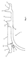
- FIG. 1 shows, in meridian and schematic view, a one-piece wheel 1 such that disclosed by patent application EP 0 807 539.
- This wheel comprises a rim 10 with two 13 'and 13 "rim seats with equal diameters and inclined generators outwards. The two seats are extended externally by projections or humps 15 'and 15 ".
- the outer seat 13' is extended axially inwards by a seat 11, itself provided at its other end with a positioning stop 16 of a ring support intended to be mounted on this seat 11.
- the 13 "interior seat is extended axially inside by a rim flange 14, flange delimiting with the stop positioning 16 a mounting groove 12.
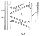
- the bearing surface 11 is provided with triangular-shaped recesses 111. These recesses 111 are delimited axially by the transverse ribs 113 of the bearing and circumferentially by circumferential ribs 112.
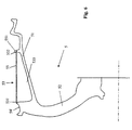
- Wheel 2 shown in Figure 3 (a) largely incorporates the characteristics of the wheel 1 presented in FIG. 1. It differs therefrom, however, in that the diameters of the two seats 23 'and 23 "are uneven, the first seat 23', arranged on the outside of the wheel 2, having a diameter smaller than that of the second seat 23 ". This makes it possible to reduce the depth of mounting groove 22.
- the bearing surface 21 of this wheel 2 is constituted by a first 211 and a second 212 support zones separated by a circumferential groove 213 opening radially outward.
- This circumferential groove makes it possible to substantially reduce the weight of the wheel 2 relative to the wheel 1 and greatly facilitates its production.
- the bearing surface 212 comprises a radially outer projection 26 serving as an axial stop for support.
- This projection can also be radially inner 26 ′ as illustrated in the figure 3 (b).
- the inner surface of the support has a rib of suitable shape to come to hang inside when it is mounted on wheel 2.
- Such support is preferably made of rubber (see Figure 5).
- the wheel 2 also has a valve hole 24 disposed in the outer flank 214 of the circumferential groove 213. This valve hole opens to the outside of the disc 20.
- the two support zones 211 and 212 are adapted to support a support ring such than that presented, in meridian section, in FIG. 4.
- This support ring 3 includes an annular apex 31 intended to come into contact with the tread of the tire in the event of a severe decrease in the tire inflation pressure.
- feet 32 and 33 extend radially inward from the top. These feet have their end adapted to come into abutment, when the support ring is mounted on the wheel 2, against the two support zones 211 and 212. Lugs 34, 35 coming to bear against the internal sides 214 and 215 of the support zones 211 and 212, prevent any axial sliding towards the outside of the circumferential groove 213 of the feet 32 and 33.
- the ring of support 3 can in particular be made of reinforced thermoplastic material.
- the form of the support ring allows its ovalization when it is mounted in a tire, prior to mounting the pneumatic assembly and support ring around the wheel 3.
- a such support ring 4 has a base 41, of generally annular shape and reinforced by a longitudinally oriented ply 411, a vertex 42, substantially annular, with on its radially outer wall longitudinal grooves 421 and a annular body 43 for connection between the base and the top.
- the annular connecting body 43 comprises a first massive part 431 as well as a second part 432 comprising recesses extending axially over substantially more than half of the body 43 and opening on the outside of the support. These recesses are regularly distributed over the body circumference 43 and define radial walls.
- the two support zones may have a surface insufficient and this limits the effectiveness of rolling in support.
- FIG. 6 shows a one-piece wheel 5, in which the bearing 53 comprises two support zones 531 and 532 separated by a circumferential groove 533.
- the two support zones serve to support a support 55 of a support ring similar to that of FIG. 5.
- the support 55 is annular and is a metallic ferrule with a projection 551, radially outer and disposed at its axially inner end, intended to block the axial movement of the support ring.
- the support 55 is rigidly fixed to the bearing surface 53, for example by welding, crimping or bonding. It can also be detachably attached or be part of the support ring.
- This embodiment of a wheel according to the invention makes it possible to very significantly increase the axial width of the circumferential groove 533 and therefore greatly reduce the weight wheel total. This is especially important when designing wheels, such as that of FIG. 6, the disc 52 of which is joined to the rim 51 directly under the seat 54 'exterior (full-face wheel).
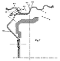
- FIG. 7 shows a wheel 6, similar to the monobloc wheel 2 of FIG. 3, but obtained by assembling a rim 61 and a disc 62 made from steel sheets. The assembly is carried out by fitting the disc 62 under the circumferential groove 613. As before, the valve 65 crosses the external flank of the groove 613 through the hole 64 and opens to the outside of the disc 62.
- the wheel 6 can also be made of sheet metal aluminum.
- the base 41 of the support 4 preferably has its external geometry adapted to come to bear against the flank 614 and the support area 612.
- the circumferential groove of the wheels according to the invention can advantageously serve as housing of a tire pressure monitoring device.
- This device 8 can in particular be fixed to the valve 65 as illustrated in FIG. 8.
Landscapes
- Engineering & Computer Science (AREA)
- Mechanical Engineering (AREA)
- Tires In General (AREA)
Applications Claiming Priority (3)
| Application Number | Priority Date | Filing Date | Title |
|---|---|---|---|
| FR9809387 | 1998-07-20 | ||
| FR9809387A FR2781184A1 (fr) | 1998-07-20 | 1998-07-20 | Roue avec jante ayant des sieges inclines vers l'exterieur |
| PCT/EP1999/004463 WO2000005083A1 (fr) | 1998-07-20 | 1999-06-28 | Roue avec jante ayant des sieges inclines vers l'exterieur |
Publications (2)
| Publication Number | Publication Date |
|---|---|
| EP1098779A1 EP1098779A1 (fr) | 2001-05-16 |
| EP1098779B1 true EP1098779B1 (fr) | 2002-04-24 |
Family
ID=9528917
Family Applications (1)
| Application Number | Title | Priority Date | Filing Date |
|---|---|---|---|
| EP99932741A Expired - Lifetime EP1098779B1 (fr) | 1998-07-20 | 1999-06-28 | Roue avec jante ayant des sieges inclines vers l'exterieur |
Country Status (14)
| Country | Link |
|---|---|
| US (1) | US6470936B2 (enExample) |
| EP (1) | EP1098779B1 (enExample) |
| JP (1) | JP2002521251A (enExample) |
| KR (1) | KR100602405B1 (enExample) |
| CN (1) | CN1137825C (enExample) |
| AU (1) | AU747482B2 (enExample) |
| BR (1) | BR9912290A (enExample) |
| CA (1) | CA2337318A1 (enExample) |
| DE (1) | DE69901348T2 (enExample) |
| ES (1) | ES2175997T3 (enExample) |
| FR (1) | FR2781184A1 (enExample) |
| HU (1) | HU222828B1 (enExample) |
| PL (1) | PL345582A1 (enExample) |
| WO (1) | WO2000005083A1 (enExample) |
Families Citing this family (19)
| Publication number | Priority date | Publication date | Assignee | Title |
|---|---|---|---|---|
| FR2805214B1 (fr) * | 2000-02-21 | 2002-04-05 | Michelin Soc Tech | Jante et ensemble d'une telle jante avec un appui de soutien |
| CA2327370A1 (fr) * | 2000-12-05 | 2002-06-05 | Hydro-Quebec | Nouvelle methode de fabrication de li4ti5o12 pur a partir du compose ternaire tix-liy-carbone: effet du carbone sur la synthese et la conductivite de l'electrode |
| FR2817800A1 (fr) | 2000-12-13 | 2002-06-14 | Michelin Soc Tech | Roue avec jante ayant des sieges inclines vers l'exterieur et realisee par un procede d'extrusion |
| FR2818585A1 (fr) | 2000-12-22 | 2002-06-28 | Michelin Soc Tech | Ensemble d'une jante et d'un appui de soutien |
| FR2831107B1 (fr) | 2001-10-18 | 2004-10-15 | Michelin Soc Tech | Procede d'estimation de la temperature de l'air de la cavite interne d'un pneumatique et application a la detection d'un fonctionnement anormal d'un systeme de roulage a plat |
| FR2836865B1 (fr) | 2002-03-11 | 2004-05-14 | Michelin Soc Tech | Roue avec jante composite realisee par procede rtm |
| FR2841825B1 (fr) * | 2002-07-08 | 2004-08-27 | Michelin Soc Tech | Jante de roue constituee de deux structures assemblees |
| JP3808858B2 (ja) * | 2003-10-07 | 2006-08-16 | 住友ゴム工業株式会社 | サポートリング、及びタイヤ組立体 |
| FR2861334B1 (fr) | 2003-10-24 | 2006-01-06 | Michelin Soc Tech | Appui de securite a endurance amelioree |
| FR2862023B1 (fr) * | 2003-11-10 | 2006-01-06 | Michelin Soc Tech | Appui de securite allege pour pneumatique |
| ITMI20072231A1 (it) * | 2007-11-26 | 2009-05-27 | Campagnolo Srl | Cerchio per ruota di bicicletta e ruota di bicicletta comprendente tale cerchio |
| US20120086263A1 (en) * | 2009-06-05 | 2012-04-12 | Central Motor Wheel Co., Ltd. | Automotive wheel |
| EP2459391B1 (de) | 2009-09-17 | 2013-03-06 | Otto Fuchs KG | Kraftfahrzeugrad sowie verfahren zum herstellen eines kraftfahrzeugrades |
| US9724961B2 (en) * | 2011-12-06 | 2017-08-08 | Mubea Carbo Tech Gmbh | Wheel made out of fiber reinforced material and procedure to make an according wheel |
| CN102922945A (zh) * | 2012-10-09 | 2013-02-13 | 浙江金固股份有限公司 | 一种双凸峰钢制商用车轮 |
| EP3256332B1 (en) | 2015-02-11 | 2023-06-07 | Mubea Carbo Tech GmbH | Method to produce a fiber reinforced rim and a device for producing a fiber reinforced rim |
| US9937781B1 (en) | 2016-12-19 | 2018-04-10 | GM Global Technology Operations LLC | Battery pack mounting architecture with shear plate for electric drive motor vehicles |
| US20240375432A1 (en) * | 2023-05-08 | 2024-11-14 | Maxion Wheels Holding Gmbh | Vehicle wheel rim, vehicle wheel including such a wheel rim and method for producing such a wheel rim and vehicle wheel |
| US20240375433A1 (en) * | 2023-05-08 | 2024-11-14 | Maxion Wheels Holding Gmbh | Vehicle wheel rim, vehicle wheel including such a wheel rim and method for producing such a wheel rim and vehicle wheel |
Family Cites Families (10)
| Publication number | Priority date | Publication date | Assignee | Title |
|---|---|---|---|---|
| GB2000733B (en) * | 1977-07-07 | 1982-03-24 | Ohtsu Tire & Rubber Co Ltd | Safety wheel |
| US4293016A (en) * | 1980-03-24 | 1981-10-06 | The General Tire & Rubber Co. | Pneumatic tire assembly |
| IT1153525B (it) | 1982-06-11 | 1987-01-14 | Pirelli | Cerchio antidetallonamento per pneumatici per autoveicoli |
| FR2552028B1 (fr) | 1983-09-15 | 1987-10-30 | Michelin & Cie | Jante en une seule piece conformee de maniere a retenir le bourrelet sur son siege et procede de montage de l'enveloppe sur sa jante |
| US4953291A (en) * | 1988-12-09 | 1990-09-04 | Grumman Aerospace Corporation | Tire interior support system |
| US5000241A (en) * | 1989-05-09 | 1991-03-19 | Patecell Theodore C | Unitary bead-lock and run-flat roller support ring for pneumatic tires on two-part wheels |
| FR2699121B1 (fr) * | 1992-12-11 | 1995-03-17 | Michelin & Cie | Ensemble formé d'un pneumatique, d'une jante et d'un anneau de soutien. |
| FR2746347A1 (fr) * | 1996-03-19 | 1997-09-26 | Michelin & Cie | Appui de securite en materiau elastomerique souple pour pneumatique |
| FR2748695B1 (fr) | 1996-05-15 | 1998-06-26 | Michelin & Cie | Roue avec jante ayant des sieges inclines vers l'exterieur |
| DE19721860A1 (de) * | 1996-05-22 | 1997-11-27 | Mannesmann Ag | Geschweißtes Fahrzeugrad |
-
1998
- 1998-07-20 FR FR9809387A patent/FR2781184A1/fr active Pending
-
1999
- 1999-06-28 CA CA002337318A patent/CA2337318A1/fr not_active Abandoned
- 1999-06-28 KR KR1020017000813A patent/KR100602405B1/ko not_active Expired - Fee Related
- 1999-06-28 HU HU0104818A patent/HU222828B1/hu not_active IP Right Cessation
- 1999-06-28 CN CNB998110787A patent/CN1137825C/zh not_active Expired - Fee Related
- 1999-06-28 ES ES99932741T patent/ES2175997T3/es not_active Expired - Lifetime
- 1999-06-28 DE DE69901348T patent/DE69901348T2/de not_active Expired - Fee Related
- 1999-06-28 JP JP2000561057A patent/JP2002521251A/ja active Pending
- 1999-06-28 AU AU49016/99A patent/AU747482B2/en not_active Ceased
- 1999-06-28 BR BR9912290-1A patent/BR9912290A/pt not_active IP Right Cessation
- 1999-06-28 WO PCT/EP1999/004463 patent/WO2000005083A1/fr not_active Ceased
- 1999-06-28 EP EP99932741A patent/EP1098779B1/fr not_active Expired - Lifetime
- 1999-06-28 PL PL99345582A patent/PL345582A1/xx not_active Application Discontinuation
-
2001
- 2001-01-18 US US09/765,130 patent/US6470936B2/en not_active Expired - Fee Related
Also Published As
| Publication number | Publication date |
|---|---|
| HUP0104818A3 (en) | 2002-12-28 |
| KR20010053573A (ko) | 2001-06-25 |
| DE69901348D1 (de) | 2002-05-29 |
| FR2781184A1 (fr) | 2000-01-21 |
| CN1137825C (zh) | 2004-02-11 |
| US6470936B2 (en) | 2002-10-29 |
| ES2175997T3 (es) | 2002-11-16 |
| CA2337318A1 (fr) | 2000-02-03 |
| PL345582A1 (en) | 2001-12-17 |
| HUP0104818A2 (hu) | 2002-04-29 |
| EP1098779A1 (fr) | 2001-05-16 |
| HU222828B1 (hu) | 2003-11-28 |
| US20010020506A1 (en) | 2001-09-13 |
| AU747482B2 (en) | 2002-05-16 |
| CN1318018A (zh) | 2001-10-17 |
| WO2000005083A1 (fr) | 2000-02-03 |
| KR100602405B1 (ko) | 2006-07-20 |
| JP2002521251A (ja) | 2002-07-16 |
| DE69901348T2 (de) | 2002-10-31 |
| AU4901699A (en) | 2000-02-14 |
| BR9912290A (pt) | 2001-06-05 |
Similar Documents
| Publication | Publication Date | Title |
|---|---|---|
| EP1098779B1 (fr) | Roue avec jante ayant des sieges inclines vers l'exterieur | |
| CA2178217C (fr) | Jante, anneau de soutien et ensemble comprenant lesdits elements | |
| EP1206357B1 (fr) | Ensemble d'une jante et d'un appui de soutien | |
| EP1097823B1 (fr) | Jante destinée à recevoir un anneau de soutien | |
| FR2713558A1 (fr) | Pneumatique, jante, anneau de soutien et ensemble comprenant lesdits éléments. | |
| EP0807539B1 (fr) | Roue avec jante ayant des sièges inclinés vers l'extérieur | |
| WO1994013498A1 (fr) | Pneumatique, jante, anneau de soutien et ensemble comprenant lesdits elements | |
| EP1216850B1 (fr) | Ensemble d'une jante et d'un appui de soutien | |
| EP0790141A1 (fr) | Jante de roue à rayons destinée à être équipée d'un pneumatique sans chambre, et roue à rayons ainsi équipée | |
| EP1289779B1 (fr) | Pneumatique comprenant un profile de renfort dans au moins un flanc et ensemble monte pneumatique/jante | |
| WO1992010373A1 (fr) | Jante a sieges inclines et ensemble d'une telle jante avec un pneumatique | |
| EP1868823B1 (fr) | Anneau de verrouillage dans un ensemble de montage d'un pneumatique sur un moyeu de vehicule | |
| EP1341678B1 (fr) | Roue avec jante ayant des sieges inclines vers l'exterieur et realisee par un procede d'extrusion | |
| EP1259387B1 (fr) | Jante et ensemble d'une telle jante avec un appui de soutien | |
| EP1551648B1 (fr) | Jante de roue constituee de deux structures assemblees | |
| FR2809348A1 (fr) | Pneumatique comprenant un profile de renfort dans au moins un flanc et ensemble pneumatique/jante comprenant un tel pneumatique | |
| CH633222A5 (en) | Wheel rim and tyre assembly | |
| FR2842140A1 (fr) | Ensemble monte tubeless pour cycle, jante et pneumatique tubeless | |
| EP0192939A1 (fr) | Flap pour pneumatiques | |
| FR2889110A1 (fr) | Ensemble roue et pneumatique avec des sieges de diametres inegaux dont le pneumatique comporte des flancs de largeur superieure a la jante | |
| FR2809054A1 (fr) | Pneumatique, ensemble pneumatique et jante | |
| CH633221A5 (en) | Wheel rim and tyre assembly |
Legal Events
| Date | Code | Title | Description |
|---|---|---|---|
| PUAI | Public reference made under article 153(3) epc to a published international application that has entered the european phase |
Free format text: ORIGINAL CODE: 0009012 |
|
| 17P | Request for examination filed |
Effective date: 20010220 |
|
| AK | Designated contracting states |
Kind code of ref document: A1 Designated state(s): DE ES FR GB IT |
|
| GRAG | Despatch of communication of intention to grant |
Free format text: ORIGINAL CODE: EPIDOS AGRA |
|
| 17Q | First examination report despatched |
Effective date: 20010618 |
|
| GRAG | Despatch of communication of intention to grant |
Free format text: ORIGINAL CODE: EPIDOS AGRA |
|
| GRAH | Despatch of communication of intention to grant a patent |
Free format text: ORIGINAL CODE: EPIDOS IGRA |
|
| REG | Reference to a national code |
Ref country code: GB Ref legal event code: IF02 |
|
| GRAH | Despatch of communication of intention to grant a patent |
Free format text: ORIGINAL CODE: EPIDOS IGRA |
|
| GRAA | (expected) grant |
Free format text: ORIGINAL CODE: 0009210 |
|
| AK | Designated contracting states |
Kind code of ref document: B1 Designated state(s): DE ES FR GB IT |
|
| REG | Reference to a national code |
Ref country code: GB Ref legal event code: FG4D Free format text: NOT ENGLISH |
|
| REF | Corresponds to: |
Ref document number: 69901348 Country of ref document: DE Date of ref document: 20020529 |
|
| GBT | Gb: translation of ep patent filed (gb section 77(6)(a)/1977) |
Effective date: 20020720 |
|
| REG | Reference to a national code |
Ref country code: ES Ref legal event code: FG2A Ref document number: 2175997 Country of ref document: ES Kind code of ref document: T3 |
|
| PLBE | No opposition filed within time limit |
Free format text: ORIGINAL CODE: 0009261 |
|
| STAA | Information on the status of an ep patent application or granted ep patent |
Free format text: STATUS: NO OPPOSITION FILED WITHIN TIME LIMIT |
|
| 26N | No opposition filed |
Effective date: 20030127 |
|
| PGFP | Annual fee paid to national office [announced via postgrant information from national office to epo] |
Ref country code: GB Payment date: 20060615 Year of fee payment: 8 |
|
| PGFP | Annual fee paid to national office [announced via postgrant information from national office to epo] |
Ref country code: ES Payment date: 20060629 Year of fee payment: 8 |
|
| GBPC | Gb: european patent ceased through non-payment of renewal fee |
Effective date: 20070628 |
|
| PG25 | Lapsed in a contracting state [announced via postgrant information from national office to epo] |
Ref country code: GB Free format text: LAPSE BECAUSE OF NON-PAYMENT OF DUE FEES Effective date: 20070628 |
|
| REG | Reference to a national code |
Ref country code: ES Ref legal event code: FD2A Effective date: 20070629 |
|
| PGFP | Annual fee paid to national office [announced via postgrant information from national office to epo] |
Ref country code: IT Payment date: 20080624 Year of fee payment: 10 |
|
| PG25 | Lapsed in a contracting state [announced via postgrant information from national office to epo] |
Ref country code: ES Free format text: LAPSE BECAUSE OF NON-PAYMENT OF DUE FEES Effective date: 20070629 |
|
| PGFP | Annual fee paid to national office [announced via postgrant information from national office to epo] |
Ref country code: DE Payment date: 20080620 Year of fee payment: 10 |
|
| PGFP | Annual fee paid to national office [announced via postgrant information from national office to epo] |
Ref country code: FR Payment date: 20090615 Year of fee payment: 11 |
|
| PG25 | Lapsed in a contracting state [announced via postgrant information from national office to epo] |
Ref country code: DE Free format text: LAPSE BECAUSE OF NON-PAYMENT OF DUE FEES Effective date: 20100101 |
|
| REG | Reference to a national code |
Ref country code: FR Ref legal event code: ST Effective date: 20110228 |
|
| PG25 | Lapsed in a contracting state [announced via postgrant information from national office to epo] |
Ref country code: IT Free format text: LAPSE BECAUSE OF NON-PAYMENT OF DUE FEES Effective date: 20090628 |
|
| PG25 | Lapsed in a contracting state [announced via postgrant information from national office to epo] |
Ref country code: FR Free format text: LAPSE BECAUSE OF NON-PAYMENT OF DUE FEES Effective date: 20100630 |