EP1098468B1 - Verfahren un Vorrichtung für Mehrfachzugriff in einem Kommunikationssystem - Google Patents
Verfahren un Vorrichtung für Mehrfachzugriff in einem Kommunikationssystem Download PDFInfo
- Publication number
- EP1098468B1 EP1098468B1 EP99402766A EP99402766A EP1098468B1 EP 1098468 B1 EP1098468 B1 EP 1098468B1 EP 99402766 A EP99402766 A EP 99402766A EP 99402766 A EP99402766 A EP 99402766A EP 1098468 B1 EP1098468 B1 EP 1098468B1
- Authority
- EP
- European Patent Office
- Prior art keywords
- network
- network terminal
- central station
- assigned
- transform
- Prior art date
- Legal status (The legal status is an assumption and is not a legal conclusion. Google has not performed a legal analysis and makes no representation as to the accuracy of the status listed.)
- Expired - Lifetime
Links
Images
Classifications
-
- H—ELECTRICITY
- H04—ELECTRIC COMMUNICATION TECHNIQUE
- H04L—TRANSMISSION OF DIGITAL INFORMATION, e.g. TELEGRAPHIC COMMUNICATION
- H04L5/00—Arrangements affording multiple use of the transmission path
- H04L5/02—Channels characterised by the type of signal
Definitions
- the present invention relates to a multiple access method, to a transmitter and a receiver adapted to perform such a multiple access method, as are respectively described in the preamble of claims 1, 4 and 6.
- a multiple access method as well as a transmitter and a receiver adapted to perform such a method are already known in the art, e.g. from the article "A New Look at Digital Orthogonal Transmultiplexers for CDMA Communications'; by A.N. Akansu, M.V. Tazebay and R. A. Haddad, IEEE Trans . On Signal Processing, Vol 45, Nr1, Jan 1997 .
- Fig. 1b a code division multiple access, hereafter abbreviated with CDMA, transmitters and receiver are shown.
- CDMA code division multiple access
- each user network terminal is assigned a unique code to enable the central station which is coupled to it in a point to multipoint way, to discriminate the data from each of these network terminals on the basis of this unique code.
- this code is multiplied with the oversampled data symbols by means of a sign change, which operation can be considered as equivalent to a discrete time filtering of this oversampled symbol with a filter having this code as its impulse response.
- a plurality of receive filters are present, whereby each of them is linked with a respective user network terminal, after which the signal is undersampled again.
- the CDMA method has proven to be an efficient multiple access flat spectrum technique. However it looses efficiency when the users are not synchronous . Moreover when the communication channels are dispersive the ability to discriminate between several users vanishes.
- An object of the present invention is to therefore provide a multiple access method, as well as a transmitter and receiver of the above known type but wherein the aforementioned problems of loss of orthogonality in the presence of dispersive channels or non-synchronous users, are solved, while still keeping the advantage of the flat spectrum.
- this object is achieved due to the fact that the method includes the steps as described in the characterizing portion of the first claim and that the transmitter and receiver are further adapted as is described in claims 4 and 6.
- the present invention also relates to a network terminal and a central station which include a transmitter, resp. a receiver previously described, as is further stated by claims 8 and 9.
- the present invention further relates to a communications network wherein the aforementioned method is applied, as is described in claims 10 and 11.
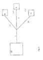
- the communications network of Fig. 1 is composed of a central station CS and a first plurality of network terminals T1, ..., Ti, ... to Tn.
- the central station is coupled to these network terminals via the cascade connection of a common transmission link denoted L and for instance consisting of a copper link for a power line communications, abbreviated with PLC, network, and respective individual network terminal links L1,...,Li,...,Ln, also for instance consisting of copper cables in the case of the aforementioned PLC network.
- L common transmission link
- L for instance consisting of a copper link for a power line communications
- L1 for instance consisting of a copper link for a power line communications
- L1 for instance consisting of a copper link for a power line communications
- L1 for instance consisting of a copper link for a power line communications
- L1 for instance consisting of a copper link for a power line communications
- L1 for instance consisting of a copper link for a power line communications
- the communications network hence has a point-to-multipoint architecture in the downstream direction, which is the direction from the central station CS to the network terminals T1 to Tn, and a multipoint-to-point architecture in the upstream direction, i.e. the direction from the network terminals T1 to Tn towards the central station CS.
- Networks having such a point-to-multipoint architecture in the downstream direction are for instance the already mentioned PLC, UMTS networks and satellite networks.
- the network terminals T1 to Tn commonly share the common transmission link L in a multiplexed way.
- this multiplexing consists for instance of multiplexing in the time domain, called TDMA which stands for time domain multiple access and meaning that different network terminals transmit information to the central station CS in different timeslots.
- This method is currently used in for instance the asynchronous passive optical network, abbreviated with APON, and in GSM networks. In this method timeslots are allocated to the individual user network terminals.
- Another multiple access method, called orthogonal frequency division multiplexing consists of allocating specific frequencies or frequency sub-bands of the total frequency spectrum of the common channel to the individual network terminals.
- Yet another multiple access method consists of the code division multiple access, hereafter abbreviated with CDMA, which is presently used in the aforementioned UMTS and satellite networks.
- CDMA code division multiple access
- the entire frequency band of the common channel is shared by the multitude of network terminals by coding the information such that transmitter and receiver can only discriminate the transmitted and received data on the basis of the code.
- orthogonal codes thereby in theory allows for a perfect discrimination amongst the different users.
- even using these orthogonal codes does not always guarantee a perfect synchronisation, especially in the presence of Doppler effect, terminal interference etc., where data coded differently is corrupted and misinterpreted as originating from another terminal.
- phase division multiple access which is called phase division multiple access, and abbreviated with ⁇ DMA or PHIDMA
- a distinct and unique variable is allocated to each network terminal, being similar to the CDMA method.
- this variable consists of a unique code
- this unique variable consists of a complex number or vector in the z-plane for the PHIDMA.
- CDMA the code is used for encoding the to be transmitted symbols, whereby this complete operation can be considered as an oversampling followed by a filter, which finite impulse response is equal to the code.
- the complex vector assigned to each terminal is to be understood as a complex zero of an all-pass filter, whereby all active network terminals perform such an all-pass filtering operation using all the zero's of all other terminals, except their own.
- ⁇ 1 , ⁇ i-1 , ⁇ i , ⁇ i+1 , ⁇ n ⁇ 1 -1* , ⁇ i-1 -1* , ⁇ i -1* , ⁇ i+1 -1* , ⁇ n -1* respectively denote the unique complex variables and the complex conjugate of their inverse value, which are assigned to respective network terminals T1,...,Ti-1,Ti,Ti+1,...,Tn of the communication system
- C i is a normalisation parameter
- the poles of an all-pass filter are the complex conjugates of the inverse values of the zeroes of this all-pass filter, per definition of an all-pass filter.
- knowing the zero's implicitely reveals the knowledge of the poles such that the complete transfer function in the z-plane is known.
- the zeroes are lying outside the unity circle, being the circle with radius one, in the z-plane, in order to ensure that the complex conjugates of their inverse values, being the poles of the all-pass filter, lie within this unity circle, guaranteeing the stability of such a filter operation.
- the assignment of the respective unique variables to the respective terminals of the communication system is usually performed by the system administrator or manager having a complete knowledge of the complete communications network.
- a possible method can consist of selecting these zeroes as equidistant points in the complex z-plane on a circle with radius 2, thus by dividing the circumference by n and selecting the thus obtained vectors for attribution. These then are stored within the network terminals as well as within the central station.
- n complex number within the z-plane outside the unity-radius circle The modulus of the selected zero however directly influences the length of the response, the peak to average ratio of the signal and to signal to interference plus noise ratio after demodulation.
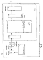
- This all-pass filtering step is performed within a transmitter included in each network terminal, for instance network terminal Ti which is schematically depicted in Fig. 2.
- network terminal Ti which is schematically depicted in Fig. 2.
- all different blocks which may be necessary for the transmission of messages generated by a data generator 11 to the central station via the communications channel consisting of the cascade connection of individual link and the common link, are indicated.
- some modules will not be present in some variant embodiments of these terminals. They will however be included and described for completeness.
- the data generator 11 in general generates messages each containing several symbols. These will be converted into a binary flow by means of the source encoder 12, which will subsequently deliver them to the channel encoder 13.
- the latter device can add additional bits per message for instance for error control coding.
- both modules 12 and 13 are thus not present in the network terminals.
- This binary flow is converted to a new symbol flow by the symbol modulator or mapper 14 which assigns one of a predetermined set of symbols to successive sets of bits.
- the symbol flow then enters the transmitter TXi which is adapted to transform this symbol flow into an electrical signal which has the proper characteristics for transmission over the communication channel.
- the symbol flow first undergoes an oversampling which is throughout this document to be considered as a process of adding adding zeroes between successive values of the symbols, the period between successive zeroes thereby corresponding oversampling period which is the inverse of the oversampling frequency.
- the resulting oversampled symbol flow can then be considered as a succession of separate and successive Dirac impulse trains, separated from each other by the symbol period, and multiplied with the value of the symbol itself at this particular moment in time.
- the oversampling operation which is performed in oversampler unit OSi, is then followed by a filtering step within a first filter APFi, being the aforementioned all-pass filter with a z-transform given by formula (2).
- This operation is followed by the transmit or shaping filter 15 which transforms the digital oversampled and filtered symbol stream into an analog baseband electrical signal.
- this analog baseband electrical signal may be further modulated to higher frequencies by means of frequency modulator 16. For some transmission channels this is however not needed.
- the first filter APFi included within the transmitter TXi of a PHIDMA communications system thus consists of an all-pass filter APFi, which performs the already mentioned all-pass filtering step for this specific terminal, thus having the transfer function of equation (2).
- This filtering step is repeated at each arrival of a new oversampled symbol, thus at the original symbol period.
- the input signal for each of these successive filtering operations consists of a succession of Dirac impulses at the oversampled frequency, multiplied with the respective symbol value at that particular instance in time.
- the thus generated output symbol stream is subsequently transmitted by this all-pass filter to the shaping filter 15 after which an eventual RF or frequency modulation may be performed by module 16.
- the inverse processing steps are to be performed.
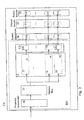
- the electrical baseband signal is then again transformed to a symbol stream, still at the oversampled rate, by means of the matched filter 25 which further delivers the symbols to a second filter Z.
- this second filter consisted of a filter bank with as many individual filters as there are network terminals in the communication system, whereby each filter of the filter bank performs the multiplication of the received signal with the code attributed to the specific network terminal. This operation is followed in CDMA by the undersampling of the digital data stream, performed within module US.
- each filter combined with an undersampling unit thereby retrieves the original data transmitted by the specific network terminal to which it is assigned.
- dispersive channels where this perfect synchronisation is not obtained, the discrimination of the individual network terminal data from the composite signal is not guaranteed.
- the second filter of the receiver at the central station is adapted to perform the z-transform, each time a new oversampled symbol stream arrives at the second filter, on this received oversampled symbol stream. It furthermore has to evaluate this z-transform at the specific zero's that were assigned to the different individual network terminals.
- this second filter Z thereby consists of n individual filter modules for performing the z-transform, whereby n equals the amount of network terminals coupled to the central station.
- Each of these filters Z1 to Zn thereby performs this z-transformation at the specific zero attrituted to the associated network terminal T1 to Tn.
- each filter for instance filter Zi, thereby obtains at its output the original symbol stream that was previously generated by symbol modulation unit 14 of terminal Ti, however at the oversampled rate.
- the rate of this oversampled symbol stream is brought back to its original rate by means of the associated undersampler USi included in oversampler US.
- Next demapping or symbol demodulation, channel and eventual source decoding operations, are performed by respective symbol demodulator 24, channel decoder 23 and source decoder 22.
- the demapper 24 consists of n individual demappers 241 to 24n;
- the channel decoder 23 consists of n individual decoders denoted 231,.., 23i,..., 23n, and source decoder 22 consists of n individual decoders denoted 221,...,22i,...,22n.
- the z-transform of the complete signal arriving at the input of the receiver 24 is the sum of all z-transforms of all contributions of all terminals T1 to Tn because of the linear feature of the z-transform and because of the first order assumption generally accepted in the art that there is no influence of one terminal on the transmission of the others.
- g ⁇ l ( z ) denotes the z-transform of the total of the shaping filter, the individual communications channel Li, the common link and the match filter of any arbitrary terminal Ti. This function may determined by the communications system during for instance a learning phase.
- w ⁇ ( z ) denotes the z-transform of the noise, being a stochastic function of z.
- Z The function of Z is merely to perform this z-transform at the received symbol flow arriving at Z, and to evaluate this in the different zero's .
- a l [ k ] c ⁇ l ( ⁇ l ) g ⁇ l ( ⁇ l ) + w ⁇ ( ⁇ l ) since c ⁇ l ( ⁇ l ) as well as g ⁇ l ( ⁇ l ) are known, and since, at a first approximation, contribution of the noise is assumed to be neglectable, the original value a l [ k ]of the symbol can be recovered within Zi as apparent from (5).
- the unique variable for instance variable ⁇ 1 assigned to a particular network terminal, for instance T1
- a particular network terminal for instance T1
- the all-pass filtering is then performed whereby the original factor z- ⁇ 1 is replaced by the plurality of factors (z- ⁇ 1l) ...(z- ⁇ 1j)...(z- ⁇ 1m).
- the corresponding factor for the poles within this all-pass filter (z- ⁇ 1 -1* ) as well consists of a plurality of factors (z- ⁇ 1l -1* )...(z- ⁇ 1j -1* )...(z- ⁇ 1m -1* ) .
- the individual filter Z1 associated to terminal T1 in its turn consists of a filter bank, one for each of the individual zeroes ⁇ 1l to ⁇ 1m. This technique of course increases the complexity of both transmitter and receiver, especially when all user network terminals are assigned such a plurality of zeroes.
- each of these filters of the filter bank associated to a particular terminal is then followed by an averager, to average the outcome of all of them.
- the thus obtained average signal will have a higher signal to noise ratio than in case there was only one zero attributed to the terminal under consideration. For implementation reasons, typical values of m will not exceed 5. This will already improve the signal to noise ratio with a factor of at most 10Log(5) dB.
- This principle may be further used for compensating for frequency or phase shifts in the upstream channel.
- These frequency shifts can originate from channel impairments such as the Doppler effect, but may also be due to a not perfect matching of the local oscillator in modules 16 and 26 in the transmitter and receiver respectively.
- the plurality of zeroes per terminal can be obtained by distributing them equally on part of the circumference of a circle in the z-plane, for instance a circle with a radius of 2. This part of the contour of this circle is called a phase region per terminal, and it is such that the phase shift between the two end points of this part is larger than or equal to the upper boundary of this frequency shift.
- a characteristic parameter for instance a maximum phase shift between transmitted and received signal of the communication channel between for instance terminal T1 and the central station CS is to be measured by a specific device dedicated to it.
- Such devices are known to a person skilled in the art and range from classical radar to more sophisticated devices using maximum likelihood methods based on the ambiguity function implemented with a DSP.
- this channel parameter C1 such as the upper boundary of the Doppler shift is known for a particular communication channel between a particular network terminal and the central station
- a set of or plurality of unique variable assigned to this particular network terminal are determined from this parameter.
- This set of variables being zeroes for the other all-pass filters in the other network terminals, is then delivered to these network terminals as well as to the receiver of the central station.
- the measurement of the parameter can be performed within the central station, within the terminals themselves, or even distributed.
- the derivation of the plurality of variables from it may as well occur within the central station, or within the terminals. In either case a communication of these values to the relevant devices which need them is to be foreseen.
- a possible way of determining the plurality of these unique variables from the maximum Doppler shift measured consists of distributing them equally on part of the circumference of a circle in the z-plane, for instance a circle with a radius of 2, such that the phase shift between the two end points of this part is larger or equal than the measured Doppler phase shift.
- this technique of multiple variable determination from a measured Doppler shift is applied for all terminals, two phase regions on this circle also have to be separated by at least the maximum Doppler bound measured for all terminals.
- this Doppler shift is measured initially, before the activation of the terminal.
- this parameter is measured at predetermined instances, followed by a regular update and communication to the network terminals and the central station, of the values of these unique variables derived from it. In this way an adaptive multiple access method is obtained, tracking the Doppler shifts, and accordingly adapting the values of the zeroes of the all-pass filters for improving the performance.
- the measurement, determination of the associated plurality of variables, communication to the other terminals and the central station is to be synchronised in order to let the system function properly, especially in the case where updates of the variables have to be determined and provided.
- a person skilled in the art is however capable of realising such synchronisation, which will accordingly not be further described since it is not relevant to the invention itself.
Landscapes
- Engineering & Computer Science (AREA)
- Signal Processing (AREA)
- Computer Networks & Wireless Communication (AREA)
- Mobile Radio Communication Systems (AREA)
- Small-Scale Networks (AREA)
Claims (14)
- Mehrfachzugriffsverfahren zum Einsatz in einem Kommunikations-Netzwerk, in dem eine Zentralstation (CS) mit einer Vielzahl von Netzwerk-Endgeräten (T1, ..., Ti, ..., Tn) auf eine Punkt-zu-Mehrpunkt-Weise über die Reihenschaltung einer gemeinsamen Verbindung (L) und jeweiliger individueller Netzwerk-Endgeräte-Verbindungen (L1, ..., Li, ..., Ln) gekoppelt ist, wobei das Verfahren einen Schritt enthält, eine entsprechende eindeutige Variable (ρ1, ..., ρi, ..., ρn) jedem entsprechenden Netzwerk-Endgerät der Vielzahl (T1, ..., Ti, ..., Tn) zuzuordnen, wobei das Verfahren eine erste Filterungs-Operation mindestens eines überabgetasteten (oversampled) Symbols umfasst, das aus Information in Aufwärtsrichtung abgeleitet wird, die von einem Endgerät (Ti) der Vielzahl zur Zentralstation (CS) zu übertragen ist, wobei das Verfahren einen nächsten Schritt der Filterung eines empfangenen überabgetasteten Symbolstroms an der Zentralstation (CS) umfasst, um die Zentralstation in die Lage zu versetzen, daraus das mindestens eine überabgetastete Symbol abzutrennen, das zuvor von dem Netzwerk-Endgerät (Ti) zur Zentralstation (CS) gesendet wurde,
dadurch gekennzeichnet, dass
die erste Filterungs-Operation eine Allpass-Filterungs-Operation des mindestens einen überabgetasteten Symbols umfasst, wobei die Allpass-Filterungs-Operation eine solche Z-Transformations-Übertragungsfunktion
der nächste Schritt der Filterung darin besteht, die Z-Transformation des empfangenen überabgetasteten Symbolstroms durchzuführen und die Z-Transformierte an der eindeutigen Variable (ρi) zu berechnen, die dem Netzwerk-Endgerät (Ti) zugeordnet ist. - Mehrfachzugriffsverfahren gemäß Anspruch 1,
dadurch gekennzeichnet, dass
mindestens eine entsprechende eindeutige Variable (ρ1), die mindestens einem Netzwerk-Endgerät (T1) der Vielzahl zugeordnet ist, aus einer Vielzahl von eindeutigen Variablen besteht, die dem mindestens einen Netzwerk-Endgerät (T1) zugeordnet sind,
der Nullstellen-Faktor der Z-Transformation der ersten Filterungs-Operation, die in allen anderen Netzwerk-Endgeräten (T2, ..., Tn) durchgeführt wird und die als Nullstelle die mindestens eine entsprechende eindeutige Variable des mindestens einen Netzwerk-Endgerätes (T1) hat, dabei aus einer Vielzahl von Nullstellen-Faktoren mit der Vielzahl eindeutiger Variablen als Nullstellen besteht,
wobei an der Zentralstation die Z-Transformierte bei jeder eindeutigen Variable der Vielzahl, die mindestens einem Netzwerk-Endgerät (T1) zugeordnet ist, berechnet wird. - Mehrfachzugriffsverfahren gemäß Anspruch 2,
dadurch gekennzeichnet, dass
das Verfahren einen zusätzlichen Schritt der Messung eines Kanal-Parameters des Kommunikationskanals zwischen dem mindestens einen Netzwerk-Endgerät (T1) und der Zentralstation (CS) umfasst,
die Vielzahl eindeutiger Variablen, die dem mindestens einen Netzwerk-Endgerät (T1) zugeordnet sind, dabei aus dem Kanal-Parameter abgeleitet wird. - Sender (TXi) zur Verwendung in einem Netzwerk-Endgerät (Ti) einer Vielzahl von Netzwerk-Endgeräten (T1, ..., Ti, ..., Tn), die auf eine Mehrpunkt-zu-Punkt-Weise über die Reihenschaltung jeweiliger individueller Netzwerk-Endgeräte-Verbindungen (L1, ..., Li, ..., Ln) und einer gemeinsamen Verbindung (L) mit einer Zentralstation (CS) eines Kommunikations-Netzwerks gekoppelt sind,
wobei jedem entsprechenden Netzwerk-Endgerät der Vielzahl (T1, ..., Ti, ..., Tn) eine entsprechende eindeutige Variable (ρ1, ..., ρi, ..., ρn) zugeordnet wird,
wobei der Sender (TXi) ein erstes Filter (APFi) enthält, dass so angepasst ist, eine erste Filterungs-Operation mindestens eines überabgetasteten Symbols durchzuführen, das aus Information in Aufwärtsrichtung abgeleitet wird, die von dem Netzwerk-Endgerät (Ti) zu senden ist,
dadurch gekennzeichnet, dass
das erste Filter (APFi) aus einem Allpass-Filter besteht, dessen Nullstellen der Übertragungsfunktion der Z-Transformation aus allen entsprechenden eindeutigen Variablen bestehen, mit Ausnahme der eindeutigen Variable (ρi), die dem Netzwerk-Endgerät (Ti) zugeordnet ist. - Sender (TXi) gemäß Anspruch 4,
dadurch gekennzeichnet, dass
mindestens eine entsprechende eindeutige Variable (ρ1), die mindestens einem anderen Netzwerk-Endgerät (T1) zugeordnet ist, aus einer Vielzahl eindeutiger Variablen besteht, die mindestens einem anderen Netzwerk-Endgerät (T1) zugeordnet sind,
der Nullstellen-Faktor der Z-Transformation des Allpass-Filters des Senders, der in Zusammenhang mit der mindestens einen entsprechenden eindeutigen Variable steht, dabei aus einer Vielzahl von Nullstellen-Faktoren mit der Vielzahl eindeutiger Variablen als Nullstellen besteht. - Empfänger (RX) zur Verwendung in einer Zentralstation (CS), die auf eine Punkt-zu-Mehrpunkt-Weise über die Reihenschaltung einer gemeinsamen Verbindung (L) und jeweiliger individueller Netzwerk-Endgeräte-Verbindungen (L1, ..., Li, ..., Ln) mit einer Vielzahl von Netzwerk-Endgeräten (T1, ..., Ti, ..., Tn) eines Kommunikations-Netzwerks gekoppelt ist,
wobei jedem Netzwerk-Endgerät der Vielzahl (T1, ..., Ti, ..., Tn) eine entsprechende eindeutige Variable (ρ1, ..., ρi, ..., ρn) zugeordnet ist,
wobei der Empfänger (RX) zweite Filter-Mittel (Z) enthält, die so angepasst sind, eine Filterungs-Operation eines empfangenen überabgetasteten Symbolstroms in der Zentralstation (CS) durchzuführen, um die Zentralstation in die Lage zu versetzen, zu unterscheiden, welcher Teil des empfangenen überabgetasteten Symbolstroms zuvor von einem Netzwerk-Endgerät (T1) der Vielzahl (T1, ..., Ti, ..., Tn) gesendet wurde,
dadurch gekennzeichnet, dass
das zweite Filter-Mittel (Z) aus einem Z-Transformations-Mittel besteht, das so angepasst ist, die Z-Transformation des empfangenen überabgetasteten Symbolstroms durchzuführen und die Z-Transformierte der entsprechenden eindeutigen Variablen (ρ1), die dem Netzwerk-Endgerät (T1) zugeordnet ist, zu berechnen. - Empfänger (RX) gemäß Anspruch 6,
dadurch gekennzeichnet, dass
die entsprechende eindeutige Variable (ρ1), die dem Netzwerk-Endgerät (T1) zugeordnet ist, aus einer Vielzahl eindeutiger Variablen besteht, die dem Netzwerk-Endgerät (T1) zugeordnet sind,
wobei das Z-Transformations-Mittel (Z) weiterhin so angepasst ist, die Z-Transformation an jeder eindeutigen Variablen der Vielzahl, die dem Netzwerk-Endgerät (T1) zugeordnet ist, zu berechnen. - Netzwerk-Endgerät (Ti) eines Kommunikations-Netzwerks, in dem eine Zentralstation (CS) mit einer Vielzahl von Netzwerk-Endgeräten (T1, ..., Ti, ..., Tn), die das Netzwerk-Endgerät enthält, auf eine Punkt-zu-Mehrpunkt-Weise über die Reihenschaltung einer gemeinsamen Verbindung (L) und jeweiliger individueller Netzwerk-Endgeräte-Verbindungen (L1, ..., Li, ..., Ln) von der Zentralstation zu der Vielzahl von Netzwerk-Endgeräten gekoppelt ist,
dadurch gekennzeichnet, dass
das Netzwerk-Endgerät (Ti) einen Sender (TXi) gemäß Anspruch 4 oder 5 enthält. - Zentralstation (CS) eines Kommunikations-Netzwerks, in dem die Zentralstation (CS) mit einer Vielzahl von Netzwerk-Endgeräten (T1, ..., Ti, ..., Tn) auf eine Punkt-zu-Mehrpunkt-Weise über die Reihenschaltung einer gemeinsamen Verbindung (L) und jeweiliger individueller Netzwerk-Endgeräte-Verbindungen (L1, ..., Li, ..., Ln) von der Zentralstation zu den Netzwerk-Endgeräten gekoppelt ist,
dadurch gekennzeichnet, dass
die Zentralstation (CS) einen Empfänger (RX) gemäß Anspruch 6 oder 7 enthält. - Kommunikations-Netzwerk, das eine Zentralstation (CS) enthält, die mit einer Vielzahl von Netzwerk-Endgeräten (T1, ..., Ti, ..., Tn), die in dem Kommunikations-Netzwerk enthalten sind, auf eine Punkt-zu-Mehrpunkt-Weise über die Reihenschaltung einer gemeinsamen Verbindung (L) und jeweiliger individueller Netzwerk-Endgeräte-Verbindungen (L1, ..., Li, ..., Ln) gekoppelt ist,
dadurch gekennzeichnet, dass
die Zentralstation (CS) einen Empfänger gemäß Anspruch 6 enthält, und mindestens ein Netzwerk-Endgerät (Ti) einen Sender (Txi) gemäß Anspruch 4 enthält. - Kommunikations-Netzwerk gemäß Anspruch 10,
dadurch gekennzeichnet, dass
der Empfänger (RX) weitere Funktionen aufweist, wie in Anspruch 7 beschrieben, und der Sender (TXi) weitere Funktionen aufweist, wie in Anspruch 5 beschrieben. - Kommunikations-Netzwerk gemäß Anspruch 11,
dadurch gekennzeichnet, dass
das Kommunikations-Netzwerk ein Gerät enthält, das so angepasst ist, einen Kanal-Parameter des Kommunikationskanals zwischen mindestens einem Netzwerk-Endgerät und der Zentralstation (CS) zu messen und daraus die Vielzahl eindeutiger Variablen abzuleiten, die dem mindestens einen Netzwerk-Endgerät zugeordnet sind. - Kommunikations-Netzwerk gemäß Anspruch 12,
dadurch gekennzeichnet, dass
das Gerät weiterhin so angepasst ist, dass es die Vielzahl eindeutiger Variablen, die dem mindestens einen Netzwerk-Endgerät zugeordnet sind, an den Empfänger in der Zentralstation und an die Vielzahl von Netzwerk-Endgeräten liefert. - Kommunikations-Netzwerk gemäß Anspruch 13,
dadurch gekennzeichnet, dass
das Gerät weiterhin so angepasst ist, dass es den mindestens einen Kanal-Parameter an vorher festgelegten Zeitpunkten misst, um daraus aktualisierte Werte der eindeutigen Variablen der Vielzahl zu berechnen und die aktualisierten Werte an den Empfänger und an die Vielzahl von Netzwerk-Endgeräten zu liefern.
Priority Applications (6)
| Application Number | Priority Date | Filing Date | Title |
|---|---|---|---|
| ES99402766T ES2255237T3 (es) | 1999-11-05 | 1999-11-05 | Metodo y aparato para acceso multiple en un sistema de comunicaciones. |
| EP99402766A EP1098468B1 (de) | 1999-11-05 | 1999-11-05 | Verfahren un Vorrichtung für Mehrfachzugriff in einem Kommunikationssystem |
| AT99402766T ATE318031T1 (de) | 1999-11-05 | 1999-11-05 | Verfahren un vorrichtung für mehrfachzugriff in einem kommunikationssystem |
| DE69929871T DE69929871T2 (de) | 1999-11-05 | 1999-11-05 | Verfahren und Vorrichtung für Mehrfachzugriff in einem Kommunikationssystem |
| JP2000311409A JP2001177506A (ja) | 1999-11-05 | 2000-10-12 | 多重アクセス方法、この方法を実行するための装置およびこれらの方法を使用した通信システム |
| US09/704,680 US6744824B1 (en) | 1999-11-05 | 2000-11-03 | Multiple access method, devices for performing this method and communications systems using these methods |
Applications Claiming Priority (1)
| Application Number | Priority Date | Filing Date | Title |
|---|---|---|---|
| EP99402766A EP1098468B1 (de) | 1999-11-05 | 1999-11-05 | Verfahren un Vorrichtung für Mehrfachzugriff in einem Kommunikationssystem |
Publications (2)
| Publication Number | Publication Date |
|---|---|
| EP1098468A1 EP1098468A1 (de) | 2001-05-09 |
| EP1098468B1 true EP1098468B1 (de) | 2006-02-15 |
Family
ID=8242170
Family Applications (1)
| Application Number | Title | Priority Date | Filing Date |
|---|---|---|---|
| EP99402766A Expired - Lifetime EP1098468B1 (de) | 1999-11-05 | 1999-11-05 | Verfahren un Vorrichtung für Mehrfachzugriff in einem Kommunikationssystem |
Country Status (6)
| Country | Link |
|---|---|
| US (1) | US6744824B1 (de) |
| EP (1) | EP1098468B1 (de) |
| JP (1) | JP2001177506A (de) |
| AT (1) | ATE318031T1 (de) |
| DE (1) | DE69929871T2 (de) |
| ES (1) | ES2255237T3 (de) |
Families Citing this family (15)
| Publication number | Priority date | Publication date | Assignee | Title |
|---|---|---|---|---|
| US7173938B1 (en) * | 2001-05-18 | 2007-02-06 | Current Grid, Llc | Method and apparatus for processing outbound data within a powerline based communication system |
| US7194528B1 (en) | 2001-05-18 | 2007-03-20 | Current Grid, Llc | Method and apparatus for processing inbound data within a powerline based communication system |
| US6844809B2 (en) * | 2001-12-04 | 2005-01-18 | Constantine N. Manis | Passive optical network backhaul for powerline communications |
| US20080161720A1 (en) * | 2002-10-07 | 2008-07-03 | Nicoson Zachary R | Registration system |
| US9638770B2 (en) | 2004-05-21 | 2017-05-02 | Devicor Medical Products, Inc. | MRI biopsy apparatus incorporating an imageable penetrating portion |
| US7708751B2 (en) | 2004-05-21 | 2010-05-04 | Ethicon Endo-Surgery, Inc. | MRI biopsy device |
| US8932233B2 (en) | 2004-05-21 | 2015-01-13 | Devicor Medical Products, Inc. | MRI biopsy device |
| WO2006059767A1 (ja) * | 2004-12-03 | 2006-06-08 | Nec Corporation | 混合信号をブラインド分離する方法及び装置並びに混合信号の送信方法及び装置 |
| US20080056338A1 (en) * | 2006-08-28 | 2008-03-06 | David Stanley Yaney | Power Line Communication Device and Method with Frequency Shifted Modem |
| US8808200B2 (en) | 2007-10-01 | 2014-08-19 | Suros Surgical Systems, Inc. | Surgical device and method of using same |
| US8202229B2 (en) | 2007-10-01 | 2012-06-19 | Suros Surgical Systems, Inc. | Surgical device |
| US20090247901A1 (en) * | 2008-03-25 | 2009-10-01 | Brian Zimmer | Latching side removal spacer |
| US20090247900A1 (en) * | 2008-03-25 | 2009-10-01 | Brian Zimmer | Push button adjustable spacer |
| US8043316B2 (en) * | 2008-05-02 | 2011-10-25 | Suros Surgical Systems, Inc. | Adjustable spacer |
| US8989024B2 (en) * | 2012-06-18 | 2015-03-24 | At&T Intellectual Property I, L.P. | Long term evolution network dynamic overload management |
Family Cites Families (9)
| Publication number | Priority date | Publication date | Assignee | Title |
|---|---|---|---|---|
| JPS6259432A (ja) * | 1985-09-10 | 1987-03-16 | Nec Corp | Fdm/tdm相互変換方式 |
| US5099493A (en) * | 1990-08-27 | 1992-03-24 | Zeger-Abrams Incorporated | Multiple signal receiver for direct sequence, code division multiple access, spread spectrum signals |
| US5177768A (en) * | 1991-11-22 | 1993-01-05 | Bell Communications Research, Inc. | Spread-time code division multiple access technique with arbitrary spectral shaping |
| FR2685593B1 (fr) * | 1991-12-20 | 1994-02-11 | France Telecom | Dispositif de demultiplexage en frequence a filtres numeriques. |
| JPH09200165A (ja) * | 1996-01-18 | 1997-07-31 | Daihen Corp | チャンネル分離用フィルタ装置、psk復調装置及びpsk受信装置 |
| JP3848421B2 (ja) * | 1997-01-31 | 2006-11-22 | 秀男 村上 | 離散時間信号に対する多重化装置および多重化システムと、離散時間信号に対する多重化方法 |
| US6285720B1 (en) * | 1999-05-28 | 2001-09-04 | W J Communications, Inc. | Method and apparatus for high data rate wireless communications over wavefield spaces |
| US6218896B1 (en) * | 1999-08-27 | 2001-04-17 | Tachyon, Inc. | Vectored demodulation and frequency estimation apparatus and method |
| US6452982B1 (en) * | 1999-09-10 | 2002-09-17 | Raytheon Company | Method and system for-down-converting a signal |
-
1999
- 1999-11-05 DE DE69929871T patent/DE69929871T2/de not_active Expired - Fee Related
- 1999-11-05 EP EP99402766A patent/EP1098468B1/de not_active Expired - Lifetime
- 1999-11-05 AT AT99402766T patent/ATE318031T1/de not_active IP Right Cessation
- 1999-11-05 ES ES99402766T patent/ES2255237T3/es not_active Expired - Lifetime
-
2000
- 2000-10-12 JP JP2000311409A patent/JP2001177506A/ja not_active Withdrawn
- 2000-11-03 US US09/704,680 patent/US6744824B1/en not_active Expired - Fee Related
Also Published As
| Publication number | Publication date |
|---|---|
| US6744824B1 (en) | 2004-06-01 |
| JP2001177506A (ja) | 2001-06-29 |
| ES2255237T3 (es) | 2006-06-16 |
| EP1098468A1 (de) | 2001-05-09 |
| DE69929871D1 (de) | 2006-04-20 |
| DE69929871T2 (de) | 2006-11-02 |
| ATE318031T1 (de) | 2006-03-15 |
Similar Documents
| Publication | Publication Date | Title |
|---|---|---|
| EP1098468B1 (de) | Verfahren un Vorrichtung für Mehrfachzugriff in einem Kommunikationssystem | |
| US5636246A (en) | Multicarrier transmission system | |
| AU725718B2 (en) | Pulse shaping for multicarrier modulation | |
| EP1303962B1 (de) | Gleitfensterverarbeitung zum empfang von mehrträgersignalen | |
| US5029186A (en) | Method of demodulation in digital communication systems with multipath propagation | |
| US20030026201A1 (en) | Sliding-window transform with integrated windowing | |
| US3524169A (en) | Impulse response correction system | |
| NZ253807A (en) | Estimating received digital symbols using viterbi algorithm | |
| EP0845185B1 (de) | Digitales ubertragungssystem | |
| JPH10190609A (ja) | 直交周波数多重変調信号復調方法 | |
| EP0991237A1 (de) | Mehrträger-Kommunikationsmethode mit zeit- und frequenzdifferentieller Kodierung | |
| EP0220314B1 (de) | Datenübertragungsverfahren mit umkehrbarer energiespreizung | |
| EP3525370B1 (de) | Verfahren und vorrichtung zur auf überlappendem multiplexing basierender decodierung und modulations- und demodulationsverfahren und -system | |
| US3720789A (en) | Electrical signalling systems using correlation detectors | |
| US7072412B1 (en) | Multicarrier digital transmission system using an OQAM transmultiplexer | |
| Tanimoto et al. | Synchronous spread‐spectrum multiplex communication system using a modified m‐sequence | |
| EP1232593A1 (de) | Digitales mehrträger-nachrichtenübertragungs-system | |
| US6381623B1 (en) | Method for adaptive filter adjustment in a QAM/CAP system | |
| Moose | Theory of multi-frequency modulation (MFM) digital communications | |
| Klymash et al. | Increasing the Multi-position Signals Noise Immunity of Mobile Communication Systems Based on High-order Phase Modulation. | |
| JPS639699B2 (de) | ||
| AU708318B2 (en) | Improved multicarrier transmission system | |
| Hilborn | Applications of unsupervised learning to some Problems of digital communications | |
| CN102065051A (zh) | Tds-ofdm系统中pn序列的设计方法及检测前信号的捕获方法 | |
| Clements | The application of iterative techniques to adaptive detection processes |
Legal Events
| Date | Code | Title | Description |
|---|---|---|---|
| PUAI | Public reference made under article 153(3) epc to a published international application that has entered the european phase |
Free format text: ORIGINAL CODE: 0009012 |
|
| AK | Designated contracting states |
Kind code of ref document: A1 Designated state(s): AT BE CH CY DE DK ES FI FR GB GR IE IT LI LU MC NL PT SE |
|
| AX | Request for extension of the european patent |
Free format text: AL;LT;LV;MK;RO;SI |
|
| 17P | Request for examination filed |
Effective date: 20011109 |
|
| AKX | Designation fees paid |
Free format text: AT BE CH CY DE DK ES FI FR GB GR IE IT LI LU MC NL PT SE |
|
| GRAP | Despatch of communication of intention to grant a patent |
Free format text: ORIGINAL CODE: EPIDOSNIGR1 |
|
| GRAS | Grant fee paid |
Free format text: ORIGINAL CODE: EPIDOSNIGR3 |
|
| GRAA | (expected) grant |
Free format text: ORIGINAL CODE: 0009210 |
|
| AK | Designated contracting states |
Kind code of ref document: B1 Designated state(s): AT BE CH CY DE DK ES FI FR GB GR IE IT LI LU MC NL PT SE |
|
| PG25 | Lapsed in a contracting state [announced via postgrant information from national office to epo] |
Ref country code: NL Free format text: LAPSE BECAUSE OF FAILURE TO SUBMIT A TRANSLATION OF THE DESCRIPTION OR TO PAY THE FEE WITHIN THE PRESCRIBED TIME-LIMIT Effective date: 20060215 Ref country code: LI Free format text: LAPSE BECAUSE OF FAILURE TO SUBMIT A TRANSLATION OF THE DESCRIPTION OR TO PAY THE FEE WITHIN THE PRESCRIBED TIME-LIMIT Effective date: 20060215 Ref country code: IT Free format text: LAPSE BECAUSE OF FAILURE TO SUBMIT A TRANSLATION OF THE DESCRIPTION OR TO PAY THE FEE WITHIN THE PRESCRIBED TIME-LIMIT;WARNING: LAPSES OF ITALIAN PATENTS WITH EFFECTIVE DATE BEFORE 2007 MAY HAVE OCCURRED AT ANY TIME BEFORE 2007. THE CORRECT EFFECTIVE DATE MAY BE DIFFERENT FROM THE ONE RECORDED. Effective date: 20060215 Ref country code: FI Free format text: LAPSE BECAUSE OF FAILURE TO SUBMIT A TRANSLATION OF THE DESCRIPTION OR TO PAY THE FEE WITHIN THE PRESCRIBED TIME-LIMIT Effective date: 20060215 Ref country code: CH Free format text: LAPSE BECAUSE OF FAILURE TO SUBMIT A TRANSLATION OF THE DESCRIPTION OR TO PAY THE FEE WITHIN THE PRESCRIBED TIME-LIMIT Effective date: 20060215 Ref country code: BE Free format text: LAPSE BECAUSE OF FAILURE TO SUBMIT A TRANSLATION OF THE DESCRIPTION OR TO PAY THE FEE WITHIN THE PRESCRIBED TIME-LIMIT Effective date: 20060215 Ref country code: AT Free format text: LAPSE BECAUSE OF FAILURE TO SUBMIT A TRANSLATION OF THE DESCRIPTION OR TO PAY THE FEE WITHIN THE PRESCRIBED TIME-LIMIT Effective date: 20060215 |
|
| REG | Reference to a national code |
Ref country code: GB Ref legal event code: FG4D Ref country code: CH Ref legal event code: EP |
|
| REG | Reference to a national code |
Ref country code: IE Ref legal event code: FG4D |
|
| REF | Corresponds to: |
Ref document number: 69929871 Country of ref document: DE Date of ref document: 20060420 Kind code of ref document: P |
|
| PG25 | Lapsed in a contracting state [announced via postgrant information from national office to epo] |
Ref country code: SE Free format text: LAPSE BECAUSE OF FAILURE TO SUBMIT A TRANSLATION OF THE DESCRIPTION OR TO PAY THE FEE WITHIN THE PRESCRIBED TIME-LIMIT Effective date: 20060515 Ref country code: DK Free format text: LAPSE BECAUSE OF FAILURE TO SUBMIT A TRANSLATION OF THE DESCRIPTION OR TO PAY THE FEE WITHIN THE PRESCRIBED TIME-LIMIT Effective date: 20060515 |
|
| REG | Reference to a national code |
Ref country code: ES Ref legal event code: FG2A Ref document number: 2255237 Country of ref document: ES Kind code of ref document: T3 |
|
| PG25 | Lapsed in a contracting state [announced via postgrant information from national office to epo] |
Ref country code: PT Free format text: LAPSE BECAUSE OF FAILURE TO SUBMIT A TRANSLATION OF THE DESCRIPTION OR TO PAY THE FEE WITHIN THE PRESCRIBED TIME-LIMIT Effective date: 20060717 |
|
| NLV1 | Nl: lapsed or annulled due to failure to fulfill the requirements of art. 29p and 29m of the patents act | ||
| REG | Reference to a national code |
Ref country code: CH Ref legal event code: PL |
|
| ET | Fr: translation filed | ||
| PG25 | Lapsed in a contracting state [announced via postgrant information from national office to epo] |
Ref country code: IE Free format text: LAPSE BECAUSE OF NON-PAYMENT OF DUE FEES Effective date: 20061106 |
|
| PG25 | Lapsed in a contracting state [announced via postgrant information from national office to epo] |
Ref country code: MC Free format text: LAPSE BECAUSE OF NON-PAYMENT OF DUE FEES Effective date: 20061130 |
|
| PLBE | No opposition filed within time limit |
Free format text: ORIGINAL CODE: 0009261 |
|
| STAA | Information on the status of an ep patent application or granted ep patent |
Free format text: STATUS: NO OPPOSITION FILED WITHIN TIME LIMIT |
|
| 26N | No opposition filed |
Effective date: 20061116 |
|
| PGFP | Annual fee paid to national office [announced via postgrant information from national office to epo] |
Ref country code: ES Payment date: 20071129 Year of fee payment: 9 Ref country code: DE Payment date: 20071123 Year of fee payment: 9 |
|
| PGFP | Annual fee paid to national office [announced via postgrant information from national office to epo] |
Ref country code: IT Payment date: 20071123 Year of fee payment: 9 |
|
| PG25 | Lapsed in a contracting state [announced via postgrant information from national office to epo] |
Ref country code: GR Free format text: LAPSE BECAUSE OF FAILURE TO SUBMIT A TRANSLATION OF THE DESCRIPTION OR TO PAY THE FEE WITHIN THE PRESCRIBED TIME-LIMIT Effective date: 20060516 |
|
| PGFP | Annual fee paid to national office [announced via postgrant information from national office to epo] |
Ref country code: GB Payment date: 20071120 Year of fee payment: 9 Ref country code: FR Payment date: 20071122 Year of fee payment: 9 |
|
| PG25 | Lapsed in a contracting state [announced via postgrant information from national office to epo] |
Ref country code: LU Free format text: LAPSE BECAUSE OF NON-PAYMENT OF DUE FEES Effective date: 20061105 |
|
| PG25 | Lapsed in a contracting state [announced via postgrant information from national office to epo] |
Ref country code: CY Free format text: LAPSE BECAUSE OF FAILURE TO SUBMIT A TRANSLATION OF THE DESCRIPTION OR TO PAY THE FEE WITHIN THE PRESCRIBED TIME-LIMIT Effective date: 20060215 |
|
| GBPC | Gb: european patent ceased through non-payment of renewal fee |
Effective date: 20081105 |
|
| PG25 | Lapsed in a contracting state [announced via postgrant information from national office to epo] |
Ref country code: IT Free format text: LAPSE BECAUSE OF NON-PAYMENT OF DUE FEES Effective date: 20081105 |
|
| REG | Reference to a national code |
Ref country code: FR Ref legal event code: ST Effective date: 20090731 |
|
| PG25 | Lapsed in a contracting state [announced via postgrant information from national office to epo] |
Ref country code: DE Free format text: LAPSE BECAUSE OF NON-PAYMENT OF DUE FEES Effective date: 20090603 |
|
| PG25 | Lapsed in a contracting state [announced via postgrant information from national office to epo] |
Ref country code: GB Free format text: LAPSE BECAUSE OF NON-PAYMENT OF DUE FEES Effective date: 20081105 |
|
| REG | Reference to a national code |
Ref country code: ES Ref legal event code: FD2A Effective date: 20081106 |
|
| PG25 | Lapsed in a contracting state [announced via postgrant information from national office to epo] |
Ref country code: ES Free format text: LAPSE BECAUSE OF NON-PAYMENT OF DUE FEES Effective date: 20081106 |
|
| PG25 | Lapsed in a contracting state [announced via postgrant information from national office to epo] |
Ref country code: FR Free format text: LAPSE BECAUSE OF NON-PAYMENT OF DUE FEES Effective date: 20081130 |