EP1098130A1 - Object supporting device - Google Patents
Object supporting device Download PDFInfo
- Publication number
- EP1098130A1 EP1098130A1 EP00123787A EP00123787A EP1098130A1 EP 1098130 A1 EP1098130 A1 EP 1098130A1 EP 00123787 A EP00123787 A EP 00123787A EP 00123787 A EP00123787 A EP 00123787A EP 1098130 A1 EP1098130 A1 EP 1098130A1
- Authority
- EP
- European Patent Office
- Prior art keywords
- support column
- carrying device
- support
- supported
- base leg
- Prior art date
- Legal status (The legal status is an assumption and is not a legal conclusion. Google has not performed a legal analysis and makes no representation as to the accuracy of the status listed.)
- Granted
Links
Images


Classifications
-
- A—HUMAN NECESSITIES
- A47—FURNITURE; DOMESTIC ARTICLES OR APPLIANCES; COFFEE MILLS; SPICE MILLS; SUCTION CLEANERS IN GENERAL
- A47B—TABLES; DESKS; OFFICE FURNITURE; CABINETS; DRAWERS; GENERAL DETAILS OF FURNITURE
- A47B49/00—Revolving cabinets or racks; Cabinets or racks with revolving parts
- A47B49/004—Cabinets with compartments provided with trays revolving on a vertical axis
- A47B49/006—Corner cabinets
Definitions
- the invention relates to a carrying device for supporting objects according to the preamble of claim 1.
- a carrying device for supporting objects according to the preamble of claim 1.
- DE-GM 88 11th 656.5 known support device is the support column at the ends of its U-legs firmly connectable to a wall surface and takes with its base leg an invariable position at a distance from the wall surface.
- the invention is concerned with the problem of a support device for support to create objects with little technical effort improves the uses of the supported objects.
- the carrying device according to the invention with its crank-like around a vertical axis rotatable support column can improve access to the Objects can be changed in their position. With eccentric assignment of shelves is at the same time an enlargement of the available Storage space achievable.
- the carrying device according to the invention can in the area via wall brackets the support bearing can be held so that, for example, as functional elements Mirror, cup holder or the like Bath accessories can be fixed to the device and these are to be placed freely rotatable through the wall brackets in the room.
- additional brackets are unnecessary because of the U-legs stored directly on the upper and lower plate parts of the cabinet body can be.
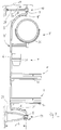
- Fig. 1 is a generally designated 1 support device for support represented by objects, each of which is used as a support and / or functional elements F provided shelves 2 and 3 on the support device 1 are supported.
- the carrying device 1 is U-shaped Support column 4 provided, each starting from a base leg 6 Legs 5 and 5 'for supporting the carrying device 1 in its installed position having.
- the support column 1 is in the embodiment according to the invention at its free ends U-leg 5.5 'by means of external journals 7 and 8 about a vertical axis 9 rotatably mounted.
- the respective upper and lower journals are 7.8 in Bearing assemblies 10,11 added, which in turn on an upper or lower plate part 12, 13 of a cabinet body 14 are supported.
- the shelves 2 and 3 on the base leg 6 firmly supported. It is also conceivable that the parts 2.3 around the The central axis M of the base leg 6 can be rotated (not shown).
- the support column 4 each composed of several parts, for example a welded connection between the base legs 6 and the two Legs 5.5 'can be provided.
- the support column 4 ' is formed as a one-piece molded part, which consists of a Pipe part is bent.
- 6 is a square molded part provided as the support column 4 with end legs 5.5 '. The Machining and adaptation of the square molding to the shelves 2,3 particularly easy.
- FIG. 1 when viewed in conjunction with FIG. 2, illustrates the Formation of the support device 1 in the region of the lower bearing 8 with a Brake 16, which is illustrated in more detail in the bottom view according to FIG. 5.
- the Brake 16 has one that is firmly connected to the bottom-side bearing assembly 11
- Counter member 17 with an elastic trough profile 18, in the a counter member 19 fixed on the underside of the leg 5 'as far as pivotable is that another turn (arrow D) is braked and thus the shelves 2 and 3 with this brake 16 in the to lock the barrier 14 optimal position are fixed (Fig. 1).
- To initiate a rotation D is the Braking resistor in the area of the trough profile 18 by a manual control easy to overcome, for example, on one of the functional elements F.
- the shelves 2 and 3 are for the cabinet body designed as a corner cabinet provided with a tendon-shaped section 20, the braked Position of the device 1 positioned opposite to a cabinet door 21 is that optimal accessibility and usability is achieved. It is also conceivable that the shelves 2,3 with a polygon Circumferential contour or a circular circumferential contour are dimensioned so that in the area of the cabinet door 21 the optimal rotation of the functional elements F is reached.
- FIG 3 and 4 illustrates that for access to the respective shelf 2,3 in the floor area B or B ' the pivoting or rotation of the support device 1 leads to a Partial area 22 'of the railing 22 in the area of the cabinet door 21 from the cabinet body 14 can be swung out, area B can be reached and then through Further movement or pivoting back the carrying device 1 as a whole can be shifted back into the rest position fixed by the brake 16.
- the shelves which have an essentially circular peripheral contour 2,3 are firmly supported on the support column 4, these being the shelves 2,3 eccentrically and thus the available usable area N (Fig. 4) is advantageously enlarged, the shelves 2, 3 have good accessibility and to the objects located on the shelves 2, 3 towards a view that improves their presentation. This is of interest, for example, when the cabinet door 21 is transparent Component consists of glass, for example.
- FIG. 5 is an additional, on the base leg 6 of the Support device 1 supported support plate 23 shown, this support plate 23 in particular as a stabilizing element for an existing wooden Insert shelf 24 is to be placed on the shelf 3 high weight loads to be able to record.
- the shelf 2 points in the illustrated Execution also a support plate 23 'on (Fig. 2).
- Fig. 2 On the support column 4 are 6 respective through holes in the region of the base leg 25,26 (Fig. 2) provided a variable height setting allow the shelves 2,3 by respective connecting elements (not visible). It is also conceivable for the shelves 2, 3 in the connection area to provide the base leg 6 with a clamping device by means of the shelves 2,3 by a stepless height adjustment (not shown) can be determined in largely variable installation positions.
- FIG. 6 is designed as a corner cabinet Cabinet body 14 provided with a cabinet opening 27 which by means of a Area of the support device 1 'supported cabinet door 21' is closable.
- This cabinet door 21 ' is rotated together with the carrying device 1' moved about the vertical axis 9 and can thus advantageously in the interior of the Cabinet body 14 are shifted.
- This is a front room for movement (Similar to Fig. 4) for this door 21 'unnecessary and the usable space in front of the Cabinet body 14 unaffected.
- the cabinet door 21 'by a parallel displacement be shifted towards the vertical axis 9 and for the backward shift is conceivable use a compression spring, not shown.
- the control of, for example on the support column 4 'fixed door 21' can advantageously have a curve control provided in the area of the bottom-side bearing assembly 11 34 (Fig. 6) can be reached, the guide cams 35 a respective opening or close position.
- FIG. 7 illustrates a third embodiment of the carrying device 1 ′′, the bearings 7, 8, the bearing assemblies 10, 11 of the support column 4 upper and a lower wall bracket 28, 29 pivotable on the wall W support, and thus the vertical axis 9 'is formed.
- the collar length L of the wall bracket 28, 29 is greater than the length S of the two free, arc-shaped extending U-leg 5.5 'of the support column 4. This ensures that the support device 1 "in the area of the as a mirror 30, cup holder 31 and shelves 32,33 trained support and functional elements F freely rotatable on the wall W is positioned.
- the functional elements 30 to 32 are fixed with the Support column 4 connected, it is also conceivable that here a pivotable Storage is provided or additional, customer-specific selectable Functional elements F to be fixed on the carrying device 1 ".
Abstract
Description
Die Erfindung betrifft eine Tragvorrichtung zur Abstützung von Gegenständen
gemäß dem Oberbegriff des Anspruchs 1. Bei dieser aus der DE-GM 88 11
656.5 bekannten Tragvorrichtung ist die Tragsäule an den Enden ihrer U-Schenkel
fest mit einer Wandfläche verbindbar und nimmt mit ihrem Basisschenkel
eine unveränderliche Lage im Abstand vor der Wandfläche ein.The invention relates to a carrying device for supporting objects
according to the preamble of
Die Erfindung befaßt sich mit dem Problem, eine Tragvorrichtung zur Abstützung von Gegenständen zu schaffen, die mit geringem technischen Aufwand die Nutzungsmöglichkeiten der abgestützten Gegenstände verbessert.The invention is concerned with the problem of a support device for support to create objects with little technical effort improves the uses of the supported objects.
Die Erfindung löst diese Aufgabe durch eine Tragvorrichtung mit den kennzeichnenden
Merkmalen des Anspruchs 1. Hinsichtlich wesentlicher weiterer
Ausgestaltungsmerkmale wird auf die Ansprüche 2 bis 15 verwiesen.The invention solves this problem by a carrying device with the characteristic
Features of
Die erfindungsgemäße Tragvorrichtung mit ihrer kurbelartig um eine Hochachse drehbaren Tragsäule kann zur Verbesserung der Zugangsmöglichkeiten zu den Gegenständen beliebig in ihrer Lage verändert werden. Bei exzentrischer Zuordnung von Anlageböden ist damit zugleich eine Vergrößerung der verfügbaren Ablagefläche erzielbar.The carrying device according to the invention with its crank-like around a vertical axis rotatable support column can improve access to the Objects can be changed in their position. With eccentric assignment of shelves is at the same time an enlargement of the available Storage space achievable.
Die erfindungsgemäße Tragvorrichtung kann dabei über Wandhalter im Bereich der Stützlager so gehalten sein, daß beispielsweise als Funktionselemente Spiegel, Becherhalter od.dgl. Badzubehör an der Vorrichtung festlegbar und diese weitgehend frei drehbar durch die Wandhalter im Raum zu plazieren sind. Bei einem Einbau der Tragvorrichtung in einen Umbau, beispielsweise in einem Schrankkorpus, sind zusätzliche Halterungen entbehrlich, da die U-Schenkel unmittelbar an oberen und unteren Plattenteilen des Schrankkorpus gelagert werden können.The carrying device according to the invention can in the area via wall brackets the support bearing can be held so that, for example, as functional elements Mirror, cup holder or the like Bath accessories can be fixed to the device and these are to be placed freely rotatable through the wall brackets in the room. When the support device is installed in a conversion, for example in a Cabinet body, additional brackets are unnecessary because of the U-legs stored directly on the upper and lower plate parts of the cabinet body can be.
Weitere Einzelheiten und vorteilhafte Wirkungen der Erfindung ergeben sich aus der nachfolgenden Beschreibung und den Zeichnungen, die mehrere Ausführungsbeispiele der erfindungsgemäßen Tragvorrichtung veranschaulichen. In der Zeichnung zeigen:
- Fig. 1
- eine Perspektivdarstellung der erfindungsgemäßen Tragvorrichtung in einem Schrankkörper,
- Fig. 2
- eine Seitenansicht der Tragvorrichtung gemäß Fig. 1,
- Fig. 3
- eine Draufsicht auf die Tragvorrichtung gemäß Fig. 1,
- Fig. 4
- eine Draufsicht auf die Tragvorrichtung ähnlich Fig. 3 mit in Gebrauchsstellung verlagerten Tragelementen sowie geöffneter Schranktür,
- Fig. 5
- eine Unteransicht der im Schrankkörper befindlichen Tragvorrichtung,
- Fig. 6
- eine Perspektivdarstellung ähnlich Fig. 1 mit der Tragvorrichtung in einer zweiten Ausführungsform in einem Schrankkörper, und
- Fig. 7
- eine Seitenansicht der Tragvorrichtung in einer dritten Ausführungsform mit Wandhaltern.
- Fig. 1
- 2 shows a perspective view of the carrying device according to the invention in a cabinet body,
- Fig. 2
- 2 shows a side view of the carrying device according to FIG. 1,
- Fig. 3
- 2 shows a plan view of the carrying device according to FIG. 1,
- Fig. 4
- 3 shows a top view of the carrying device similar to FIG. 3 with the carrying elements shifted into the use position and the open cabinet door,
- Fig. 5
- a bottom view of the support device located in the cabinet body,
- Fig. 6
- a perspective view similar to FIG. 1 with the support device in a second embodiment in a cabinet body, and
- Fig. 7
- a side view of the support device in a third embodiment with wall brackets.
In Fig. 1 ist eine insgesamt mit 1 bezeichnete Tragvorrichtung zur Abstützung
von Gegenständen dargestellt, wobei zu deren Aufnahme jeweilige als Trag-
und/oder Funktionselemente F vorgesehene Ablageböden 2 und 3 an der Tragvorrichtung
1 abgestützt sind. Die Tragvorrichtung 1 ist mit einer U-förmigen
Tragsäule 4 versehen, die ausgehend von einem Basisschenkel 6 jeweilige
Schenkel 5 und 5' zur Abstützung der Tragvorrichtung 1 in deren Einbaulage
aufweist.In Fig. 1 is a generally designated 1 support device for support
represented by objects, each of which is used as a support
and / or functional elements F provided
Die Tragsäule 1 ist in erfindungsgemäßer Ausführung an ihren freien Enden der
U-Schenkel 5,5' mittels außerseitiger Lagerzapfen 7 und 8 um eine Hochachse
9 drehbar gelagert. In den beiden Ausführungsformen der Tragvorrichtung 1
gemäß Fig. 1 bis 6 sind die jeweiligen oberen und unteren Lagerzapfen 7,8 in
Lagerbaugruppen 10,11 aufgenommen, die ihrerseits an einem oberen bzw.
unteren Plattenteil 12,13 eines Schrankkörpers 14 abgestützt sind. In dieser
Ausführung der Tragvorrichtung 1 sind die Ablageböden 2 und 3 am Basisschenkel
6 fest abgestützt. Ebenfalls denkbar ist, daß die Teile 2,3 um die
Mittelachse M des Basisschenkels 6 drehbar sind (nicht dargestellt).The
In der Ausführungsform der Tragvorrichtung gemäß Fig. 1 bis 5 ist die Tragsäule
4 jeweils aus mehreren Teilen zusammengesetzt, wobei beispielsweise
eine Schweißverbindung zwischen dem Basisschenkeln 6 und den beiden
Schenkeln 5,5' vorgesehen sein kann. In den Ausführungsformen gemäß Fig. 6
und 7 ist die Tragsäule 4' als einstückiges Formteil ausgebildet, das aus einem
Rohrteil gebogen ist. In der Ausführungsform gemäß Fig. 6 ist ein Vierkant-Formteil
als die Tragsäule 4 mit endseitigen Schenkeln 5,5' vorgesehen. Die
Bearbeitung und Anpassung des Vierkant-Formteils an die Ablageböden 2,3 ist
besonders einfach.In the embodiment of the support device according to FIGS. 1 to 5, the
Die Darstellung gemäß Fig. 1 verdeutlicht in Zusammenschau mit Fig. 2 die
Ausbildung der Tragvorrichtung 1 im Bereich des unteren Lagers 8 mit einer
Bremse 16, die in der Unteransicht gemäß Fig. 5 näher veranschaulicht ist. Die
Bremse 16 weist dabei ein mit der bodenseitigen Lagerbaugruppe 11 fest verbundenes
Gegenglied 17 mit einer elastischen Muldenprofilierung 18 auf, in die
ein unterseitig am Schenkel 5' festgelegtes Gegenglied 19 soweit einschwenkbar
ist, daß eine weitere Drehung (Pfeil D) gebremst wird und damit die Ablageböden
2 und 3 mit dieser Bremse 16 in der zum Verschluß des Schrankens
14 optimalen Lage fixiert sind (Fig. 1). Zur Einleitung einer Drehung D ist der
Bremswiderstand im Bereich der Muldenprofilierung 18 durch eine Handbedienung
beispielsweise an einem der Funktionselemente F einfach zu überwinden.The illustration according to FIG. 1, when viewed in conjunction with FIG. 2, illustrates the
Formation of the
Die Ablageböden 2 und 3 sind für den als Eckschrank ausgebildeten Schrankkkörper
mit einem sehnenförmigen Abschnitt 20 versehen, der in gebremster
Stellung der Vorrichtung 1 in Gegenüberlage zu einer Schranktür 21 so positioniert
ist, daß eine optimale Zugänglichkeit und Bedienbarkeit erreicht ist.
Ebenso ist denkbar, daß die Ablageböden 2,3 mit einer ein Vieleck bildenden
Umfangskontur oder einer kreisförmigen Umfangskontur so bemessen sind,
daß im Bereich der Schranktür 21 die optimale Drehung der Funktionselemente
F erreicht ist. In der Draufsicht gemäß Fig. 3 und Fig. 4 ist veranschaulicht , daß
für einen Zugriff auf den jeweiligen Ablageboden 2,3 im Bodenbereich B bzw. B'
die Verschwenkung bzw. Drehung der Tragvorrichtung 1 dazu führt, daß ein
Teilbereich 22' der Reling 22 im Bereich der Schranktür 21 aus dem Schrankkörper
14 herausschwenkbar ist, der Bereich B erreichbar ist und danach durch
Weiterbewegung oder Rückschwenkung die Tragvorrichtung 1 insgesamt
wieder in die durch die Bremse 16 fixierte Ruhestellung verlagerbar ist.The
Die eine im wesentlichen kreisförmige Umfangskontur aufweisenden Ablageböden
2,3 sind an der Tragsäule 4 fest abgestützt, wobei diese die Ablageböden
2,3 exzentrisch durchsetzt und damit die verfügbare Nutzfläche N (Fig.
4) vorteilhaft vergrößert ist, die Ablageböden 2,3 eine gute Zugänglichkeit aufweisen
und zu den jeweils auf den Ablageböden 2,3 befindlichen Gegenständen
hin eine deren Präsentation verbessernde Sicht erreicht ist. Dies ist
beispielsweise dann von Interesse, wenn die Schranktür 21 als durchsichtiges
Bauteil beispielsweise aus Glas besteht.The shelves which have an essentially circular
In der Unteransicht gemäß Fig. 5 ist eine zusätzliche, am Basisschenkel 6 der
Tragvorrichtung 1 abgestützte Stützplatte 23 dargestellt, wobei diese Stützplatte
23 insbesondere als Stabilisierungselement für einen aus Holz bestehenden
Einlageboden 24 einzusetzen ist, um auf dem Ablageboden 3 hohe Gewichtsbelastungen
aufnehmen zu können. Der Ablageboden 2 weist in der dargestellten
Ausführung ebenfalls eine Stützplatte 23' auf (Fig. 2).5 is an additional, on the
An der Tragsäule 4 sind im Bereich des Basisschenkels 6 jeweilige Durchgangsbohrungen
25,26 (Fig. 2) vorgesehen, die eine höhenvariable Festlegung
der Ablageböden 2,3 durch jeweilige Verbindungselemente (nicht sichtbar) ermöglichen.
Ebenso ist denkbar, die Ablageböden 2,3 im Verbindungsbereich
zum Basisschenkel 6 hin mit einer Klemmvorrichtung zu versehen, mittels der
die Ablageböden 2,3 durch eine stufenlose Höhenverstellung (nicht dargestellt)
in weitgehend variablen Einbaulagen festlegbar sind.On the
In der Ausführungsform gemäß Fig. 6 ist der als Eckschrank ausgebildete
Schrankkörper 14 mit einer Schranköffnung 27 versehen, die mittels einer im
Bereich der Tragvorrichtung 1' abgestützten Schranktür 21' verschließbar ist.
Diese Schranktür 21' wird gemeinsam mit der Tragvorrichtung 1' bei deren Drehung
um die Hochachse 9 bewegt und kann damit vorteilhaft im Innenraum des
Schrankkörpers 14 verlagert werden. Damit ist ein vorderer Bewegungsraum
(ähnlich Fig. 4) für diese Tür 21' entbehrlich und der Nutzraum vor dem
Schrankkörper 14 unbeeinflußt. Aus ihrer Schließstellung im Bereich der
Schranköffnung 27 kann die Schranktür 21' durch eine parallele Verschiebung
zur Hochachse 9 hin verlagert werden und für die Rückverlagerung ist denkbar,
eine nicht näher dargestellte Druckfeder einzusetzen. Die Steuerung der beispielsweise
an der Tragsäule 4' festgelegten Tür 21' kann vorteilhaft über eine
im Bereich der bodenseitigen Lagerbaugruppe 11 vorgesehene Kurvensteuerung
34 (Fig. 6) erreicht werden, deren Führungsnocken 35 eine jeweilge Öffnungs-
oder Schließstellung bewirken.6 is designed as a corner
In Fig. 7 ist eine dritte Ausführungsform der Tragvorrichtung 1" veranschaulicht,
wobei die Lager 7,8 deren Lagerbaugruppen 10,11 die Tragsäule 4 an einem
oberen und einem unteren Wandhalter 28,29 schwenkbar an der Wandung W
abstützen, und damit die Hochachse 9' gebildet ist. Die Kraglänge L der Wandhalter
28,29 ist dabei größer als die Länge S der beiden freien, bogenförmig
verlaufenden U-Schenkel 5,5' der Tragsäule 4. Damit ist erreicht, daß die Tragvorrichtung
1" im Bereich der als Spiegel 30, Becherhalter 31 und Ablageböden
32,33 ausgebildeten Trag-und Funktionselemente F frei drehbar an der Wandung
W positioniert ist. Die Funktionselemente 30 bis 32 sind dabei fest mit der
Tragsäule 4 verbunden, wobei ebenso denkbar ist, daß hier eine schwenkbare
Lagerung vorgesehen wird oder zusätzliche, kundenspezifisch auswählbare
Funktionselemente F an der Tragvorrichtung 1" festgelegt werden.7 illustrates a third embodiment of the carrying
Claims (15)
Applications Claiming Priority (2)
| Application Number | Priority Date | Filing Date | Title |
|---|---|---|---|
| DE29919619U DE29919619U1 (en) | 1999-11-08 | 1999-11-08 | Carrying device for supporting objects |
| DE29919619U | 1999-11-08 |
Publications (2)
| Publication Number | Publication Date |
|---|---|
| EP1098130A1 true EP1098130A1 (en) | 2001-05-09 |
| EP1098130B1 EP1098130B1 (en) | 2006-06-07 |
Family
ID=8081336
Family Applications (1)
| Application Number | Title | Priority Date | Filing Date |
|---|---|---|---|
| EP20000123787 Expired - Lifetime EP1098130B1 (en) | 1999-11-08 | 2000-11-02 | Object supporting device |
Country Status (2)
| Country | Link |
|---|---|
| EP (1) | EP1098130B1 (en) |
| DE (2) | DE29919619U1 (en) |
Cited By (1)
| Publication number | Priority date | Publication date | Assignee | Title |
|---|---|---|---|---|
| WO2012052113A1 (en) * | 2010-10-18 | 2012-04-26 | Kesseböhmer Holding OHG | Fitting for furniture |
Families Citing this family (6)
| Publication number | Priority date | Publication date | Assignee | Title |
|---|---|---|---|---|
| DE29919619U1 (en) * | 1999-11-08 | 2000-01-05 | Kesseboehmer Kg | Carrying device for supporting objects |
| DE20002313U1 (en) | 2000-02-10 | 2001-06-13 | Ninkaplast Gmbh | Corner cabinet door fitting |
| DE20010807U1 (en) * | 2000-06-17 | 2000-08-24 | Hettich Hetal Werke | Carousel device for a corner cabinet |
| FR2812177B1 (en) * | 2000-07-26 | 2003-05-16 | Rennaise Du Meuble Soc | STORAGE CABINET HAVING A ROTATING CAROUSEL |
| DE202005005888U1 (en) | 2005-04-13 | 2006-08-17 | Heinrich J. Kesseböhmer KG | Corner cupboard, especially kitchen corner cupboard |
| EP2250938B1 (en) | 2009-05-11 | 2011-09-28 | Vauth-Sagel Holding GmbH & Co. KG | Rotating fitting for a corner cupboard |
Citations (6)
| Publication number | Priority date | Publication date | Assignee | Title |
|---|---|---|---|---|
| DE3100819A1 (en) * | 1981-01-14 | 1982-07-29 | Drägerwerk AG, 2400 Lübeck | Ceiling rotating support for holding medical apparatus, whose position can be fixed, and the connections of power-supply and gas-supply lines in the clinical field |
| DE8811656U1 (en) | 1987-09-18 | 1988-10-27 | Rodet-Loisirs S.A., Saint Rambert D'albon, Fr | |
| US5279429A (en) * | 1990-01-22 | 1994-01-18 | Vauth-Sagel Gmbh & Co. | Pivoting tray with pivot bearing for corner cupboards |
| US5284255A (en) * | 1991-08-09 | 1994-02-08 | Hill-Rom Company, Inc. | Pivoted power column |
| DE29919619U1 (en) * | 1999-11-08 | 2000-01-05 | Kesseboehmer Kg | Carrying device for supporting objects |
| DE20014540U1 (en) * | 2000-08-23 | 2000-10-19 | Kesseboehmer Kg | Fitting to support a corner cupboard door |
-
1999
- 1999-11-08 DE DE29919619U patent/DE29919619U1/en not_active Expired - Lifetime
-
2000
- 2000-11-02 EP EP20000123787 patent/EP1098130B1/en not_active Expired - Lifetime
- 2000-11-02 DE DE50012903T patent/DE50012903D1/en not_active Expired - Lifetime
Patent Citations (7)
| Publication number | Priority date | Publication date | Assignee | Title |
|---|---|---|---|---|
| DE3100819A1 (en) * | 1981-01-14 | 1982-07-29 | Drägerwerk AG, 2400 Lübeck | Ceiling rotating support for holding medical apparatus, whose position can be fixed, and the connections of power-supply and gas-supply lines in the clinical field |
| DE8811656U1 (en) | 1987-09-18 | 1988-10-27 | Rodet-Loisirs S.A., Saint Rambert D'albon, Fr | |
| FR2620780A1 (en) * | 1987-09-18 | 1989-03-24 | Roddt Sa Ets H | Support bar for various accessories |
| US5279429A (en) * | 1990-01-22 | 1994-01-18 | Vauth-Sagel Gmbh & Co. | Pivoting tray with pivot bearing for corner cupboards |
| US5284255A (en) * | 1991-08-09 | 1994-02-08 | Hill-Rom Company, Inc. | Pivoted power column |
| DE29919619U1 (en) * | 1999-11-08 | 2000-01-05 | Kesseboehmer Kg | Carrying device for supporting objects |
| DE20014540U1 (en) * | 2000-08-23 | 2000-10-19 | Kesseboehmer Kg | Fitting to support a corner cupboard door |
Cited By (3)
| Publication number | Priority date | Publication date | Assignee | Title |
|---|---|---|---|---|
| WO2012052113A1 (en) * | 2010-10-18 | 2012-04-26 | Kesseböhmer Holding OHG | Fitting for furniture |
| US9103362B2 (en) | 2010-10-18 | 2015-08-11 | Kesseböhmer Holding e.K. | Fitting for furniture |
| RU2567225C2 (en) * | 2010-10-18 | 2015-11-10 | Кессебёмер Холдинг Э.К. | Fittings for furniture |
Also Published As
| Publication number | Publication date |
|---|---|
| DE50012903D1 (en) | 2006-07-20 |
| DE29919619U1 (en) | 2000-01-05 |
| EP1098130B1 (en) | 2006-06-07 |
Similar Documents
| Publication | Publication Date | Title |
|---|---|---|
| DE10216769A1 (en) | Method for supporting shelf in domestic refrigerator or freezer has support elements slideably attached to vertical rails on sides of appliance | |
| DE4028452A1 (en) | TABLE BASE FOR A WORK OR OFFICE TABLE | |
| DE20321573U1 (en) | Crockery basket with height-adjustable shelves | |
| DE3744363C2 (en) | ||
| EP1098130A1 (en) | Object supporting device | |
| EP2983553B1 (en) | Pull-out device for cupboard pull-out parts | |
| EP1712153B1 (en) | Corner cabinet with carousel, in particular for a kitchen | |
| DE4237738A1 (en) | Wall bar for showers | |
| WO2009007304A1 (en) | Dishwasher basket with foldable rack | |
| DE2934261A1 (en) | Concealed fixing for wall cabinets - allows vertical and wall spacing adjustment through clamping screw or similar fastening device | |
| DE10357331B4 (en) | Support arm for storage devices | |
| DE202013006958U1 (en) | Device for presenting goods | |
| EP1334674B1 (en) | A piece of kitchen furniture, in particuar a suspended cabinet | |
| DE2934260C2 (en) | ||
| DE10148781C1 (en) | Microscope support for a microscope comprises a base plate and a support plate rotatably connected together on their sides facing away from the user | |
| EP1704806B1 (en) | Toilet seat elevating device | |
| EP0024646B1 (en) | Beach chair | |
| EP0030036A2 (en) | Additional furniture for bath tubs | |
| DE3415850A1 (en) | Support base for a monitor, eg. a television set | |
| DE102004038059A1 (en) | Center console for vehicle e.g. passenger car, has vertical toothed racks that couple with catch and release lever that moves catch to release it from racks for vertical adjustment of arm rest | |
| DE102006051181A1 (en) | Height-adjustable table with tripod legs has adjustable top swivel fitting with spindle drive adjustment | |
| DE20318368U1 (en) | Suspension for cable channel or similar on table frame and/or board has pivot bearing for pivoting cable channel about pivot axis between end position and folded down cable channel fitting position | |
| DE4106141A1 (en) | Office cabinet for computer devices and drawers - has height adjustable upper supporting or writing surface enabling integration into existing office | |
| DE2434863A1 (en) | Furniture hinge with height and sideways adjustment - has two eccentric adjusting screws and edge extension for sideways adjustment | |
| DE6940807U (en) | WINDOW THAT'S LEAF HAS A SHELF. |
Legal Events
| Date | Code | Title | Description |
|---|---|---|---|
| PUAI | Public reference made under article 153(3) epc to a published international application that has entered the european phase |
Free format text: ORIGINAL CODE: 0009012 |
|
| AK | Designated contracting states |
Kind code of ref document: A1 Designated state(s): DE |
|
| AX | Request for extension of the european patent |
Free format text: AL;LT;LV;MK;RO;SI |
|
| 17P | Request for examination filed |
Effective date: 20011102 |
|
| AKX | Designation fees paid |
Free format text: AT |
|
| RBV | Designated contracting states (corrected) |
Designated state(s): DE |
|
| REG | Reference to a national code |
Ref country code: DE Ref legal event code: 8566 |
|
| 17Q | First examination report despatched |
Effective date: 20041111 |
|
| GRAP | Despatch of communication of intention to grant a patent |
Free format text: ORIGINAL CODE: EPIDOSNIGR1 |
|
| GRAS | Grant fee paid |
Free format text: ORIGINAL CODE: EPIDOSNIGR3 |
|
| GRAA | (expected) grant |
Free format text: ORIGINAL CODE: 0009210 |
|
| AK | Designated contracting states |
Kind code of ref document: B1 Designated state(s): DE |
|
| REF | Corresponds to: |
Ref document number: 50012903 Country of ref document: DE Date of ref document: 20060720 Kind code of ref document: P |
|
| PLBE | No opposition filed within time limit |
Free format text: ORIGINAL CODE: 0009261 |
|
| STAA | Information on the status of an ep patent application or granted ep patent |
Free format text: STATUS: NO OPPOSITION FILED WITHIN TIME LIMIT |
|
| 26N | No opposition filed |
Effective date: 20070308 |
|
| REG | Reference to a national code |
Ref country code: DE Ref legal event code: R081 Ref document number: 50012903 Country of ref document: DE Owner name: KESSEBOEHMER HOLDING E.K., DE Free format text: FORMER OWNER: HEINRICH J. KESSEBOEHMER KG, 49152 BAD ESSEN, DE Effective date: 20120516 Ref country code: DE Ref legal event code: R082 Ref document number: 50012903 Country of ref document: DE Representative=s name: BUSSE & BUSSE PATENT- UND RECHTSANWAELTE PARTN, DE Effective date: 20120516 Ref country code: DE Ref legal event code: R081 Ref document number: 50012903 Country of ref document: DE Owner name: KESSEBOEHMER HOLDING KG, DE Free format text: FORMER OWNER: HEINRICH J. KESSEBOEHMER KG, 49152 BAD ESSEN, DE Effective date: 20120516 |
|
| REG | Reference to a national code |
Ref country code: DE Ref legal event code: R082 Ref document number: 50012903 Country of ref document: DE Representative=s name: BUSSE & BUSSE PATENT- UND RECHTSANWAELTE PARTN, DE Ref country code: DE Ref legal event code: R081 Ref document number: 50012903 Country of ref document: DE Owner name: KESSEBOEHMER HOLDING KG, DE Free format text: FORMER OWNER: KESSEBOEHMER HOLDING E.K., 49152 BAD ESSEN, DE |
|
| PGFP | Annual fee paid to national office [announced via postgrant information from national office to epo] |
Ref country code: DE Payment date: 20190822 Year of fee payment: 20 |
|
| REG | Reference to a national code |
Ref country code: DE Ref legal event code: R071 Ref document number: 50012903 Country of ref document: DE |