EP1097857A2 - Rear floor structure for vehicles - Google Patents
Rear floor structure for vehicles Download PDFInfo
- Publication number
- EP1097857A2 EP1097857A2 EP00309296A EP00309296A EP1097857A2 EP 1097857 A2 EP1097857 A2 EP 1097857A2 EP 00309296 A EP00309296 A EP 00309296A EP 00309296 A EP00309296 A EP 00309296A EP 1097857 A2 EP1097857 A2 EP 1097857A2
- Authority
- EP
- European Patent Office
- Prior art keywords
- rear floor
- vehicle body
- cross member
- locking metal
- recessed part
- Prior art date
- Legal status (The legal status is an assumption and is not a legal conclusion. Google has not performed a legal analysis and makes no representation as to the accuracy of the status listed.)
- Granted
Links
- 239000002184 metal Substances 0.000 claims abstract description 29
- 239000000725 suspension Substances 0.000 description 2
- 230000000903 blocking effect Effects 0.000 description 1
- 230000008878 coupling Effects 0.000 description 1
- 238000010168 coupling process Methods 0.000 description 1
- 238000005859 coupling reaction Methods 0.000 description 1
- 230000002787 reinforcement Effects 0.000 description 1
- 238000003466 welding Methods 0.000 description 1
Images


Classifications
-
- B—PERFORMING OPERATIONS; TRANSPORTING
- B62—LAND VEHICLES FOR TRAVELLING OTHERWISE THAN ON RAILS
- B62D—MOTOR VEHICLES; TRAILERS
- B62D25/00—Superstructure or monocoque structure sub-units; Parts or details thereof not otherwise provided for
- B62D25/20—Floors or bottom sub-units
-
- B—PERFORMING OPERATIONS; TRANSPORTING
- B60—VEHICLES IN GENERAL
- B60N—SEATS SPECIALLY ADAPTED FOR VEHICLES; VEHICLE PASSENGER ACCOMMODATION NOT OTHERWISE PROVIDED FOR
- B60N2/00—Seats specially adapted for vehicles; Arrangement or mounting of seats in vehicles
- B60N2/24—Seats specially adapted for vehicles; Arrangement or mounting of seats in vehicles for particular purposes or particular vehicles
- B60N2/32—Seats specially adapted for vehicles; Arrangement or mounting of seats in vehicles for particular purposes or particular vehicles convertible for other use
- B60N2/36—Seats specially adapted for vehicles; Arrangement or mounting of seats in vehicles for particular purposes or particular vehicles convertible for other use into a loading platform
-
- B—PERFORMING OPERATIONS; TRANSPORTING
- B60—VEHICLES IN GENERAL
- B60N—SEATS SPECIALLY ADAPTED FOR VEHICLES; VEHICLE PASSENGER ACCOMMODATION NOT OTHERWISE PROVIDED FOR
- B60N2/00—Seats specially adapted for vehicles; Arrangement or mounting of seats in vehicles
- B60N2/24—Seats specially adapted for vehicles; Arrangement or mounting of seats in vehicles for particular purposes or particular vehicles
- B60N2/26—Seats specially adapted for vehicles; Arrangement or mounting of seats in vehicles for particular purposes or particular vehicles for children
- B60N2/28—Seats readily mountable on, and dismountable from, existing seats or other parts of the vehicle
- B60N2/2839—Seats readily mountable on, and dismountable from, existing seats or other parts of the vehicle having a front guard or barrier
-
- B—PERFORMING OPERATIONS; TRANSPORTING
- B60—VEHICLES IN GENERAL
- B60N—SEATS SPECIALLY ADAPTED FOR VEHICLES; VEHICLE PASSENGER ACCOMMODATION NOT OTHERWISE PROVIDED FOR
- B60N2/00—Seats specially adapted for vehicles; Arrangement or mounting of seats in vehicles
- B60N2/24—Seats specially adapted for vehicles; Arrangement or mounting of seats in vehicles for particular purposes or particular vehicles
- B60N2/26—Seats specially adapted for vehicles; Arrangement or mounting of seats in vehicles for particular purposes or particular vehicles for children
- B60N2/28—Seats readily mountable on, and dismountable from, existing seats or other parts of the vehicle
- B60N2/2857—Seats readily mountable on, and dismountable from, existing seats or other parts of the vehicle characterised by the peculiar orientation of the child
- B60N2/286—Seats readily mountable on, and dismountable from, existing seats or other parts of the vehicle characterised by the peculiar orientation of the child forward facing
-
- B—PERFORMING OPERATIONS; TRANSPORTING
- B60—VEHICLES IN GENERAL
- B60N—SEATS SPECIALLY ADAPTED FOR VEHICLES; VEHICLE PASSENGER ACCOMMODATION NOT OTHERWISE PROVIDED FOR
- B60N2/00—Seats specially adapted for vehicles; Arrangement or mounting of seats in vehicles
- B60N2/24—Seats specially adapted for vehicles; Arrangement or mounting of seats in vehicles for particular purposes or particular vehicles
- B60N2/26—Seats specially adapted for vehicles; Arrangement or mounting of seats in vehicles for particular purposes or particular vehicles for children
- B60N2/28—Seats readily mountable on, and dismountable from, existing seats or other parts of the vehicle
- B60N2/2887—Fixation to a transversal anchorage bar, e.g. isofix
- B60N2/289—Fixation to a transversal anchorage bar, e.g. isofix coupled to the vehicle frame
-
- B—PERFORMING OPERATIONS; TRANSPORTING
- B60—VEHICLES IN GENERAL
- B60N—SEATS SPECIALLY ADAPTED FOR VEHICLES; VEHICLE PASSENGER ACCOMMODATION NOT OTHERWISE PROVIDED FOR
- B60N2/00—Seats specially adapted for vehicles; Arrangement or mounting of seats in vehicles
- B60N2/24—Seats specially adapted for vehicles; Arrangement or mounting of seats in vehicles for particular purposes or particular vehicles
- B60N2/30—Non-dismountable or dismountable seats storable in a non-use position, e.g. foldable spare seats
- B60N2/3002—Non-dismountable or dismountable seats storable in a non-use position, e.g. foldable spare seats back-rest movements
- B60N2/3004—Non-dismountable or dismountable seats storable in a non-use position, e.g. foldable spare seats back-rest movements by rotation only
- B60N2/3009—Non-dismountable or dismountable seats storable in a non-use position, e.g. foldable spare seats back-rest movements by rotation only about transversal axis
- B60N2/3013—Non-dismountable or dismountable seats storable in a non-use position, e.g. foldable spare seats back-rest movements by rotation only about transversal axis the back-rest being hinged on the vehicle frame
-
- B—PERFORMING OPERATIONS; TRANSPORTING
- B62—LAND VEHICLES FOR TRAVELLING OTHERWISE THAN ON RAILS
- B62D—MOTOR VEHICLES; TRAILERS
- B62D25/00—Superstructure or monocoque structure sub-units; Parts or details thereof not otherwise provided for
- B62D25/08—Front or rear portions
Definitions
- the present invention relates to a rear floor structure for a vehicle, and particularly to a rear floor structure which is constructed suitably for attaching a locking metal member thereto for securing a child safety seat or the like to the vehicle body.
- a rear floor panel 11 has raised parts 12 on either side thereof in which a rear suspension mechanism is to be disposed and a recessed space 13 between these raised parts 12 for accommodating a spare tire 14.
- FIG 5(a) illustrates a mounting structure of a child safety seat on a seat of a vehicle according to ISO standards, in which a child safety seat 23 is arranged upon a seat 21 of a vehicular seat assembly 20, and secured to the vehicular seat assembly 20 at the rear end of the seat 21 and at the lower end of a seat back 22.
- a locking metal member 17 consisting of a rod that is bent to have a hat-like cross section is fixed on the vehicle side.
- the child safety seat 23 is equipped with a connector 25 that can be pulled out from the bottom, rear end thereof, so that the child safety seat 23 can be latchably secured to the vehicle body by inserting the locking metal member 17 into a locking groove 26 formed at the distal end of the connector 25.
- the locking metal members 17 are provided in two pairs on both sides of the rear floor panel 11 as shown in Figure 3. As can be seen from Figure 3 and Figure 4, the outer pair of locking metal members 17a is welded at their bases onto the top face at the front end of the raised parts 12, while the inner pair of locking metal members 17b is welded at their bases to the front end face 13a of the recessed space 13.
- the locking metal members 17a, 17b are extended upwards from their attachment bases for a rather long distance in order that their distal ends are located at predetermined positions.
- the attachment bases of the locking metal members 17 thus need to have high rigidity in order to ensure certain strength thereof, for which the thickness of the floor panel must be increased at the portions of these attachment bases, or additional brackets or the like must be attached for reinforcement.
- the above described conventional structure has several drawbacks in terms of cost, and the same applies to the mounting structure of the rear seat back centre hinge 18.
- base brackets that connect each pair of the locking metal members may be required, or, because the outer pair and inner pair of locking metal members 17 are welded to the vehicle body at different locations and in different states, complex jigs or tools are required when mounting these onto the vehicle body. Thus the cost for components and mounting operations is high.
- the present invention was devised in view of the above described problems in the prior art, its object being to provide a rear floor structure of a vehicle body, to which locking metal members for mounting a child safety seat or a rear seat back centre hinge can be attached at low cost while ensuring necessary rigidity thereof.
- the present invention provides a rear floor structure of a vehicle body, in which a rear floor cross member that extends in a transverse direction of the vehicle body above a rear floor panel, and one or both of a locking metal member for securing a child safety seat and a rear seat back centre hinge is/are attached to the rear floor cross member.
- Locking metal members are all mounted on a single cross member, and therefore, can be attached to the vehicle body at low cost with high operability and precision, without requiring any additional base brackets or complex tools. Even when a plurality of pairs of locking metal members are attached to the vehicle body, since they are all of a same shape, the cost for fabricating these components can be remarkably reduced. Furthermore, the locking metal members are given high rigidity since the distance between the attachment base and the distal end of the locking metal member is made short.
- the rear seat back centre hinge too, can have high support rigidity because it is attached on the cross member above the rear floor panel and its height is reduced, while the overall cost for attaching it to the vehicle body can be reduced.
- the rear floor cross member can further be used according to needs, for example, for attaching a belt anchor for a seat belt, so that an additional anchor mount can be dispensed with, and the cost further reduced.
- the rear floor structure of the present invention can favourably be applied to a vehicle body in which the rear floor has raised parts on either side thereof and a recessed part between the raised parts for providing a storage space, such that the rear floor cross member bridges the recessed part transversely in a front end portion thereof. That way, the safety feature of the vehicle can be enhanced because the cross member serves as a stopper bar for blocking a stored object such as a spare tire accommodated in the recessed space in the event that the vehicle receives an impact from the rear end.
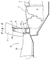
- Reference numeral 1 in the drawings represents a rear floor panel.
- a rear seat cushion 10 of a rear seat assembly 12 In the front end part upon this rear floor panel 1 is disposed a rear seat cushion 10 of a rear seat assembly 12.
- raised parts 2 are formed on either side thereof that protrude upwards for providing a rear suspension mechanism.
- a recessed part 3 is formed between these raised parts 2, which is utilised as a storage space for accommodating a spare tire 4 or the like.
- Tire houses 5 for accommodating rear wheels are welded to the rear floor panel at the outer edges of the raised parts 2, as shown by phantom lines in Figure 1.
- a rear floor cross member 6 consisting of a hollow bar having a square cross section is disposed at a front end portion of the recessed part 3 such as to bridge across the recessed part 3 in a transverse direction of the vehicle body.
- the either end of the rear floor cross member 6 is connected to side wall members such as rear side panels (not shown) of the vehicle body.
- Two pairs of locking metal members 7 for securing a child safety seat such as the one shown in Figure 5(a) and a rear seat back centre hinge 8 are attached on the top face of the rear floor cross member 6.
- the rear seat back centre hinge 8 pivotally supports a central portion of a rear seat back 11 of the rear seat assembly 12, so that the rear seat back 11 can be rotated between an upright seating state shown in Figure 2 and a flat position laid upon the rear seat cushion 10.
- the locking metal member 7 consists of a rod that is bent to have a square U-shaped portion 7a having its open end downwards and a pair of attachment legs 7b extending backwards from the either lower end of the U-shaped portion 7a, and is attached onto the rear floor cross member 6 by welding the attachment legs 7b to the top surface of the rear floor cross member 6.
- the rear seat back centre hinge 8 is also welded at its lower end onto the top surface of the rear floor cross member 6, and is connected to the rear seat back 11 at the upper end thereof through a coupling bracket 9 that is rotatably supported on a pivot 9a.
- the locking metal members 7 can be mounted at predetermined positions at certain pitch spaces highly precisely with high operability without requiring any base brackets for positioning the locking metal members or specific tools, and thus at low cost. Since all of the locking metal members 7 to be attached can be made of a same shape, the cost for fabricating these components can be remarkably reduced. Moreover, because the locking metal members 7 are attached upon the rear floor cross member 6, the distance from the attachment legs 7 to the upper end of the U-shaped portion 7a can be made short; hence high mounting rigidity.
- the rear floor cross member 6 is disposed on the front end side of the recessed part 3 to bridge above the recessed part 3, the rear floor cross member 6 can serve as a stopper bar to block the spare tyre 4 accommodated in the recessed part 3 in the event that the vehicle is bumped from backside, and thus the safety feature of the vehicle is improved.
- the either end of the rear floor cross member 6 is connected to the side walls of the vehicle body, not only the support rigidity of the locking metal members 7 and the rear seat back centre hinge 8, but also the strength and rigidity in the widthways direction of the vehicle body can be enhanced thanks to the rear floor cross member 6.
Landscapes
- Engineering & Computer Science (AREA)
- Transportation (AREA)
- Mechanical Engineering (AREA)
- Aviation & Aerospace Engineering (AREA)
- Health & Medical Sciences (AREA)
- Child & Adolescent Psychology (AREA)
- General Health & Medical Sciences (AREA)
- Chemical & Material Sciences (AREA)
- Combustion & Propulsion (AREA)
- Body Structure For Vehicles (AREA)
- Seats For Vehicles (AREA)
Abstract
Description
Claims (4)
- A rear floor structure of a vehicle body, characterised in that a cross member (6) is disposed above a flat rear floor panel (1) such as to extend in a transverse direction of the vehicle body, and that either one or both of a locking metal member (7) for securing a child safety seat to the vehicle body and a rear seat back centre hinge (8) is/are attached on the cross member (6).
- A rear floor structure of a vehicle body, wherein a flat rear floor panel (1) has raised parts (2) on either side thereof and a recessed part (3) between the raised parts for providing a storage space, characterised in that a cross member (6) is disposed in a front end portion of the recessed part to bridge at least part of the recessed part (3) in a transverse direction of the vehicle body, and that either one or both of a locking metal member (7) for securing a child safety seat to the vehicle body and a rear seat back centre hinge (8) is/are attached on the cross member (6).
- The rear floor structure of a vehicle body according to Claim 1 or Claim 2, wherein either end of the cross member is connected to side walls of the vehicle body.
- The rear floor structure of a vehicle body according to Claim 1 or Claim 2, wherein a plurality of locking metal members (7) of a same configuration are attached at certain pitch spaces on the top surface of the cross member (6).
Applications Claiming Priority (2)
| Application Number | Priority Date | Filing Date | Title |
|---|---|---|---|
| JP31225599A JP3477409B2 (en) | 1999-11-02 | 1999-11-02 | Rear floor structure of vehicle body |
| JP31225599 | 1999-11-02 |
Publications (3)
| Publication Number | Publication Date |
|---|---|
| EP1097857A2 true EP1097857A2 (en) | 2001-05-09 |
| EP1097857A3 EP1097857A3 (en) | 2002-04-10 |
| EP1097857B1 EP1097857B1 (en) | 2006-02-08 |
Family
ID=18027045
Family Applications (1)
| Application Number | Title | Priority Date | Filing Date |
|---|---|---|---|
| EP00309296A Expired - Lifetime EP1097857B1 (en) | 1999-11-02 | 2000-10-23 | Rear floor structure for vehicles |
Country Status (4)
| Country | Link |
|---|---|
| EP (1) | EP1097857B1 (en) |
| JP (1) | JP3477409B2 (en) |
| KR (1) | KR100630208B1 (en) |
| DE (1) | DE60025894T2 (en) |
Cited By (5)
| Publication number | Priority date | Publication date | Assignee | Title |
|---|---|---|---|---|
| FR2829457A1 (en) * | 2001-09-13 | 2003-03-14 | Peugeot Citroen Automobiles Sa | Automobile chassis comprises two side frames between which extend front and rear floor parts, crosspiece and rigidifying crosspiece whose ends are fixed to side frames |
| FR2895356A1 (en) * | 2005-12-22 | 2007-06-29 | Renault Sas | REINFORCED REAR FLOOR OF A MOTOR VEHICLE |
| US8096610B2 (en) | 2007-08-30 | 2012-01-17 | Ford Global Technologies, Llc | Floor top crossmember |
| CN102756760A (en) * | 2011-04-28 | 2012-10-31 | 铃木株式会社 | Vehicle rear structure |
| CN102795268A (en) * | 2011-05-27 | 2012-11-28 | 铃木株式会社 | Rear seat installing part structure |
Families Citing this family (6)
| Publication number | Priority date | Publication date | Assignee | Title |
|---|---|---|---|---|
| KR100520297B1 (en) * | 2002-09-09 | 2005-10-13 | 현대자동차주식회사 | Lower anchor structure for mounting infant safety seat |
| KR100461062B1 (en) * | 2002-10-31 | 2004-12-14 | 현대자동차주식회사 | Mounting area reinforcing structure of automobile child seat |
| JP4752518B2 (en) * | 2006-01-17 | 2011-08-17 | トヨタ車体株式会社 | Car body rear structure |
| KR100901627B1 (en) * | 2007-10-09 | 2009-06-08 | 현대자동차주식회사 | Spare tire release guide device |
| JP5352608B2 (en) * | 2011-03-02 | 2013-11-27 | 本田技研工業株式会社 | Car body rear structure |
| JP6086302B2 (en) * | 2012-12-12 | 2017-03-01 | スズキ株式会社 | Unequally divided vehicle seat structure |
Family Cites Families (8)
| Publication number | Priority date | Publication date | Assignee | Title |
|---|---|---|---|---|
| JP3434069B2 (en) * | 1995-02-17 | 2003-08-04 | 本田技研工業株式会社 | Body rear structure |
| US5881458A (en) * | 1995-12-14 | 1999-03-16 | Dr. Ing. H.C.F. Porsche Ag | Process for manufacturing a body structure for a convertible |
| KR0124371Y1 (en) * | 1995-12-19 | 1998-09-15 | 김태구 | Bracket Structure for Car Rear Seat Installation |
| KR0143923B1 (en) * | 1995-12-29 | 1998-08-01 | 김태구 | Rear floor panel with cargo movement bracket |
| JPH10129534A (en) * | 1996-10-25 | 1998-05-19 | Suzuki Motor Corp | Rear seat mounting structure for vehicle |
| GB2322542B (en) * | 1997-02-26 | 2001-02-14 | Johnson Controls Automotive Uk | Mounting for child-restraint system in vehicle |
| KR200268544Y1 (en) * | 1997-12-16 | 2002-10-14 | 대우자동차 주식회사 | Structure for mounting the seat to the body |
| FR2774956A1 (en) * | 1998-02-17 | 1999-08-20 | Renault | ARRANGEMENT OF MEANS FOR HANGING A CHILD SEAT |
-
1999
- 1999-11-02 JP JP31225599A patent/JP3477409B2/en not_active Expired - Lifetime
-
2000
- 2000-10-23 DE DE60025894T patent/DE60025894T2/en not_active Expired - Lifetime
- 2000-10-23 EP EP00309296A patent/EP1097857B1/en not_active Expired - Lifetime
- 2000-11-02 KR KR1020000064795A patent/KR100630208B1/en not_active Expired - Fee Related
Cited By (9)
| Publication number | Priority date | Publication date | Assignee | Title |
|---|---|---|---|---|
| FR2829457A1 (en) * | 2001-09-13 | 2003-03-14 | Peugeot Citroen Automobiles Sa | Automobile chassis comprises two side frames between which extend front and rear floor parts, crosspiece and rigidifying crosspiece whose ends are fixed to side frames |
| WO2003022661A1 (en) * | 2001-09-13 | 2003-03-20 | Peugeot Citroen Automobiles | Motor vehicle chassis |
| US7118168B2 (en) | 2001-09-13 | 2006-10-10 | Peugeot Citroen Automobiles Sa | Motor vehicle chassis |
| FR2895356A1 (en) * | 2005-12-22 | 2007-06-29 | Renault Sas | REINFORCED REAR FLOOR OF A MOTOR VEHICLE |
| US8096610B2 (en) | 2007-08-30 | 2012-01-17 | Ford Global Technologies, Llc | Floor top crossmember |
| CN102756760A (en) * | 2011-04-28 | 2012-10-31 | 铃木株式会社 | Vehicle rear structure |
| CN102756760B (en) * | 2011-04-28 | 2014-10-15 | 铃木株式会社 | Vehicle rear structure |
| CN102795268A (en) * | 2011-05-27 | 2012-11-28 | 铃木株式会社 | Rear seat installing part structure |
| CN102795268B (en) * | 2011-05-27 | 2015-05-13 | 铃木株式会社 | Rear seat installing part structure |
Also Published As
| Publication number | Publication date |
|---|---|
| DE60025894T2 (en) | 2006-09-28 |
| JP2001130452A (en) | 2001-05-15 |
| KR20010051395A (en) | 2001-06-25 |
| JP3477409B2 (en) | 2003-12-10 |
| EP1097857A3 (en) | 2002-04-10 |
| EP1097857B1 (en) | 2006-02-08 |
| DE60025894D1 (en) | 2006-04-20 |
| KR100630208B1 (en) | 2006-09-29 |
Similar Documents
| Publication | Publication Date | Title |
|---|---|---|
| US7380856B2 (en) | Vehicle body rear structure of automobile | |
| EP1097857B1 (en) | Rear floor structure for vehicles | |
| EP0980817B1 (en) | Method for manufacturing a rear structure for a motor vehicle | |
| JP3462160B2 (en) | Child seat mounting device | |
| US7377550B2 (en) | Retractor fixing structure of rear seatbelt system | |
| JP3607986B2 (en) | Child seat fixing bracket structure | |
| JPH08142909A (en) | Car body rear structure | |
| US20100001158A1 (en) | Apparatus for Mounting a Jack Device | |
| JP3462137B2 (en) | Rear floor structure of vehicle body | |
| CN220465307U (en) | Seat base frame, engagement member thereof, and vehicle seat assembly | |
| CN218876989U (en) | Seat back, seat and seat assembly for a motor vehicle | |
| JP2003118649A (en) | Car body structure | |
| JPS62192117A (en) | Seat structure frame | |
| JP2003146248A (en) | Body structure | |
| JP4448395B2 (en) | Vehicle seat frame structure | |
| JP3461777B2 (en) | Vehicle seat structure | |
| JP3519658B2 (en) | Rear floor cross member structure | |
| JP3206399B2 (en) | Rear suspension spring bracket mounting structure | |
| US5947542A (en) | Vehicle seat assembly with collapsible riser | |
| JP3334737B2 (en) | Body rear structure | |
| KR101989453B1 (en) | Reinforcement structure of quater panel for vehicle | |
| JP2000001185A (en) | Car rear body structure | |
| JP3244474U (en) | tire stopper | |
| US6318709B1 (en) | Upper seat structure for rear coil spring | |
| JP4083314B2 (en) | Automotive seat |
Legal Events
| Date | Code | Title | Description |
|---|---|---|---|
| PUAI | Public reference made under article 153(3) epc to a published international application that has entered the european phase |
Free format text: ORIGINAL CODE: 0009012 |
|
| AK | Designated contracting states |
Kind code of ref document: A2 Designated state(s): DE FR GB Kind code of ref document: A2 Designated state(s): AT BE CH CY DE DK ES FI FR GB GR IE IT LI LU MC NL PT SE |
|
| AX | Request for extension of the european patent |
Free format text: AL;LT;LV;MK;RO;SI |
|
| PUAL | Search report despatched |
Free format text: ORIGINAL CODE: 0009013 |
|
| AK | Designated contracting states |
Kind code of ref document: A3 Designated state(s): AT BE CH CY DE DK ES FI FR GB GR IE IT LI LU MC NL PT SE |
|
| AX | Request for extension of the european patent |
Free format text: AL;LT;LV;MK;RO;SI |
|
| RIC1 | Information provided on ipc code assigned before grant |
Free format text: 7B 62D 25/08 A, 7B 60N 2/28 B |
|
| 17P | Request for examination filed |
Effective date: 20020515 |
|
| AKX | Designation fees paid |
Free format text: DE FR GB |
|
| 17Q | First examination report despatched |
Effective date: 20031205 |
|
| GRAP | Despatch of communication of intention to grant a patent |
Free format text: ORIGINAL CODE: EPIDOSNIGR1 |
|
| GRAS | Grant fee paid |
Free format text: ORIGINAL CODE: EPIDOSNIGR3 |
|
| GRAA | (expected) grant |
Free format text: ORIGINAL CODE: 0009210 |
|
| AK | Designated contracting states |
Kind code of ref document: B1 Designated state(s): DE FR GB |
|
| REG | Reference to a national code |
Ref country code: GB Ref legal event code: FG4D |
|
| REF | Corresponds to: |
Ref document number: 60025894 Country of ref document: DE Date of ref document: 20060420 Kind code of ref document: P |
|
| ET | Fr: translation filed | ||
| PLBE | No opposition filed within time limit |
Free format text: ORIGINAL CODE: 0009261 |
|
| STAA | Information on the status of an ep patent application or granted ep patent |
Free format text: STATUS: NO OPPOSITION FILED WITHIN TIME LIMIT |
|
| 26N | No opposition filed |
Effective date: 20061109 |
|
| PGFP | Annual fee paid to national office [announced via postgrant information from national office to epo] |
Ref country code: FR Payment date: 20101020 Year of fee payment: 11 |
|
| PGFP | Annual fee paid to national office [announced via postgrant information from national office to epo] |
Ref country code: DE Payment date: 20101020 Year of fee payment: 11 |
|
| PGFP | Annual fee paid to national office [announced via postgrant information from national office to epo] |
Ref country code: GB Payment date: 20101020 Year of fee payment: 11 |
|
| GBPC | Gb: european patent ceased through non-payment of renewal fee |
Effective date: 20111023 |
|
| REG | Reference to a national code |
Ref country code: FR Ref legal event code: ST Effective date: 20120629 |
|
| PG25 | Lapsed in a contracting state [announced via postgrant information from national office to epo] |
Ref country code: DE Free format text: LAPSE BECAUSE OF NON-PAYMENT OF DUE FEES Effective date: 20120501 |
|
| REG | Reference to a national code |
Ref country code: DE Ref legal event code: R119 Ref document number: 60025894 Country of ref document: DE Effective date: 20120501 |
|
| PG25 | Lapsed in a contracting state [announced via postgrant information from national office to epo] |
Ref country code: FR Free format text: LAPSE BECAUSE OF NON-PAYMENT OF DUE FEES Effective date: 20111102 Ref country code: GB Free format text: LAPSE BECAUSE OF NON-PAYMENT OF DUE FEES Effective date: 20111023 |