US5947542A - Vehicle seat assembly with collapsible riser - Google Patents
Vehicle seat assembly with collapsible riser Download PDFInfo
- Publication number
- US5947542A US5947542A US08/948,346 US94834697A US5947542A US 5947542 A US5947542 A US 5947542A US 94834697 A US94834697 A US 94834697A US 5947542 A US5947542 A US 5947542A
- Authority
- US
- United States
- Prior art keywords
- riser
- legs
- base
- vehicle
- riser legs
- Prior art date
- Legal status (The legal status is an assumption and is not a legal conclusion. Google has not performed a legal analysis and makes no representation as to the accuracy of the status listed.)
- Expired - Fee Related
Links
Images


Classifications
-
- B—PERFORMING OPERATIONS; TRANSPORTING
- B60—VEHICLES IN GENERAL
- B60N—SEATS SPECIALLY ADAPTED FOR VEHICLES; VEHICLE PASSENGER ACCOMMODATION NOT OTHERWISE PROVIDED FOR
- B60N2/00—Seats specially adapted for vehicles; Arrangement or mounting of seats in vehicles
- B60N2/005—Arrangement or mounting of seats in vehicles, e.g. dismountable auxiliary seats
- B60N2/015—Attaching seats directly to vehicle chassis
- B60N2/01508—Attaching seats directly to vehicle chassis using quick release attachments
- B60N2/01516—Attaching seats directly to vehicle chassis using quick release attachments with locking mechanisms
- B60N2/01583—Attaching seats directly to vehicle chassis using quick release attachments with locking mechanisms locking on transversal elements on the vehicle floor or rail, e.g. transversal rods
Definitions
- each seat assembly has its own set of frame-mounted legs or risers. Once the seat assembly is positioned inside the vehicle, the frame-mounted risers are bolted or attached to the floor of the vehicle.
- the frame-mounted risers do not interfere with either the driver or the passenger once secured in the vehicle, but they do present significant size and weight limitations.
- frame-mounted risers typically have a height variance of 8 to 14 inches.
- the increased height is advantageous in that it promotes passenger comfort and visibility.
- this increase in assembly height may present problems, predominantly during the installation and removal of the seat assembly in the limited confines of the vehicles cargo area.
- the protruding riser hooks or attachment points may scratch floors, doors, doorwells, and sometimes even the legs of the person handling the assembly.
- a second limitation of frame-mounted risers is the resulting weight increase to the seat assembly itself, which adds difficulty in handling the removed seat assembly. This difficulty is compounded by the fact that the person removing the seat must usually do so while in a bent over position due to the limited confines of the vehicle's cargo area.
- U.S. Pat. No. 4,946,216 attempted to solve the problems associated with a frame-mounted riser by mounting each seat riser at separate locations for each side of a seat within the floor of a vehicle.
- a significant problem with such an arrangement is that the stack-up of tolerances between the risers, their support structure, and the vehicle floor may result in a substantial variation in the location of the seat attachment features on the riser.
- Such variation of attachment feature location resulting from stack-up of tolerances of the various components may cause significant problems in assembling the seat onto the risers.
- the present invention overcomes the above-referenced shortcomings of prior art seat assemblies by providing a removable seat assembly which is attachable to a collapsible seat riser assembly, wherein both riser members are pivotally connected to a single base in order to minimize location variation of seat attachment features on the riser.
- the present invention provides a vehicle seat assembly including a one-piece base adapted for mounting in a vehicle, and first and second riser legs pivotally attached to the base.
- Each riser leg includes attachment features thereon.
- Each riser leg is also pivotable between upright and collapsed positions.
- a seat frame is removably connected to the attachment features.
- the riser legs are pivotally collapsible against the base to increase vehicle storage capacity when the seat frame is removed from the riser legs, and the direct attachment of the risers to the one-piece base provides accurate location of the attachment features for attachment of the seat frame.
- the one-piece base is mounted in a recess on the vehicle floor.
- the base preferably comprises a pan configured to substantially enclose the riser legs when in the collapsed position.
- the assembly also includes a latch connected to the base for latching the riser legs in the collapsed position.
- an object of the present invention is to provide a collapsible vehicle seat riser assembly in which both riser members are connected directly to a one-piece base in order to minimize variation of attachment feature location on the riser members.
- a further object of the present invention is to provide a seat assembly including a collapsible riser which reduces weight of the removable seat assembly by remaining attached to the floor and disconnected from the removable seat assembly.
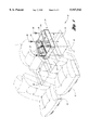
- FIG. 1 shows a partially exploded, schematically arranged perspective view of a vehicle seat riser assembly secured in a vehicle in accordance with the present invention
- FIG. 2 shows a perspective view of the seat riser assembly of FIG. 1 with the riser legs in the collapsed position
- FIG. 3 shows a perspective view of the seat riser assembly of FIG. 1 with the riser legs in the upright position
- FIG. 5 shows an exploded perspective view of a latch hook assembly for attaching the seat to the riser as shown in FIG. 4;
- FIG. 6 shows vertical cross-sectional view of a seat riser assembly secured in a vehicle in accordance with the present invention
- FIG. 7 shows a vertical cross-sectional view of a seat riser assembly secured in a vehicle with the riser leg in the upright position in accordance with the detail shown in FIG. 6;
- FIG. 8 shows a vertical cross-sectional view of a seat riser assembly secured in a vehicle in accordance with the present invention with the riser leg in the collapsed position.
- a vehicle passenger compartment 10 is shown to include front seats 12,14, and a plurality of recesses 16,18,20 formed in the vehicle floor 22. Each recess 16,18,20 is adapted to receive a collapsible riser assembly 24.
- the collapsible riser assembly 24 includes a one-piece pan or base 26 which is secured within the recess 16 by bolts 28.
- the floor recesses 16,18,20 are approximately 70 millimeters deep in order to enclose the collapsed riser assembly 24 when the riser legs 30,32 are collapsed within the pan 26.
- the one-piece base 26 is configured as a pan with side walls 34, 36, 38, 40.
- the riser legs 30,32 are pivotally connected to the base 26 by the pivot tubes 42,44 for facilitating pivotal movement between the collapsed position shown in FIG. 2 and the upright position shown in FIG. 3. With the riser legs 30,32 in the collapsed position shown in FIG. 2, vehicle storage capacity is increased in the passenger compartment 10.
- a seat belt latch 46 is pivotally mounted to the riser leg 30 at the pivot joint 48 for pivotal movement between the collapsed position shown in FIG. 2 and the extended position shown in FIG. 3.
- a latch 50 is also provided on the base 26 for selectively latching the riser legs 30,32 in the collapsed position.
- the riser legs 30,32 are spring-biased toward the upright position, and automatically move to the upright position as a result of the spring bias when the latch 50 is operated to release the riser legs 30,32 from the collapsed position.
- attachment features 54,56 are mounted on the riser legs 30,32 for attachment of the removable seat.
- location of the attachment features 54,56 is not subject to a stack-up of tolerances of numerous components, therefore the attachment features 54,56 may be repeatably, accurately located for receiving the removable seat.
- the removable seat 60 preferably comprises a number of aluminum tubes or other lightweight structure which form a back frame and lower seat frame, including tubes 62,64.
- the tubes are lightweight, which reduces weight of the assembly.
- Attachment hooks 66,68 are secured to the tubes 62,64 for engagement with the attachment features 54,56 on the risers 30,32.
- the rear hooks 68 are pivotally connected to the seat 60 by the pins 70,72.
- Torsional springs 74,76 pivotally bias the hooks 68 toward a latched position about the attachment features 56, and a handle 78 is provided for disengaging the rear hooks 68 from the attachment features 56 against the bias of the torsional springs 74,76.
- attachment feature 54 is engaged by hook 66, which extends through the slot 55, and attachment feature 56 is engaged by pivotable hook 68. Also, the seat 60 is easily removed by operating the handle 78 to disengage the hooks 68.
- Stop beads 82,84 formed in the bottom of the base 26, as shown in FIG. 7, are configured to limit the travel of the riser legs 30,32 to the upright position by abutting the bottom edge 86 of the riser legs 30,32.
- FIGS. 6, 7 and 8 illustrate the recess 16 formed in the vehicle floor, as well as the insulator 88 and carpet 90.
- a cross-car floor reinforcement 92 may also be provided for adding structural integrity to the vehicle floor.
- FIG. 6 also illustrates the mounting of the pivot tube 42 on a bushing 94, and further illustrates the torsional spring 96 which pivotally biases the riser legs 30 toward the upright position.
- a flange 98 is provided along the edge of the riser assembly for covering the edge of the carpet 90.
- the present invention achieves the stated objects of a collapsible riser and lightweight removable seat, wherein tolerance stack-up effect on attachment features is minimized. Also, by building the seat support angle into the riser legs 30,32, further structural weight is reduced from the removable seat 60.
Landscapes
- Engineering & Computer Science (AREA)
- Aviation & Aerospace Engineering (AREA)
- Transportation (AREA)
- Mechanical Engineering (AREA)
- Seats For Vehicles (AREA)
Abstract
Description
Claims (14)
Priority Applications (1)
| Application Number | Priority Date | Filing Date | Title |
|---|---|---|---|
| US08/948,346 US5947542A (en) | 1997-10-09 | 1997-10-09 | Vehicle seat assembly with collapsible riser |
Applications Claiming Priority (1)
| Application Number | Priority Date | Filing Date | Title |
|---|---|---|---|
| US08/948,346 US5947542A (en) | 1997-10-09 | 1997-10-09 | Vehicle seat assembly with collapsible riser |
Publications (1)
| Publication Number | Publication Date |
|---|---|
| US5947542A true US5947542A (en) | 1999-09-07 |
Family
ID=25487697
Family Applications (1)
| Application Number | Title | Priority Date | Filing Date |
|---|---|---|---|
| US08/948,346 Expired - Fee Related US5947542A (en) | 1997-10-09 | 1997-10-09 | Vehicle seat assembly with collapsible riser |
Country Status (1)
| Country | Link |
|---|---|
| US (1) | US5947542A (en) |
Cited By (4)
| Publication number | Priority date | Publication date | Assignee | Title |
|---|---|---|---|---|
| US20040227386A1 (en) * | 2003-05-15 | 2004-11-18 | Toshiyuki Tsujibayashi | Detachable seat for vehicle |
| US7300088B1 (en) * | 2006-12-22 | 2007-11-27 | Chrysler Llc | Collapsible vehicle storage container |
| DE102007054085A1 (en) * | 2007-11-13 | 2009-05-14 | Euromotive Gmbh & Co. Kg | Backrest for a motor vehicle seat and method for its manufacture |
| US20170088030A1 (en) * | 2015-09-28 | 2017-03-30 | John DeLeon | Collapsible Organizer for in-Vehicle Storage |
Citations (11)
| Publication number | Priority date | Publication date | Assignee | Title |
|---|---|---|---|---|
| US3151906A (en) * | 1962-12-19 | 1964-10-06 | Herbert B Roberts | Multiple purpose vehicle seat |
| US3746389A (en) * | 1970-02-17 | 1973-07-17 | Renault | Folding seats for automotive vehicles |
| US4341415A (en) * | 1978-12-23 | 1982-07-27 | Westfalia-Werke Franz Knobel & Sohne Kg | Vehicle having at least two rows of tandem seats |
| US4708387A (en) * | 1985-01-30 | 1987-11-24 | Ikeda Bussan Co., Ltd. | Take-down seat for automobile |
| US4946216A (en) * | 1989-09-28 | 1990-08-07 | Hoover Universal, Inc. | Vehicle with integrated seat risers |
| US5116097A (en) * | 1989-10-17 | 1992-05-26 | Gianni Bulgari S.P.A. | Motor car with three front seats side by side |
| US5482346A (en) * | 1993-10-26 | 1996-01-09 | Cesa-Compagnie Europeene De Sieges Pour Automobiles | Fold-away auxiliary seat unit for a vehicle |
| US5492386A (en) * | 1994-05-04 | 1996-02-20 | Ford Motor Company | Flexible seating arrangement for a mini van |
| US5527087A (en) * | 1993-10-28 | 1996-06-18 | Aisin Seiki Kabushiki Kaisha | Vehicle seat apparatus including a locking mechanism |
| US5611589A (en) * | 1994-02-03 | 1997-03-18 | Ikeda Bussan Co., Ltd. | Seat arrangement for motor vehicle |
| US5662367A (en) * | 1994-09-02 | 1997-09-02 | Mercedes-Benz Ag | Removable motor vehicles rear seat |
-
1997
- 1997-10-09 US US08/948,346 patent/US5947542A/en not_active Expired - Fee Related
Patent Citations (11)
| Publication number | Priority date | Publication date | Assignee | Title |
|---|---|---|---|---|
| US3151906A (en) * | 1962-12-19 | 1964-10-06 | Herbert B Roberts | Multiple purpose vehicle seat |
| US3746389A (en) * | 1970-02-17 | 1973-07-17 | Renault | Folding seats for automotive vehicles |
| US4341415A (en) * | 1978-12-23 | 1982-07-27 | Westfalia-Werke Franz Knobel & Sohne Kg | Vehicle having at least two rows of tandem seats |
| US4708387A (en) * | 1985-01-30 | 1987-11-24 | Ikeda Bussan Co., Ltd. | Take-down seat for automobile |
| US4946216A (en) * | 1989-09-28 | 1990-08-07 | Hoover Universal, Inc. | Vehicle with integrated seat risers |
| US5116097A (en) * | 1989-10-17 | 1992-05-26 | Gianni Bulgari S.P.A. | Motor car with three front seats side by side |
| US5482346A (en) * | 1993-10-26 | 1996-01-09 | Cesa-Compagnie Europeene De Sieges Pour Automobiles | Fold-away auxiliary seat unit for a vehicle |
| US5527087A (en) * | 1993-10-28 | 1996-06-18 | Aisin Seiki Kabushiki Kaisha | Vehicle seat apparatus including a locking mechanism |
| US5611589A (en) * | 1994-02-03 | 1997-03-18 | Ikeda Bussan Co., Ltd. | Seat arrangement for motor vehicle |
| US5492386A (en) * | 1994-05-04 | 1996-02-20 | Ford Motor Company | Flexible seating arrangement for a mini van |
| US5662367A (en) * | 1994-09-02 | 1997-09-02 | Mercedes-Benz Ag | Removable motor vehicles rear seat |
Cited By (7)
| Publication number | Priority date | Publication date | Assignee | Title |
|---|---|---|---|---|
| US20040227386A1 (en) * | 2003-05-15 | 2004-11-18 | Toshiyuki Tsujibayashi | Detachable seat for vehicle |
| US7137663B2 (en) * | 2003-05-15 | 2006-11-21 | Ts Tech Co., Ltd. | Detachable seat for vehicle |
| CN1550371B (en) * | 2003-05-15 | 2010-09-01 | 东京座椅技术股份公司 | Detachable seat for vehicle |
| US7300088B1 (en) * | 2006-12-22 | 2007-11-27 | Chrysler Llc | Collapsible vehicle storage container |
| DE102007054085A1 (en) * | 2007-11-13 | 2009-05-14 | Euromotive Gmbh & Co. Kg | Backrest for a motor vehicle seat and method for its manufacture |
| US20170088030A1 (en) * | 2015-09-28 | 2017-03-30 | John DeLeon | Collapsible Organizer for in-Vehicle Storage |
| US10214130B2 (en) * | 2015-09-28 | 2019-02-26 | John DeLeon | Collapsible organizer for in-vehicle storage |
Similar Documents
| Publication | Publication Date | Title |
|---|---|---|
| US10994645B2 (en) | Side-by-side utility vehicle | |
| US6398291B1 (en) | Collapsible vehicle mid-gate with seat components fixed thereon | |
| US6129404A (en) | Seat arrangement for a vehicle | |
| US4527828A (en) | Side mounted jump seat for an automotive vehicle | |
| US6883854B2 (en) | Stowable rear seat for vehicle passenger compartments | |
| US6089641A (en) | Passenger vehicle floor and seat arrangement | |
| US5707103A (en) | Storable and removable seat assembly | |
| US6073986A (en) | Easily handled movable vehicle seat assembly | |
| US5871255A (en) | Vehicle seat | |
| US5704685A (en) | Vehicle rear seat provided with child seat | |
| US5382083A (en) | Light weight vehicle seat frame | |
| US20050264048A1 (en) | Seat and cargo carrier apparatus | |
| US6224132B1 (en) | Easily handled movable vehicle seat assembly | |
| US4218091A (en) | Reclinable vehicle chair and conversion method | |
| US20100289290A1 (en) | Stowable seat and seat storage structure | |
| US10946775B2 (en) | Vehicle seat storage system | |
| US5947542A (en) | Vehicle seat assembly with collapsible riser | |
| US6158799A (en) | Seat positioning method and apparatus | |
| US2235751A (en) | Spare seat for an automotive cab | |
| JPS6337302Y2 (en) | ||
| JPH0239878Y2 (en) | ||
| JPH10129354A (en) | Seat for automobile with separator | |
| JP3492500B2 (en) | Seat back frame structure for automotive seat equipment | |
| JP2002370613A (en) | On-vehicle load coupling device to body floor of automobile | |
| JPH0121864Y2 (en) |
Legal Events
| Date | Code | Title | Description |
|---|---|---|---|
| AS | Assignment |
Owner name: LEAR CORPORATION, MICHIGAN Free format text: ASSIGNMENT OF ASSIGNORS INTEREST;ASSIGNORS:LUX, DONALD A.;MASSARA, ANDREW J.;BAN, MARCEL C.;AND OTHERS;REEL/FRAME:009087/0556;SIGNING DATES FROM 19980303 TO 19980320 |
|
| CC | Certificate of correction | ||
| FEPP | Fee payment procedure |
Free format text: PAYOR NUMBER ASSIGNED (ORIGINAL EVENT CODE: ASPN); ENTITY STATUS OF PATENT OWNER: LARGE ENTITY Free format text: PAYER NUMBER DE-ASSIGNED (ORIGINAL EVENT CODE: RMPN); ENTITY STATUS OF PATENT OWNER: LARGE ENTITY |
|
| FPAY | Fee payment |
Year of fee payment: 4 |
|
| AS | Assignment |
Owner name: JPMORGAN CHASE BANK, N.A., AS GENERAL ADMINISTRATI Free format text: SECURITY AGREEMENT;ASSIGNOR:LEAR CORPORATION;REEL/FRAME:017858/0719 Effective date: 20060425 |
|
| REMI | Maintenance fee reminder mailed | ||
| LAPS | Lapse for failure to pay maintenance fees | ||
| LAPS | Lapse for failure to pay maintenance fees |
Free format text: PATENT EXPIRED FOR FAILURE TO PAY MAINTENANCE FEES (ORIGINAL EVENT CODE: EXP.); ENTITY STATUS OF PATENT OWNER: LARGE ENTITY |
|
| STCH | Information on status: patent discontinuation |
Free format text: PATENT EXPIRED DUE TO NONPAYMENT OF MAINTENANCE FEES UNDER 37 CFR 1.362 |
|
| FP | Lapsed due to failure to pay maintenance fee |
Effective date: 20070907 |
|
| AS | Assignment |
Owner name: LEAR CORPORATION, MICHIGAN Free format text: RELEASE BY SECURED PARTY;ASSIGNOR:JPMORGAN CHASE BANK, N.A.;REEL/FRAME:032722/0553 Effective date: 20100830 |
|
| AS | Assignment |
Owner name: LEAR CORPORATION, MICHIGAN Free format text: RELEASE BY SECURED PARTY;ASSIGNOR:JPMORGAN CHASE BANK, N.A., AS AGENT;REEL/FRAME:037731/0918 Effective date: 20160104 |