EP1097314B1 - Low contact force spring - Google Patents
Low contact force spring Download PDFInfo
- Publication number
- EP1097314B1 EP1097314B1 EP99937400A EP99937400A EP1097314B1 EP 1097314 B1 EP1097314 B1 EP 1097314B1 EP 99937400 A EP99937400 A EP 99937400A EP 99937400 A EP99937400 A EP 99937400A EP 1097314 B1 EP1097314 B1 EP 1097314B1
- Authority
- EP
- European Patent Office
- Prior art keywords
- piston
- cushion assembly
- elastomeric material
- assembly
- condition
- Prior art date
- Legal status (The legal status is an assumption and is not a legal conclusion. Google has not performed a legal analysis and makes no representation as to the accuracy of the status listed.)
- Expired - Lifetime
Links
- 239000012530 fluid Substances 0.000 claims abstract description 76
- 239000013536 elastomeric material Substances 0.000 claims description 174
- 230000033001 locomotion Effects 0.000 claims description 21
- 239000000463 material Substances 0.000 claims description 14
- ALQLPWJFHRMHIU-UHFFFAOYSA-N 1,4-diisocyanatobenzene Chemical compound O=C=NC1=CC=C(N=C=O)C=C1 ALQLPWJFHRMHIU-UHFFFAOYSA-N 0.000 claims description 5
- JOYRKODLDBILNP-UHFFFAOYSA-N Ethyl urethane Chemical compound CCOC(N)=O JOYRKODLDBILNP-UHFFFAOYSA-N 0.000 claims description 4
- 239000000203 mixture Substances 0.000 claims description 4
- 229920002635 polyurethane Polymers 0.000 claims description 4
- 239000004814 polyurethane Substances 0.000 claims description 4
- 238000009472 formulation Methods 0.000 claims 1
- 230000000717 retained effect Effects 0.000 abstract 1
- 239000007789 gas Substances 0.000 description 26
- 230000000712 assembly Effects 0.000 description 23
- 238000000429 assembly Methods 0.000 description 23
- 230000035939 shock Effects 0.000 description 18
- 238000010276 construction Methods 0.000 description 16
- 230000006835 compression Effects 0.000 description 14
- 238000007906 compression Methods 0.000 description 14
- 238000007667 floating Methods 0.000 description 11
- 238000000418 atomic force spectrum Methods 0.000 description 10
- IJGRMHOSHXDMSA-UHFFFAOYSA-N Atomic nitrogen Chemical compound N#N IJGRMHOSHXDMSA-UHFFFAOYSA-N 0.000 description 9
- 239000002184 metal Substances 0.000 description 7
- 229910000831 Steel Inorganic materials 0.000 description 6
- 239000010959 steel Substances 0.000 description 6
- 230000003247 decreasing effect Effects 0.000 description 5
- 229910001873 dinitrogen Inorganic materials 0.000 description 5
- 230000036961 partial effect Effects 0.000 description 5
- 238000003825 pressing Methods 0.000 description 5
- 230000002829 reductive effect Effects 0.000 description 5
- 230000001050 lubricating effect Effects 0.000 description 4
- 229910000760 Hardened steel Inorganic materials 0.000 description 3
- 230000004323 axial length Effects 0.000 description 3
- 230000009977 dual effect Effects 0.000 description 3
- 238000000034 method Methods 0.000 description 3
- 230000036316 preload Effects 0.000 description 3
- 229910000906 Bronze Inorganic materials 0.000 description 2
- 239000004215 Carbon black (E152) Substances 0.000 description 2
- 230000008901 benefit Effects 0.000 description 2
- 239000010974 bronze Substances 0.000 description 2
- KUNSUQLRTQLHQQ-UHFFFAOYSA-N copper tin Chemical compound [Cu].[Sn] KUNSUQLRTQLHQQ-UHFFFAOYSA-N 0.000 description 2
- 238000013461 design Methods 0.000 description 2
- 229920001971 elastomer Polymers 0.000 description 2
- 229930195733 hydrocarbon Natural products 0.000 description 2
- 150000002430 hydrocarbons Chemical class 0.000 description 2
- 230000006872 improvement Effects 0.000 description 2
- 230000000977 initiatory effect Effects 0.000 description 2
- 150000002825 nitriles Chemical class 0.000 description 2
- 229910052757 nitrogen Inorganic materials 0.000 description 2
- 230000008569 process Effects 0.000 description 2
- 239000002994 raw material Substances 0.000 description 2
- 238000007789 sealing Methods 0.000 description 2
- 239000012815 thermoplastic material Substances 0.000 description 2
- VYZAMTAEIAYCRO-UHFFFAOYSA-N Chromium Chemical compound [Cr] VYZAMTAEIAYCRO-UHFFFAOYSA-N 0.000 description 1
- 229920006311 Urethane elastomer Polymers 0.000 description 1
- 230000009471 action Effects 0.000 description 1
- 238000013459 approach Methods 0.000 description 1
- 230000000295 complement effect Effects 0.000 description 1
- 230000008602 contraction Effects 0.000 description 1
- 238000013016 damping Methods 0.000 description 1
- 230000007423 decrease Effects 0.000 description 1
- 230000001419 dependent effect Effects 0.000 description 1
- 238000011161 development Methods 0.000 description 1
- 230000018109 developmental process Effects 0.000 description 1
- 230000003467 diminishing effect Effects 0.000 description 1
- 239000000428 dust Substances 0.000 description 1
- 230000008846 dynamic interplay Effects 0.000 description 1
- 230000000694 effects Effects 0.000 description 1
- 230000000670 limiting effect Effects 0.000 description 1
- 239000007788 liquid Substances 0.000 description 1
- 239000000314 lubricant Substances 0.000 description 1
- 238000005461 lubrication Methods 0.000 description 1
- 238000012423 maintenance Methods 0.000 description 1
- 230000014759 maintenance of location Effects 0.000 description 1
- 238000004519 manufacturing process Methods 0.000 description 1
- 230000007246 mechanism Effects 0.000 description 1
- 238000007747 plating Methods 0.000 description 1
- 238000005381 potential energy Methods 0.000 description 1
- 238000005507 spraying Methods 0.000 description 1
- 230000003068 static effect Effects 0.000 description 1
- 230000001052 transient effect Effects 0.000 description 1
- 238000003466 welding Methods 0.000 description 1
Images





Classifications
-
- F—MECHANICAL ENGINEERING; LIGHTING; HEATING; WEAPONS; BLASTING
- F16—ENGINEERING ELEMENTS AND UNITS; GENERAL MEASURES FOR PRODUCING AND MAINTAINING EFFECTIVE FUNCTIONING OF MACHINES OR INSTALLATIONS; THERMAL INSULATION IN GENERAL
- F16F—SPRINGS; SHOCK-ABSORBERS; MEANS FOR DAMPING VIBRATION
- F16F13/00—Units comprising springs of the non-fluid type as well as vibration-dampers, shock-absorbers, or fluid springs
- F16F13/002—Units comprising springs of the non-fluid type as well as vibration-dampers, shock-absorbers, or fluid springs comprising at least one fluid spring
-
- B—PERFORMING OPERATIONS; TRANSPORTING
- B21—MECHANICAL METAL-WORKING WITHOUT ESSENTIALLY REMOVING MATERIAL; PUNCHING METAL
- B21D—WORKING OR PROCESSING OF SHEET METAL OR METAL TUBES, RODS OR PROFILES WITHOUT ESSENTIALLY REMOVING MATERIAL; PUNCHING METAL
- B21D24/00—Special deep-drawing arrangements in, or in connection with, presses
- B21D24/02—Die-cushions
-
- F—MECHANICAL ENGINEERING; LIGHTING; HEATING; WEAPONS; BLASTING
- F16—ENGINEERING ELEMENTS AND UNITS; GENERAL MEASURES FOR PRODUCING AND MAINTAINING EFFECTIVE FUNCTIONING OF MACHINES OR INSTALLATIONS; THERMAL INSULATION IN GENERAL
- F16F—SPRINGS; SHOCK-ABSORBERS; MEANS FOR DAMPING VIBRATION
- F16F9/00—Springs, vibration-dampers, shock-absorbers, or similarly-constructed movement-dampers using a fluid or the equivalent as damping medium
- F16F9/003—Dampers characterised by having pressure absorbing means other than gas, e.g. sponge rubber
-
- F—MECHANICAL ENGINEERING; LIGHTING; HEATING; WEAPONS; BLASTING
- F16—ENGINEERING ELEMENTS AND UNITS; GENERAL MEASURES FOR PRODUCING AND MAINTAINING EFFECTIVE FUNCTIONING OF MACHINES OR INSTALLATIONS; THERMAL INSULATION IN GENERAL
- F16F—SPRINGS; SHOCK-ABSORBERS; MEANS FOR DAMPING VIBRATION
- F16F9/00—Springs, vibration-dampers, shock-absorbers, or similarly-constructed movement-dampers using a fluid or the equivalent as damping medium
- F16F9/02—Springs, vibration-dampers, shock-absorbers, or similarly-constructed movement-dampers using a fluid or the equivalent as damping medium using gas only or vacuum
- F16F9/0209—Telescopic
- F16F9/0218—Mono-tubular units
-
- F—MECHANICAL ENGINEERING; LIGHTING; HEATING; WEAPONS; BLASTING
- F16—ENGINEERING ELEMENTS AND UNITS; GENERAL MEASURES FOR PRODUCING AND MAINTAINING EFFECTIVE FUNCTIONING OF MACHINES OR INSTALLATIONS; THERMAL INSULATION IN GENERAL
- F16F—SPRINGS; SHOCK-ABSORBERS; MEANS FOR DAMPING VIBRATION
- F16F9/00—Springs, vibration-dampers, shock-absorbers, or similarly-constructed movement-dampers using a fluid or the equivalent as damping medium
- F16F9/32—Details
- F16F9/48—Arrangements for providing different damping effects at different parts of the stroke
Definitions
- the subject invention relates to a press assembly and, more particularly, to a press assembly having a cushion assembly which provides a yieldable force during operation of the press assembly from an open condition to a closed condition.
- a die can comprise a complex and expensive device that punches holes, cuts, bends, forms, etc. raw material (e.g., sheet metal and the like) that is placed within the die.
- raw material e.g., sheet metal and the like
- automobile fenders, side panels, etc. are typically formed from sheet steel that is placed within a die.
- a die is typically operated by a mechanical pressing mechanism that can generate large amounts of force for pressing the die components together when the raw material is placed therein.
- a typical mechanical press can generate tons of pressing force depending upon its design.
- Most mechanical presses employ a large rotating flywheel arrangement and use a crankshaft or eccentric shaft to convert the rotary motion of the flywheel to a straight line pressing motion which is applied to a slide that contacts a portion of the die.
- the geometry of this combination of parts results in a changing mechanical advantage between the drive and the slide.
- the mechanical advantage of the crank arm and connection assembly will vary from one, at a point near midstroke, to infinity at the bottom of the stroke.
- the cushion assembly 10 comprises a body 12 that slidably supports a piston 16 therein.
- the piston 16 is attached to a piston rod 18 that is oriented in the mechanical press to engage the bottom of the die or a movable table (known as a pin plate) that supports the die.
- the body 12 is hollow and is capped on one end by a cap 14.
- the cap 14 and the bottom of the piston 16 cooperate to define a gas chamber 20.
- the gas chamber 20 is charged with a compressible gas, such as nitrogen, through a conventional pressure valve 22 located in the cap 14.
- the piston rod 18 is slidably supported within the body 12 by a rigid rod support member 24 that is typically fabricated out of metal such as bronze.
- the upper end 13 of the body 12 is sealed with a retainer cap 26 that is affixed in position with a conventional retaining ring 28.
- the gas pressure within the chamber 20 serves to push the piston rod 18 out of the body 12 until the piston 16 contacts the rigid retainer 24.
- Such construction results in the preloading of the piston rod 18 such that the development of a contact force (i.e., the force required to initiate movement of the spring from the fully extended position) on the end of the piston rod 18 is required to compress the gas spring 10.
- Figure 2 is a press tonnage curve of a typical mechanical press wherein known cushion assemblies of the type described above are employed.
- the vertical axis represents the amount of force (tonnage) generated by the press and the horizontal axis represents the distance that the press slide is away from its bottom limit of travel.
- the press load capacity increases along an arcuate slope to a certain point as the distance between the press slide and its bottom position increases.
- the tonnage signature is the actual application of forces by the press during operation and takes into account a variety of process variables such as speed, overloading, etc.
- the preload of the cushion assemblies can result in the undesirable shock overload depicted in Figure 2 wherein the actual load exceeds the press load capacity. Such shock loading can result in die and press wear and failure, excessive noise, and undesirable pad bounce.
- Swedish Patent No. 9401119-4 discloses a cushion assembly that employs a floating piston and a dual gas chamber arrangement. This reference also teaches that a damping body may also be employed to "further damp any residual noise.” Such a cushion assembly requires additional sealing elements to be employed and produces undesirable dynamic effects due to inertia of the floating piston, and static friction of the seals.
- Figure 3 is a graphical comparison of the theoretical force curves of a conventional cushion assembly or gas spring of the type depicted in Figure 1 and the above-mentioned spring that employs a floating piston.
- the floating piston represents a modest improvement over the standard gas spring in that its initial curve (upon contact) is slightly sloped when compared to the essentially vertical curve of the conventional gas spring.
- FIG. 4 is a graphical comparison of the force curves of a conventional gas spring of the type depicted in Figure 1 and a conventional gas spring that employs a stepped piston. As can be seen in that Figure, however, the undesirable instantaneous step function in the spring load is not eliminated when utilizing a spring with such a piston arrangement.
- US 5007276 discloses a press assembly operable from an open condition to a closed condition to deform a workpiece and operable from the closed condition to the open condition to facilitate removal of the workpiece from said press assembly, said press assembly comprising a first member for engaging a first side of the workpiece, a second member for engaging a second side of the workpiece, drive means for moving said first member toward said second member during operation of said press assembly from the open condition to the closed condition and for moving said first member away from said second member during operation of said press assembly from the closed condition to the open condition, and a cushion assembly operable from an extended condition toward a retracted condition to provide a yieldable force during at least a portion of the operation of the press assembly from the open condition toward the closed condition, said cushion assembly including a cylinder and a piston, said piston having a head end portion which is disposed in said cylinder and a rod end portion which extends from said head end portion through one end of said cylinder, said head end portion of said piston cooperates with said cylinder to at least partially define
- the present invention provides a press assembly as defined in the last preceding paragraph characterized by the cushion assembly including a body of elastomeric material disposed in said cylinder, said body of elastomeric material being effective to urge said head end portion of said piston away from said one end of said cylinder against the influence of fluid pressure in said chamber when said cushion assembly is in the extended condition, said body of elastomeric material being effective to provide force which assists force transmitted from said drive means to said cushion assembly during an initial portion of the operation of said cushion assembly from the extended condition toward the retracted condition.
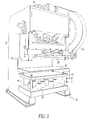
- press 30 has a frame 32 and a flywheel 34 operably attached thereto.
- a crankshaft 36 is attached to the flywheel and a slide plate or upper member 38 is attached to the bottom of the crankshaft.
- a die or lower member 40 may be supported on a pin plate 42 that is slidably supported on a plurality of springs 50 and a series of guide posts 44.
- the slide plate 38 travels up and down in the directions represented by arrows (B, C).
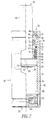
- Figure 6 depicts one press cushion assembly for use in an embodiment of the present invention.
- the press cushion assembly or spring 50 includes a body member 52 that is preferably fabricated from steel such that it defines a piston receiving passage 54 therein.
- An end cap 56 is preferably attached to the bottom of the body member 52, preferably by welding or other suitable means, to create a fluid-tight seal between the end cap 56 and the body 52.
- a piston assembly 58 preferably fabricated from hardened steel, is sized to be slidably received within the passageway 54.
- an annular piston bearing 62 preferably fabricated from bronze, is pressed into an annular cavity 60 within the piston assembly 58.
- Piston assembly 58 includes a head end portion and a rod end portion.
- the rod end portion includes a piston rod 64 that is preferably fabricated from hardened steel covered with chrome plating.
- Piston rod 64 has a first end 66 that protrudes from the passageway 54 and is adapted to engage a portion of a machine such as a pin plate 42 of a mechanical press 30.
- the other end 68 of the piston rod 64 is adapted to be affixed to and forms part of the head end portion of the piston assembly 58.
- a shoulder 65 is preferably machined into the end 68 of the piston rod 64 at the head end portion of the piston assembly, as shown in Figure 6.
- Piston assembly 58 in a preferred form, consists of two piston halves 59 that each have a complementary step 61 machined therein that is constructed to interface with the shoulder 65 in the piston rod 64 as shown.
- an annular piston bearing 62 preferably fabricated from a polymeric material, is assembled into an annular cavity 60 within the piston assembly 58. Referring to Figure 7, when assembled, a passageway 63 is provided between the halves 59 to permit pressurized fluid to pass therebetween.
- the halves 59 of piston 58 are arranged on the shoulder portion 65 of the piston rod 64 and the piston bearing 62 is installed around the two piston halves 59. The piston assembly is then slid into the passageway 54.
- the skilled artisan will readily appreciate, however, that other methods of affixing the piston assembly 58 to the piston rod 64 may also be employed.
- Piston rod 64 is slidably supported within the passageway 54 by a piston rod support member 70 and a retaining cap 90.
- the piston rod support member 70 is preferably fabricated from a rigid material such as steel and has a flanged upper portion 72 and a cylindrical body portion 74.
- a through passage 76 extends through the flanged portion 72 and the body portion 74 to slidably receive the piston rod 64 therethrough.
- a cavity 73 is preferably provided in the flanged portion 72 for receiving a commercially available "U-cup" 75 therein.
- an O-ring 79 is preferably seated in an annular passage 77 machined in the perimeter of the flanged portion 72 of the piston rod support member 70.
- a cavity is preferably formed between the body 52 and the body portion 74 of the piston rod support member 70 for receiving a biasing unit which is an annular body 84 of elastomeric material.
- bumper member 84 comprises an elastomeric material such as urethane.
- urethane urethane
- other materials such as nitrile or fluorinated hydrocarbon could also be successfully employed. The purpose of the bumper member 84 will be discussed in further detail below.
- the spring assembly 50 preferably further includes a retainer cap 90 that is removably affixed to the body 52 by a commercially available retainer ring 92.
- a rubber dust seal member 93 is inserted in the groove between the body 52 and the retainer cap 90 as shown in Figure 6.
- Retainer cap 90 has a passage 94 therethrough that is adapted to slidably receive the piston rod 64.
- an annular cavity 96 is coaxially aligned with passage 94 to receive a commercially available scraper ring 98 therein.
- Scraper ring 98 is preferably fabricated from polyurethane.
- the lower surface of the piston assembly 58 cooperates with the end cap 56 attached to the body 52 to define a fluid chamber 100 within the passageway 54. See Figure 6.
- the fluid chamber 100 is preferably charged with a gaseous medium through a commercially available charging valve 102 installed in the end cap and communicating with a passageway 104 that adjoins the fluid chamber 100.
- the construction and operation of the charging valve 102 is well known in the art and, as such, will not be discussed in detail herein.
- the fluid chamber 100 is charged with a pressurized fluid.
- a pressurized fluid can comprise a liquid medium or a gaseous medium.
- a fluid medium such as nitrogen gas at a preferred pressure of 2175 psi (14996 x 10 3 Pa) is employed.
- other mediums such as oil at pressures dictated by the particular application can also be successfully used.
- a rod seal device such as this, the piston halves 59 do not compress the fluid, due to the passageway 63 which allows the fluid to flow across the piston 58.
- the piston halves 59 act only to guide and retain the piston rod 64.
- the fluid is compressed by the rod moving into the fluid chamber and taking up some of the volume used by the fluid.
- the force in a rod seal device is generated by the fluid pressure within the chamber 100 pushing on the rod end 68.
- Figure 8 is a graphical comparison of the force curves of a conventional spring member of the type depicted in Figure 1 and the spring of the present invention shown in Figure 7.
- Line “D” in that Figure represents the force curve for a conventional spring 10 of the type depicted in Figure 1.
- Line “E” represents the force curve for a spring 50 of the present invention as shown in Figure 7.
- the force curve for spring 50 has a lower contact force (i.e., the force needed to initiate spring movement at 0%) than the force curve of spring 10.
- the bumper member 84 of the present invention serves to balance the force exerted on the piston rod 64 by the gas pressure within the chamber 100.
- the net force exerted by the piston rod 64 is reduced by the balancing force from the bumper member 84 as shown in Figure 9.
- the characteristics of the resulting force curve of the spring 50 of the present invention (line E in Figure 8) are controlled by the relative stiffness of the bumper member 84 as well as the compression distance "F” as shown in Figure 9.
- the resultant force curve "E” in Figure 8 is the force curve for a conventional spring, such as shown by curve “D", minus the force required to compress the bumper.
- the bumper is preferably completely uncompressed and the curve “E” follows curve “D” (the two curves are shown slightly separated in Figure 8 for clarity).
- the rigid retainer member 70 provides for a positive repeatable extended height of the piston rod 64 as well as acting as a compression limiter for the bumper member 84. to the construction of spring 50, except for the differences discussed below.
- the retainer member 170 is cylindrical in shape and is fabricated from a rigid material such as steel. Retainer member 170 has a hole 172 extending therethrough for receiving the piston rod 64.
- a cavity 174 is provided in the upper end of the retainer member 170 for receiving a commercially available U-cup member 75 therein.
- a second cavity 176 is provided in the bottom portion of the retainer member 170 and is adapted to receive a collection of disc springs 178 (commonly known as Belleville washers) which collectively act as a bumper member 184.
- Belleville washers commonly known as Belleville washers
- Figure 11 depicts another embodiment of the present invention.
- the spring 250 depicted in Figure 11 is identical in construction as to the spring 150, except that the Belleville washers have been replaced with a commercially available coil spring 278. Again the skilled artisan will appreciate that the contact force characteristics of the spring 250 can be adjusted by altering the coil spring strength.
- FIG. 12 Another embodiment of the present invention is depicted in Figure 12.
- the spring 350 illustrated therein is substantially identical to spring 50 except for the differences discussed below.
- piston rod 364 is integrally formed with the piston 358 from hardened steel.
- a cavity 360 is formed in the outer perimeter of the piston portion 358 for receiving a pair of commercially available U-cups 363 that serve to form a substantially fluid-tight sliding seal between the piston portion 358 and the body member 52.
- the cavity 82 in the rigid retainer member 70 forms a second fluid chamber 382 that is charged with a second amount of pressurized fluid, preferably nitrogen gas, through a secondary fill port 383 that is provided in the piston rod 364.
- a charge valve 102 is also provided in the end of the piston rod 364 to facilitate charging of chamber 382 and retention of the pressurized fluid therein.
- the gas in the second fluid chamber 382 serves as a bumper member for the piston 358.
- Figure 13 depicts another embodiment of the present invention.
- the spring 450 depicted in Figure 13 is substantially similar to spring 50 except for the following differences.
- the piston rod retainer 470 is fabricated from rigid material such as steel and has a hole 472 therethrough for slidably receiving the piston rod 64.
- An annular cavity 474 is preferably provided in the outer circumference of the retainer 470 for receiving an O-ring 476 therein.
- O-ring 476 serves to establish a fluid-tight seal between the retainer member 470 and the body 52.
- Retainer 470 additionally has a cavity 478 therein that is adapted to receive a commercially available U-cup 479 therein.
- a second cavity 480 is provided in the retainer 470 for receiving a second O-ring 482 therein to establish a fluid-tight seal between the piston rod
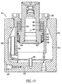
- FIG. 10 depicts a spring assembly 510 that is constructed with a self-lubricating piston cylinder unit 520.
- Spring 510 includes a body 512 that defines a piston-receiving cavity 514 therein that is sized to receive a piston cylinder unit 520.
- Piston cylinder unit 520 is attached to the body 512 preferably by means of a threaded connection.
- the piston cylinder unit 520 includes a piston 522 that is adapted to slide within the piston cylinder wall member 524. Piston 522 is fitted with a U-cup seal member 528 to establish a fluid-tight seal between the cylinder wall 524 and the piston 522.
- a commercially available charge valve 530 is provided in the bottom of the body 512.
- the charge valve 530 communicates with a passage 532 that communicates with an upwardly extending standpipe 534.
- Such arrangement permits a compressible gas such as nitrogen to be admitted into the piston-receiving cavity 514.
- a lubricating medium 542 such as oil can be pumped into the piston-receiving cavity 514 through a lubrication passage 540 in the bottom of the body member 512.
- Body member 512 is also preferably formed with an oil expansion reservoir 550. When the piston 522 is compressed towards the bottom of the body 512, the gas and lubricating medium 542 is forced into the oil expansion reservoir 550.
- a cavity 552 is formed between the piston 522 and the cylinder wall 524 as shown in Figure 10.
- a steel sleeve 554 is provided around the piston 522 and an elastomeric bumper member 560 is provided between a pair of washers 562 as shown.
- the bumper member 560 is preferably comprised of urethane elastomer. However, other materials such as nitrile or fluorinated hydrocarbon could be successfully employed.
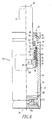
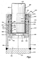
- a press cushion assembly 620 constructed in accordance with another embodiment of the present invention is illustrated in Fig. 11.
- the press cushion assembly 620 is used in a press assembly, which may have a construction similar to the construction of the press assembly 30 illustrated in Fig. 5.
- the cushion assembly 620 could be associated with an upper member in the press assembly, such as the slide plate 38.
- the press cushion assembly 620 could also be associated with movable draw rings in a press, in a manner similar to that disclosed in U.S. Patent No. 5,003,807.
- any one of the embodiments of the cushion assemblies disclosed herein could be used in many different types of press assemblies which are operable from an open condition to a closed condition to deform a workpiece.
- the cushion assemblies disclosed herein may be used in association with many different components of a press assembly.
- the cushion assemblies disclosed herein could be used in association with double action forming dies, ram levelers, bump dies, cam pads and returns, and/or multiple die sets.
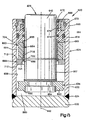
- the press cushion assembly 620 is operable from an extended condition illustrated in Fig. 11 through a partially retracted condition, illustrated in Fig. 12, to a fully retracted condition, illustrated in Fig. 13. During operation of the press cushion assembly 620 from the extended condition to the retracted condition, the press cushion assembly provides a yieldable force opposing movement of one member in a press assembly, for example the slide plate 38 of Fig. 5, relative to another member in the press assembly, for example, the die 40.
- the press cushion assembly 620 could be used with other components of a press assembly.
- the cushion assembly 620 includes a cylinder 624 (Fig. 11) and a piston 626.
- the cylinder 624 includes a cylindrical side wall 630 and a circular end wall 632.
- the side wall 630 and end wall 632 are interconnected at an annular weld 634.
- a plurality of cushion assemblies 620 could be associated with a manifold plate, in a manner similar to the disclosures in U.S. Patent Nos. 4,583,722; 4,765,227; and 4,257,254.
- the piston 626 includes a head end portion 638 and a rod end portion 640.
- the rod end portion 640 has a cylindrical configuration and is coaxial with a central axis 642 of the press cushion assembly 20.
- the rod end portion 640 of the piston 626 extends through an upper (as viewed in Fig. 11) end portion 646 of the cylinder 624.
- the cylinder 624 may be connected with a lower portion of the press assembly 30 (Fig. 5) or connected with an upper portion of the press assembly.
- the cylinder 624 could be connected with a stationary base of the press assembly. If the cylinder 624 is connected with the stationary base of the press assembly 30, the cushion assembly 620 would be disposed in the orientation illustrated in Fig. 11 with the piston 626 extending upward from the cylinder 624.
- the cylinder 624 could be associated with the movable slide plate 38 of the press assembly. If this is done, the orientation of the press cushion assembly 620 would be offset by 180° from the orientation illustrated in Fig. 11 so that the piston 626 would extend downward from the cylinder 624.
- the head end portion 638 of the piston 626 includes a pair of flange members 650 and 652 which extend into an annular groove 654. Each of the flange members 650 and 652 has a semicircular configuration. The flange members 650 and 652 are disposed in a circular array having its center on the axis 642. It should be understood that the flange members 650 and 652 do not sealingly engage a cylindrical inner side surface 656 of the cylinder 624. One or more openings may be provided between the flange members 650 and 652.
- the cylinder 624 cooperates with the piston 626 to define a variable volume chamber 660.
- the chamber 660 holds a fluid, such as nitrogen gas, under pressure.
- fluids other than nitrogen gas could be utilized.
- the cylinder 624 includes a guide assembly 664 which guides movement of the piston 626 relative to the inner side surface 656 of the side wall 630 of the cylinder 624.
- the guide assembly 664 has a central axis which is coincident with the axis 642.
- the guide assembly 664 includes an annular metal guide ring 666 which engages a cylindrical outer side surface 667 of the rod end portion 640 of the piston 626.
- the guide ring 666 guides movement of the rod end portion 640 of the piston 626 relative to the cylinder 624.
- An annular metal end cap 668 abuts the guide ring 666 and holds the guide ring in place in the cylinder 624 during reciprocation of the piston 626.
- An annular retainer ring 670 transmits force between the end cap 668 and the side wall 630 of the cylinder 624 to hold the end cap in place.
- Suitable annular seals 672, 674, 676, and 678 cooperate with the end cap 668 and guide ring 666 to prevent leakage of fluid from the cylinder 624.
- the flange members 650 and 652 on the head end portion 638 of the piston 626 are pressed firmly against a stop member 684 by fluid pressure in the chamber 660. Force is transmitted from the stop member through the guide ring 666 and end cap 668 to the cylindrical side wall 630 of the cylinder 624 through the annular retainer ring 670.
- the stop member 684 is formed by a rigid metal sleeve having a tubular cylindrical configuration. A central axis of the tubular stop member 684 is coincident with the axis 642.
- An annular end surface 686 on the stop member 684 (Fig. 11) abuts an annular surface area on radially inner portions of the flange members 650 and 652.
- the end surface 686 on the stop member 684 and the flange members 650 and 652 cooperate to limit upward (as viewed in Fig. 11) movement of the piston 626 under the influence of fluid pressure in the chamber 660.
- An upper end portion 688 of the cylindrical stop member 684 is fixedly connected with the guide ring 666.
- a body 692 of elastomeric material is disposed in an annular chamber 694.
- the annular chamber 694 extends around and is coaxial with the rod end portion 640 of the piston 626.
- the chamber 694 is formed between a rigid metal annular force transmitting member 698 and the annular guide ring 666.
- the annular force transmitting member 698 is coaxial with and is pressed against the annular body 692 of elastomeric material by the flange members 650 and 652 on the head end portion 638 of the piston.
- the body 692 of elastomeric material has a tubular cylindrical overall configuration and an annular cross-sectional configuration, it is contemplated that the body of elastomeric material could have a different configuration if desired.
- the chamber 694 and force transmitting member 698 could have configurations which are different than the illustrated annular configuration.
- a plurality of force transmitting members could be provide to transmit force from the body 692 of elastomeric material to the head end portion 638 of the piston.
- a plurality of rod-shaped force transmitting members could be utilized to transmit force from a plurality of separate bodies of elastomeric material or from a single body of elastomeric material.
- axially extending inner and/or outer side surfaces of the body of elastomeric material could have configurations other than the illustrated configurations.
- the inner and outer side surfaces could be axially curved throughout the length of the side surfaces or adjacent axially opposite ends of the body 292 of elastomeric material.
- the inner side surface of the body 292 of elastomeric material could have arcuate surface areas which flare radially outward adjacent to axially opposite ends of the body of elastomeric material.
- the outer side surface of the body 292 of elastomeric material could have arcuate surface areas which taper radially inward adjacent to axially opposite ends of the body of elastomeric material.
- the tubular cylindrical body 692 of elastomeric material When the cushion assembly 620 is in the extended condition illustrated in Fig. 11, the tubular cylindrical body 692 of elastomeric material is axially compressed from its initial or free length by force applied against one end of the annular body of elastomeric material by the force transmitting member 698.
- the cylindrical stop member 684 extends around the rod end portion 640 of the piston 626 and is coaxial with the body 692 of elastomeric material and the flange members 650 and 652. The stop member 684 limits the extent of axial compression of the body 692 of elastomeric material.
- the body 692 of elastomeric material has a substantially constant volume. Therefore, when the body 692 of elastomeric material is axially compressed from its initial or free configuration, as illustrated in Fig. 11, the body of elastomeric material expands radially.
- the body 692 of elastomeric material is sized so that radially outward expansion of the body of elastomeric material does not result in engagement of a cylindrical outer side surface 704 on the body of elastomeric material with the cylindrical inner side surface 656 on the side wall 630. Therefore, radial force components are not transmitted between the body 692 of elastomeric material and the side wall 630 of the cylinder 624 when the cushion assembly 620 is in the extended condition illustrated in Fig. 11.
- the associated press assembly When the cushion assembly 620 is in the extended condition of Fig. 11, the associated press assembly is in the open condition, similar to the condition illustrated in Fig. 5 for the press assembly 30. At this time, the fluid pressure in the chamber 660 is effective to press the flange members 650 and 652 on the head end portion 638 of the piston 626 firmly against the annular end surface 686 on the stop member 684.
- the stop member 684 limits the extent of upward (as viewed in Fig. 11) movement of the head end portion 638 of the piston 626 under the influence of fluid pressure in the chamber 660.
- the flange members 650 and 652 on the head end portion 638 of the piston 626 are firmly pressed against an annular lower (as viewed in Fig. 16) side surface 710 of the force transmitting member 698.
- the annular lower side surface 710 on the force transmitting member 798 engages the flange members 650 and 652 at a location radially outward from the location where the end surface 686 on the stop member 684 engages the flange members. Therefore, when the cushion assembly 620 is in the extended condition of Fig. 11, the fluid pressure in the chamber 660 is effective to press the flange members 650 and 652 on the head end portion 638 of the piston 626 against both the stop member 684 and force transmitting member 698. However, it is the stop member 684 which limits the extent of upward movement of the piston 626.
- the forces applied against axially opposite ends of the body 692 of elastomeric material are effective to compress the body of elastomeric material in an axial direction, that is, in a direction parallel to the central axis 642 (Fig. 11) of the cushion assembly 620.
- the flange members 650 and 652 on the head end portion 638 of the piston 626 are also pressed firmly against the stop member 684 which limits the extent of axially upward (as viewed in Figs. 11 and 14) movement of the piston 626. Of course, this limits the extent of axial compression of the body 692 of elastomeric material.
- the body of elastomeric material expands in a radially outward direction.
- the radial expansion of the body 692 of elastomeric material results in the total volume of the body of elastomeric material remaining constant as the body of elastomeric material is axially compressed.
- the cylindrical stop member 684 engages a cylindrical inner side surface 718 on the body 692 of elastomeric material to block radially inward expansion of the body of elastomeric material. Therefore, the body 692 of elastomeric material expands only in a radially outward direction as the body of elastomeric material is axially compressed.
- the inner side surface 718 could flare radially outward so as to provide some space between the cylindrical stop member 684 and inner side surface 718 when the cushion assembly is in the fully retracted condition of Fig. 13.
- the cushion assembly 620 when the cushion assembly 620 is in the extended condition of Figs. 13 and 14, the cylinder outer side surface 704 of the body 692 of elastomeric material is spaced a relative small radial distance from the inner side surface 656 of the side wall 630. Therefore, the body 692 of elastomeric material is not effective to apply radially outward forces against the side wall 630 of the cylinder 624.
- the body 692 of elastomeric material is effective to provide force which is applied against the head end portion 638 of the piston 626 by the force transmitting member 698.
- the force transmitted from the body 692 of elastomeric material to the piston 626 urges the piston away from the upper end portion 646 of the cylinder 624 against the influence of the fluid pressure in the chamber 660.
- the body 692 of elastomeric material provides a preload or biasing force which assists the press in operating the cushion assembly 620 from the extended condition toward the retracted condition.
- the body 692 of elastomeric material assists the force transmitted from the flywheel 34 and crankshaft 36 through the slide plate 38 to the cushion assembly 620.
- the combined forces applied to the piston 626 by the press and the body 692 of elastomeric material move the piston downward (as viewed in Fig. 11) against the Influence of the fluid pressure in the chamber 660.
- the biasing force transmitted from the body 692 of elastomeric material to the head end portion 638 of the piston 626 tends to minimize shock loading on components of the press, such as the press 30 of Fig. 5, during operation of the cushion assembly 620 from the extended condition of Fig. 11 to the partially retracted condition of Fig. 12. This is because the magnitude of the force which must be applied to the cushion assembly 620 by the press upon initiation of operation of the cushion assembly from the extended condition of Fig. 11 is reduced by an amount corresponding to the magnitude of the biasing force transmitted from the elastomeric material 692 to the head end portion 638 of the piston 626 through the force transmitting member 698.
- the piston 626 As the piston 626 is moved into the chamber 660, the volume of the chamber is decreased and, therefore, the pressure of the fluid in the chamber is increased. Simultaneously therewith, the flange members 650 and 652 and force transmitting member 698 move downward (as viewed in Fig. 11) away from the upper end portion 646 of the cylinder 624. As this occurs, the body 692 of elastomeric material expands axially and contracts radially. Radial contraction of the body 692 of elastomeric material reduces the diameter of the cylindrical outer side surface 704 on the body of elastomeric material. The force which is transmitted from the body of elastomeric material 692 through the force transmitting member 698 to the head end portion 638 of the piston 626 decreases as the body 692 of elastomeric material expands toward its initial or free condition.
- an annular flange 722 (Fig. 14) on the force transmitting member 698 moves downward into engagement with an annular flange 724 on the stop member 784 (Fig. 15).
- the force transmitting member 698 moves axially downward (as viewed in Figs. 11 and 14) to the position shown in Fig. 12.
- the force transmitting member 698 moves through an axial distance which is between three and fifty percent (3 and 50%) of the total distance which the head end portion 638 of the piston 626 moves between the extended position of Fig. 11 and the fully retracted position of Fig. 13.
- the annular flange 722 on the upper end portion of the force transmitting member 698 is disposed in abutting engagement with an annular flange 724 (Fig. 15) on the stop member 684.
- the annular body 692 of elastomeric material has expanded axially and contracted radially from the compressed condition of Fig. 11 to or almost to its initial or unrestrained condition illustrated in Fig. 12.
- the initial shock loading on the components of the press assembly will have been at least partially dissipated by compression of the fluid (nitrogen gas) in the cylinder chamber 660.
- the magnitude of the initial shock on the components of the press assembly will have been reduced due to the assistance provided by force transmitted from the body 692 of elastomeric material to the head end portion 638 of the piston 626.
- the body 692 of elastomeric material When the cushion assembly 620 is in the partially retracted condition of Fig. 12, the body 692 of elastomeric material is held between the force transmitting member 698 and the guide ring 666. At this time, the body 692 (Fig. 12) of force transmitting material has an axial extent which is equal to or only slightly less than the axial extent of the body 692 of the body of elastomeric material when the body is in an unrestrained or free condition.
- the upper end portion 688 of the stop member 684 is fixedly connected with the guide ring 666.
- the annular flange 724 on the lower end portion of the stop member 684 has an annular motion limiting surface which is disposed in abutting engagement with an annular flange 722 of the force transmitting member 698. Therefore, the force transmitting member 698 is held in the position shown in Fig. 15 and axial movement of the body 692 of elastomeric material is blocked.
- the piston 626 is forced downward from the partially retracted position shown in Fig. 12 to the fully retracted position shown in Fig. 13. As this occurs, the body 692 of elastomeric material and force transmitting member 698 remain stationary relative to the cylinder 624. The fluid in the chamber 660 is further compressed by the head end portion 638 of the piston 626 to further cushion operation of the press assembly from the open condition to the closed condition.
- the fluid pressures on opposite sides of the flange members 650 and 652 are the same when the cushion assembly 620 is in the fully retracted condition of Fig. 13. This is because the flange members 650 and 652 are not disposed in sealing engagement with the inner side surface 656 of the side wall 630 of the cylinder 624.
- the force transmitting member 710 and body 692 of elastomeric material are exposed to the fluid pressure in the chamber 660.
- the body 692 of elastomeric material is effective to hold the flange 722 on the force transmitting member 698 in abutting engagement with the flange 724 on the stop member 684 (Fig. 11).
- the effective cross sectional area of the piston 626 in compressing the gas in the chamber 660 is equal to the circular cross sectional area of the cylindrical rod end portion 640 of the piston.
- the piston 626 could have a different construction.
- the head end portion 638 of the piston could be constructed so as to sealingly engage the inner side surface 656 of the side wall 630 of the cylinder 624.
- this will result in the piston 626 having a larger effective area to compress the fluid in the chamber 660.
- the flange members 650 and 652 could be omitted.
- the head end portion 638 of the piston 626 could be integrally formed as one piece with the rod end portion 640 of the piston. If this is done, suitable seal elements may or may not be provided between the head end portion 638 of the piston 626 and the inner side surface 656 of the cylinder 624.
- the press assembly After the press assembly has been operated to the closed condition and a metal workpiece deformed by dies in the press assembly, the press assembly is operated from the closed condition back to the open condition. Operating the press assembly to the open condition facilitates removal of the workpiece from the press assembly. As the press assembly is operated to the open condition, the cushion assembly 620 is operated from the fully retracted condition of Fig. 13 to the extended condition of Fig. 11 under the influence of the fluid pressure in the chamber 660.
- the piston 626 moves upward (as viewed in Fig. 18) relative to the cylinder 624.
- the flange members 650 and 652 move toward the annular force transmitting member 698 under the influence of fluid pressure applied against the head end portion 638 of the piston 626.
- the piston 626 moves upward (as viewed in Fig. 13) relative to the cylinder 624, the flange members 650 and 652 move into initial engagement with the force transmitting member 698 (Fig. 12).
- force is being transmitted between the rod end portion 640 of the cushion assembly 620 and the upper member or slide plate 38 (Fig. 6) of the press assembly.
- the force required to compress the body 692 of elastomeric material reduces shock loading on components of the cushion assembly 620 as the cushion assembly 620 operates to the extended condition of Fig. 16.
- the body 692 of elastomeric material absorbs some of the kinetic energy of the piston 626. This stored or potential energy will, on the next cycle of operation of the press assembly, be used to assist the press assembly in operating the cushion assembly 620 from the extended condition of Fig. 11 back toward the retracted condition of Fig. 13.
- the body 692 of elastomeric material stores energy which is subsequently released to assist the press assembly in operating the cushion assembly 620 to thereby reduce shock loading on components of the press assembly upon initiation of operation of cushion assembly from the extended condition toward the retracted condition.
- the cushion assembly 620 is connected with a member in a lower portion or base of the press assembly and is axially compressed by engagement with a member in an upper or movable portion of the press assembly.
- the cushion assembly 620 could be mounted on a movable upper member of the press assembly and engage a stationary lower member in the base of the press assembly. If this was done, the orientation of the cushion assembly would be changed by 180° from the orientation illustrated in Fig. 11.
- the rod end portion 640 of the piston 626 When the cushion assembly 620 is mounted on a movable member in the upper portion of a press, the rod end portion 640 of the piston 626 would extend downward from the cylinder 624.
- the cylinder 624 would be fixedly connected with the movable member in the upper portion of the press.
- the rod end portion 640 of the piston 626 would move into engagement with a member in the lower or base portion of the press assembly.
- the body 692 of elastomeric material could have many different compositions.
- the body 692 of elastomeric material could be a cast elastomer or thermoplastic material.
- the body 692 may be a urethane based material. It is believed that it may be preferred to use a polyurethane formulated with "HYLENE” (trademark)-PPDI (p-phenylene diisocyanate).
- HYLENE trademark
- PPDI p-phenylene diisocyanate
- Thermoplastic materials based on p-phenylene diisocyanate have mechanical properties which enable the materials to withstand severe distortion over a relatively wide range of operating temperatures.
- the body 692 of elastomeric material has a Bayshore rebound percentage of forty to seventy percent (40 to 70%) and Shore A hardness number of 90.
- a polyurethane which is p-phenylene diisocyanate based
- the body 692 of elastomeric material could have a different composition if desired.
- the body 692 could be formed of urethane.
- the body 692 of elastomeric material expands through an axial distance which varies as a function of the size of the cushion assembly 620 and the distance which the piston 626 moves relative to the cylinder 624.
- the piston 626 may move through a distance between 0.900 of an inch (22.86 mm) and 7.0 inches (17.78 mm) relative to the side wall 630 of the cylinder 624.
- the body 692 of elastomeric material is effective to apply force to the head end portion 638 of the piston 626 during at least three percent (3%) and less than fifty percent (50%) of the movement of the piston 626 between the extended condition (Fig. 11) and the fully retracted condition (Fig. 13).
- the specific percentage of the movement of the piston during which force is applied by the body 692 of elastomeric material will depend upon the specific construction of the cushion assembly 620 and the construction of the press with which the cushion assembly is used.
- the body 692 of elastomeric material When the cushion assembly 620 is in the fully retracted condition of Fig. 13, the body 692 of elastomeric material has an axial extent (length) which is twenty percent (20%) or more greater than the axial extent (length) of the body of elastomeric material when the cushion assembly is in the extended condition of Fig. 16. Thus, if the body 692 of elastomeric material has a length of 1.00 inches (25.4 mm) when the cushion assembly 620 is in the extended condition of Fig. 11, the body of elastomeric material will have a length of 1.20 inches (30.48 mm) or more when the cushion assembly 620 is in the fully retracted condition of Fig. 13.
- the extent of axial compression and subsequent expansion of the body 692 of elastomeric material will determine the extent of operation of the press assembly during which the body of elastomeric material is effective to provide force urging the piston 626 toward the retracted condition.
- the body 692 of elastomeric material has a length of 1.00 inches (25.4 mm) when the cushion assembly is in the extended condition of Fig. 11, the body of elastomeric material will have a length of between 1.35 and 1.45 inches when the cushion assembly is in the fully retracted condition of Fig. 18.
- the specific axial extent or length of the body 692 of elastomeric material will vary depending upon the desired operating characteristics of the cushion assembly 620. However, it is believed that it may be desired to provide the body 692 of elastomeric material with an unrestrained axial extent of between 0.600 inches (15.24 mm) and 1.500 inches (38.1 mm) as measured along the longitudinal axis 642, when the cushion assembly 620 is in the fully retracted condition of Fig. 13. It is also believed that the body 692 of elastomeric material may have an axial extent of between 0.350 (8.89 mm) and 1.200 inches (30.48 mm) when the cushion assembly 620 is in the extended condition of Fig. 11.
- the axial extent of the body 692 of elastomeric material may differ from these specific dimensions. However, it is believed that these specific dimensions may result in the body 692 of elastomeric material being able to provide the force required for desired shock absorbing characteristics for a specific cushion assembly.
- the axially compressed body 692 of elastomeric material applies a force which is at least as great as thirty-five percent (35%) of the fluid force supplied against the head end portion 638 of the piston by the fluid pressure in the chamber 660. It is believed that it may be preferred to have the force which is transmitted from the body 692 of elastomeric material to the head end portion of the piston 638 be equal to or less than eighty percent (80%) of the force applied against the head end portion 638 of the piston 626 by the fluid pressure in the chamber 660.
- the cushion assembly is in the extended condition of Fig.
- the force transmitted from the body 692 of elastomeric material to the head end portion 638 of the piston 626 is between thirty-five and eighty percent (35 and 80%) of the force applied against the head end portion 638 of the piston 626 by the fluid pressure in the chamber 660.
- the fluid pressure in the chamber 660 is at least seven hundred pounds per square inch (700 psi) (4826.5 x 10 3 Pa) and is less than two thousand seven hundred pounds per square inch (2,700 psi) (18616.5 x 10 3 Pa).
- the fluid pressure in the chamber 660 increases as the piston 626 moves into the chamber. It should be understood that some cushion assemblies constructed in accordance with the present invention may operate with fluid pressures which are different than these specific pressures.
- the body 692 of elastomeric material has provided a biasing force which is transmitted to the head end portion 638 of the piston 626 through the force transmitting member 698. It should be understood that the biasing force which is transmitted from the body 692 of elastomeric material to the head end portion 638 of the piston could be transmitted directly from the body of elastomeric material as described in conjunction with the embodiment of the invention illustrated in Figs. 7 and 9.
- the dimensions of the body 692 of elastomeric material will vary as a function of the size of the cushion assembly 620 and as a function of the magnitude of force applied against the cushion assembly during operation of the press assembly. It is presently contemplated that the body 692 of elastomeric material may be associated with cushion assemblies having pistons 626 which move through distances of 0.900 inches (22.86 mm) or more and through distances of 7.00 inches (177.8 mm) or less during operation of the cushion assemblies from the extended condition (Fig. 11) to the fully retracted condition (Fig. 13). Of course, the specific distance through which the piston 626 moves will vary as a function of the size of the cushion assembly 620 and may be different than the foregoing distances.
- the body 692 of elastomeric material was compressed by thirty-five percent (35%) when the cushion assembly 620 was in the extended condition.
- the piston 626 moved through a distance of approximately two inches (2.0 inches) (50.8 mm) and the axial extent (length) of the body of elastomeric material decreased by 0.237 inches (6.019 mm) or 35%.
- the outside diameter (OD) increased and the inside diameter (ID) remained constant.
- the body 692 of elastomeric material was compressed by forty percent (40%) when the cushion assembly was in the extended condition.
- the second embodiment of the body of elastomeric material was used in a cushion assembly having the same size as the cushion assembly in which the first embodiment of the body of elastomeric material was used.
- the piston 626 moved through a distance of approximately two inches (2.0 inches) (50.8 mm) and the axial length of the body of elastomeric material decreased by 0.271 inches (6.883 mm) or 40%.
- the outside diameter (OD) increased and the inside diameter (ID) remained constant.
- the body 692 of elastomeric material was larger than the first and second embodiments and was compressed by thirty-five percent (35%) when the cushion assembly was in the extended condition.
- the cushion assembly in which the third embodiment of the body 692 of elastomeric material was used was larger than the cushion assembly in which the first and second embodiments were used.
- the piston 626 moved through a distance of approximately two inches (2.0 inches) (50.8 mm) and the axial length of the body of elastomeric material decreased by 0.511 inches (12.979 mm) or 35%.
- the outside diameter (OD) increased and the inside diameter (ID) remained constant.
- the body 692 of elastomeric material was compressed by forty percent (40%) when the cushion assembly was in the extended condition.
- the fourth embodiment of the body 692 of elastomeric material was used in a cushion assembly having the same size as the cushion assembly in which the third embodiment of the body of elastomeric material was used.
- the piston 626 moved through a distance of approximately two inches (2.0 inches) (50.8 mm) and the axial length of the body of elastomeric material decreased by 0.584 inches (14.83 mm) or 40%.
- the outside diameter (OD) increased and the inside diameter (ID) remained constant.
- the foregoing specific examples of the body 692 of elastomeric material were used with two different sizes of cushion assemblies.
- the first and second embodiments of the body of elastomeric material were used with a cushion assembly having the same general construction as a commercially available T2-3000 cushion assembly.
- the third and fourth embodiments of the body of elastomeric material were used with a cushion assembly having the same general construction as a commercially available T2-7500 cushion assembly.
- the T2-3000 and T2-7500 cushion assemblies had pistons which were movable through a maximum possible distance of approximately four inches (4.0 inches) (101.6 mm). However, the pistons were actually moved through a distance of two inches (2.0 inches) (50.8 mm).
- the T2-300 and T2-7500 cushion assemblies are commercially available from Teledyne Fluid Systems, Hyson Products, 10367 Brecksville Road, Brecksville, Ohio 44141.
- the body 692 of elastomeric material may be used with cushion assemblies having a construction which is different than the construction of the aforementioned commercially available cushion assemblies.
- the amount of force which is transmitted from the body 692 of elastomeric material varies as a direct function of the extent of compression of the body of elastomeric material when the cushion assembly 620 is operated from the fully retracted condition of Fig. 13 to the extended condition of Fig. 11. It is believed that it will be desired to have a force of a magnitude which results from a compression of twenty percent (20%) or more in an axial or lengthwise direction of the body 692 of elastomeric material. It is believed that a compression of thirty-five to forty-five percent (35 to 45%) in an axial or lengthwise direction of the body 692 of elastomeric material may enhance the shock absorbing capabilities of the cushion assembly 620 and provide desired operating characteristics. Although the four specific examples of the body 692 of elastomeric material related to axial compression of 35% or 40%, it is contemplated that different extents of axial compression may be used.
- a preferred form of cushion assembly comprises a body that may have a bottom and a passage therein.
- a piston is slidably received within the passage and cooperates with the bottom of the body to define a fluid chamber therebetween.
- the fluid chamber is charged with a fluid material.
- a piston rod may be slidably supported within the passage by a support member that is affixed to the body. One end of the piston rod is attached to the piston and the other end thereof protrudes from the body for engagement with a force generating object, that is, with a member in a press assembly.
- a biasing member is provided between the support member and the piston.
- the biasing member comprises an elastomeric material.
- Another embodiment of the cushion assembly includes a body that has a bottom and a passage therein.
- a first piston is slidably received within the passage and cooperates with the bottom of the body to define a fluid chamber therebetween.
- the fluid chamber is charged with a gaseous material.
- a piston rod is slidably supported within the passage by a support member that is affixed to the body.
- a piston is attached to one end of the piston rod while the other end of the piston rod protrudes from the body.
- a cavity is formed in the protruding end of the piston rod and is adapted to receive a second portion of the piston rod therein.
- An elastomeric material is provided between the bottom of the cavity and the second piston.
- the press cushion assembly is a low contact force fluid spring.
- a fluid spring that has an adjustable contact force whilst maintaining full tonnage resistance at the required work stroke of a mechanical press.
Landscapes
- Engineering & Computer Science (AREA)
- General Engineering & Computer Science (AREA)
- Mechanical Engineering (AREA)
- Presses And Accessory Devices Thereof (AREA)
- Fluid-Damping Devices (AREA)
- Actuator (AREA)
- Springs (AREA)
- Pens And Brushes (AREA)
- Coupling Device And Connection With Printed Circuit (AREA)
- Contacts (AREA)
Abstract
Description
| Uncompressed (Fully Retracted) | Compressed (Extended) | ||
| OD | 2.846 inches | OD | 3.130 inches |
| ID | 2.224 inches | ID | 2.224 inches |
| Length | 0.678 inches | Length | 0.441 inches |
| 1 inch = 25.4 mm |
| Uncompressed (Fully Retracted) | Compressed (Extended) | ||
| OD | 2.803 inches | OD | 3.130 inches |
| ID | 2.224 inches | ID | 2.224 inches |
| Length | 0.678 inches | Length | 0.407 inches |
| 1 inch = 25.4 mm |
| Uncompressed (Fully Retracted) | Compressed (Extended) | ||
| OD | 4.495 inches | OD | 4.921 inches |
| ID | 3.571 inches | ID | 3.571 inches |
| Length | 1.459 inches | Length | 0.948 inches |
| 1 inch = 25.4 mm |
| Uncompressed (Fully Retracted) | Compressed (Extended) | ||
| OD | 4.431 inches | OD | 4.921 inches |
| ID | 3.571 inches | ID | 3.571 inches |
| Length | 1.459 inches | Length | 0.875 inches |
| 1 inch = 25.4 mm |
Claims (29)
- A press assembly (30) operable from an open condition to a closed condition to deform a workpiece and operable from the closed condition to the open condition to facilitate removal of the workpiece from said press assembly, said press assembly comprising a first member (38) for engaging a first side of the workpiece, a second member (40) for engaging a second side of the workpiece, drive means (34, 36) for moving said first member (38) toward said second member (40) during operation of said press assembly from the open condition to the closed condition and for moving said first member away from said second member during operation of said press assembly from the closed condition to the open condition, and a cushion assembly (50, 620) operable from an extended condition toward a retracted condition to provide a yieldable force during at least a portion of the operation of the press assembly from the open condition toward the closed condition, said cushion assembly (50, 620) including a cylinder (52, 624) and a piston (58, 626), said piston having a head end portion (58, 59, 638) which is disposed in said cylinder (52, 624) and a rod end portion (64, 640) which extends from said head end portion (58, 59, 638) through one end of said cylinder, said head end portion (58, 59, 638) of said piston (58, 626) cooperates with said cylinder (52, 624) to at least partially define a chamber (54, 660) which holds fluid under pressure, said piston (58, 626) being movable against the influence of fluid pressure in said chamber (54, 660) under the influence of force transmitted from said drive means (34, 36) to said cushion assembly (50, 620) during operation of said cushion assembly from the extended condition toward the retracted condition, said press assembly being characterized by said cushion assembly including a body (84, 692) of elastomeric material disposed in said cylinder (52, 624), said body (84, 692) of elastomeric material being effective to urge said head end portion of said piston away from said one end of said cylinder against the influence of fluid pressure in said chamber (54, 660) when said cushion assembly (50, 620) is in the extended condition (Fig. 6, Fig. 16), said body (84, 692) of elastomeric material being effective to provide force which assists force transmitted from said drive means to said cushion assembly during an initial portion of the operation of said cushion assembly from the extended condition toward the retracted condition.
- A press assembly as set forth in claim 1 wherein said body (84, 692) of elastomeric material has an annular cross-sectional configuration as viewed in a plane which extends perpendicular to a longitudinal central axis of rod end portion (64, 640) of said piston and extends around said rod portion of said piston, said body (84, 692) of elastomeric material expands in an axial direction during the initial portion of the operation of said cushion assembly from the extended condition toward the retracted condition.
- A press assembly as set forth in claim 1 wherein said cushion assembly (50, 620) includes a stop member (74, 684) having a stop surface which engages a first surface area on said head end portion (58, 59, 638) of said piston when said cushion assembly is in the extended condition, said head end portion (58, 59, 638) of said piston (58, 626) having a second surface area against which force from said body (84, 692) of elastomeric material is applied when said cushion assembly is in the extended condition.
- A press assembly as set forth in claim 3 wherein an end surface on said body (84) of elastomeric material is disposed in engagement with said second surface area on said head end portion (58, 59) of said piston when said cushion assembly is in the extended condition (Fig. 6).
- A press assembly as set forth in claim 3 wherein said cushion assembly (620) includes a force transmitting member (698) which extends around said rod end portion of said piston and is disposed in engagement with an end surface on said body (692) of elastomeric material and said second surface area on said head end portion of said piston when said cushion assembly is in the extended condition.
- A press assembly as set forth in claim 1 wherein said cushion assembly includes a force transmitting member (698) disposed between said head end portion of said piston and said body (692) of elastomeric material, said force transmitting member (698) being effective to transmit force from said body (692) of elastomeric material to said head end portion (638) of said piston during the initial portion of operation of said cushion assembly (620) from the extended condition toward the retracted condition.
- A press assembly as set forth in claim 1 wherein said body (692) of elastomeric material has a Bashore rebound percentage in excess of forth percent (40%).
- A press assembly as set forth in claim 1 wherein said body (84, 692) of elastomeric material is a urethane based material.
- A press assembly as set forth in claim 1 wherein said body (692) of elastomeric material is a polyurethane formulation containing p-phenylene diisocyanate.
- A press assembly as set forth in claim 1 further including an annular stop surface which extends around said rod end portion (64, 640) of said piston, said head end portion (58, 59, 638) of said piston (68, 626) being pressed against said stop surface by fluid pressure in said chamber (54, 660) when said cushion assembly is in the extended condition, said body (84, 692) of elastomeric material extends around said rod end portion (64, 640) of said piston and is disposed in a coaxial relationship with said stop surface, said head end portion (58, 59, 638) of said piston being movable away from said stop surface under the combined influence of force transmitted from said drive means and said body (84, 692) of elastomeric material to said head end portion of said piston during the initial portion of operation of said cushion assembly from the extended condition to the retracted condition.
- A press assembly as set forth in claim 1 wherein said body (692) of elastomeric material has a cylindrical outer side surface (704) which has a first diameter and a first axial extent when said cushion assembly is in the extended condition (Fig. 19), said outer side surface (704) of said body (692) of elastomeric material having a second diameter which is smaller than said first diameter when said cushion assembly is in the retracted condition (Fig. 20), said outer side surface (704) of said body of elastomeric material has a second axial extent which is greater than said first axial extent when said cushion assembly is in the retracted condition.
- A press assembly as set forth in claim 1 wherein said cushion assembly includes a stop surface (684) which is disposed in said cylinder and is engaged by said head end portion (638) of said piston when said cushion assembly is in the extended condition and a force transmitting member (698) which is pressed against said head end portion of said piston by said body (692) of elastomeric material when said cushion assembly is in the extended condition, said head end portion of said piston being spaced from said stop surface and said force transmitting member when said cushion assembly is in the retracted condition.
- A press assembly as set forth in claim 1 wherein said chamber (54, 660) holds fluid under pressure which is effective to urge said head end portion (58, 59, 638) of said piston toward said one end of said cylinder with a first force when said cushion assembly is in the extended condition, said body (84, 692) of elastomeric material being effective to urge said head end portion of said piston away from said one end of said cylinder with a second force having a magnitude which is at least as great as thirty-five percent (35%) of the magnitude of said first force when said cushion assembly is in the extended condition.
- A press assembly as set forth in claim 1 wherein the fluid pressure in said chamber (54, 660) is at least seven hundred pounds per square inch (700 psi) (4826.5 x 103 Pa) when said cushion assembly is in the extended condition.
- A press assembly as set forth in claim 1 wherein said chamber (54, 660) holds fluid under pressure which is effective to urge said head end portion (58, 59, 638) of said piston toward said one end of said cylinder with a first force when said cushion assembly is in the extended condition, said body of elastomeric material (84, 692) being effective to urge said head end portion of said piston away from said one end of said cylinder with a second force having a magnitude which is less than eighty percent (80%) of the magnitude of said first force when said cushion assembly (50, 620) is in the extended condition.
- A press assembly as set forth in claim 1 wherein the fluid pressure in said chamber (54, 660) is less than two thousand seven hundred pounds per square inch (2,700 psi) (18616.5 x 103 Pa) when said cushion assembly (50, 620) is in the extended condition.
- A press assembly as set forth in claim 1 wherein said chamber (54, 660) holds fluid under pressure which is effective to urge said head end portion (58, 59, 638) of said piston toward said one end of said cylinder with a first force when said cushion assembly (50, 620) is in the extended condition, said body (84, 692) of elastomeric material being effective to urge said head end portion of said piston away from said one end of said cylinder with a second force having a magnitude of thirty-five to eighty percent (35% to 80%) of the magnitude of said first force when said cushion assembly is in the extended condition.
- A press assembly as set forth in claim 1 wherein the fluid pressure in said chamber (54, 660) is between seven hundred and two thousand seven hundred pounds per square inch (700 and 2,700 psi) (4826.5 x 103 Pa and 18616.5 x 10-3 Pa) when said cushion assembly is in the extended condition.
- A press assembly as set forth in claim 1 wherein said chamber (54, 660) holds fluid under a pressure of between seven hundred and two thousand seven hundred pounds per square inch (700 and 2,700 psi) (4826.5 x 103Pa and 18616.5 x 103 Pa) which is effective to urge said head end portion (58, 59, 638) of said piston toward said one end of said cylinder with a first force when said cushion assembly is in the extended condition, said body of elastomeric material (84, 692) being effective to urge said head end portion of said piston away from said one end of said cylinder with a second force having a magnitude of thirty-five to eighty percent (35% to 80%) of the magnitude of said first force when said cushion assembly (50, 620) is in the extended condition.
- A press assembly as set forth in claim 1 wherein said body (84, 692) of elastomeric material is effective to urge said head end portion (58, 59, 638) of said piston away from said one end of said cylinder against the influence of fluid pressure in said chamber during at least three percent (3%) of the movement of said head end portion of said piston during operation of said cushion assembly (50, 620) from the extended condition to the retracted condition.
- A press assembly as set forth in claim 1 wherein said body (84, 692) of elastomeric material is effective to urge said head end portion (58, 59, 638) of said piston away from said one end of said cylinder (52, 624) against the influence of fluid pressure in said chamber during less than fifty percent (50%) of the movement of said head end portion of said piston during operation of said cushion assembly (50, 620) from the extended condition to the retracted condition.
- A press assembly as set forth in claim 1 wherein said body (84, 692) of elastomeric material is effective to urge said head end portion (58, 59, 638) of said piston away from said one end of said cylinder against the influence of fluid pressure in said chamber during between three and fifty percent (3% and 50%) of the movement of said head end portion of said piston during operation of said cushion assembly (50, 620) from the extended condition to the retracted condition.
- A press assembly as set forth in claim 1 wherein said body (84, 692) of elastomeric material has a first length as measured along a longitudinal central axis of said rod portion (64, 640) of said piston when said cushion assembly (50, 620) is in the retracted condition, said body (84, 692) of elastomeric material having a second length as measured along the longitudinal central axis of said rod portion of said piston when said cushion assembly is in the extended condition, said first length being at least twenty percent (20%) greater than said second length.
- A press assembly as set forth in claim 1 wherein said body (84, 692) of elastomeric material has a first length as measured along a longitudinal central axis of said rod portion (64, 640) of said piston when said cushion assembly (50, 620) is in the retracted condition, said body (84, 692) of elastomeric material having a second length as measured along the longitudinal central axis of said rod portion of said piston when said cushion assembly is in the extended condition, said first length being at least thirty-five percent (35%) greater than said second length.
- A press assembly as set forth in claim 1 wherein said body (84, 692) of elastomeric material has a first length as measured along a longitudinal central axis of said rod portion (64, 640) of said piston when said cushion assembly (50, 620) is in the retracted condition, said body (84, 692) of elastomeric material having a second length as measured along the longitudinal central axis of said rod portion (64, 640) of said piston when said cushion assembly is in the extended condition, said first length exceeds said second length by thirty-five to forty-five percent (35 to 45%) of said first length.
- A press assembly as set forth in claim 1 wherein said body (84, 692) of elastomeric material has a length of between 0.600 inches (15.24 mm) and 1.500 inches (38.1 mm) as measured along a longitudinal central axis of said rod portion (64, 640) of said piston when said cushion assembly (50, 620) is in the retracted condition, said body (84, 692) of elastomeric material having a length of between 0.400 inches (10.16 mm) and 1.000 inches (25.4 mm) as measured along the longitudinal central axis of said rod portion of said piston when said cushion assembly is in the extended condition.
- A press assembly as set forth in claim 1 wherein said body (84, 692) of elastomeric material has an annular cross sectional configuration as viewed in a plane extending perpendicular to a longitudinal central axis of said rod portion (64, 640) of said piston, said body (84, 692) of elastomeric material having an inside diameter which is the same when said cushion assembly (50, 620) is in the extended condition as when said cushion assembly is in the retracted condition, said body (84, 692) of elastomeric material having an outside diameter which is greater when said cushion assembly (50, 620) is in the extended condition than when said cushion assembly is in the retracted condition.
- A press assembly as set forth in claim 1 wherein said body (692) of elastomeric material has a cylindrical inner side surface (718) which faces toward said rod portion (640) of said piston and a cylindrical outer side surface (704) which faces away from said rod portion of said piston, one of said cylindrical side surfaces (704 or 718) has a first diameter when said cushion assembly is in the extended condition and a second diameter when said cushion assembly is in the retraced condition, said first diameter being different than said second diameter.
- A press assembly as set forth in claim 28 wherein another one of said cylindrical side surfaces (704 or 718) has a diameter which is the same when said cushion assembly is in the extended condition as when said cushion assembly is in the retracted condition.
Priority Applications (1)
| Application Number | Priority Date | Filing Date | Title |
|---|---|---|---|
| EP04009657A EP1441145B1 (en) | 1998-07-23 | 1999-07-22 | Low contact force spring |
Applications Claiming Priority (4)
| Application Number | Priority Date | Filing Date | Title |
|---|---|---|---|
| US12154498A | 1998-07-23 | 1998-07-23 | |
| US121544 | 1998-07-23 | ||
| PCT/US1999/016647 WO2000005517A1 (en) | 1998-07-23 | 1999-07-22 | Low contact force spring |
| 2003-03-28 |
Related Child Applications (2)
| Application Number | Title | Priority Date | Filing Date |
|---|---|---|---|
| EP04009657A Division EP1441145B1 (en) | 1998-07-23 | 1999-07-22 | Low contact force spring |
| EP04007518 Division | 2004-03-29 |
Publications (2)
| Publication Number | Publication Date |
|---|---|
| EP1097314A1 EP1097314A1 (en) | 2001-05-09 |
| EP1097314B1 true EP1097314B1 (en) | 2004-10-13 |
Family
ID=22397387
Family Applications (2)
| Application Number | Title | Priority Date | Filing Date |
|---|---|---|---|
| EP99937400A Expired - Lifetime EP1097314B1 (en) | 1998-07-23 | 1999-07-22 | Low contact force spring |
| EP04009657A Expired - Lifetime EP1441145B1 (en) | 1998-07-23 | 1999-07-22 | Low contact force spring |
Family Applications After (1)
| Application Number | Title | Priority Date | Filing Date |
|---|---|---|---|
| EP04009657A Expired - Lifetime EP1441145B1 (en) | 1998-07-23 | 1999-07-22 | Low contact force spring |
Country Status (7)
| Country | Link |
|---|---|
| US (1) | US6322059B1 (en) |
| EP (2) | EP1097314B1 (en) |
| AT (1) | ATE279667T1 (en) |
| AU (1) | AU5224099A (en) |
| DE (1) | DE69921140T2 (en) |
| ES (2) | ES2367019T3 (en) |
| WO (1) | WO2000005517A1 (en) |
Cited By (1)
| Publication number | Priority date | Publication date | Assignee | Title |
|---|---|---|---|---|
| EP1859875A3 (en) * | 2006-05-26 | 2008-01-23 | Diebolt International, Inc. | Reaction device for forming equipment |
Families Citing this family (34)
| Publication number | Priority date | Publication date | Assignee | Title |
|---|---|---|---|---|
| CA2392868C (en) * | 1999-12-01 | 2008-08-05 | Henry Graf | Intervertebral stabilising device |
| US7066957B2 (en) * | 1999-12-29 | 2006-06-27 | Sdgi Holdings, Inc. | Device and assembly for intervertebral stabilization |
| FR2817461B1 (en) * | 2000-12-01 | 2003-08-15 | Henry Graf | INTERVERTEBRAL STABILIZATION DEVICE |
| JP4663901B2 (en) * | 2001-04-11 | 2011-04-06 | パスカルエンジニアリング株式会社 | Gas spring and gas filling method thereof |
| SE517269C2 (en) | 2001-05-31 | 2002-05-21 | Stroemsholmen Ab | Arrangement for press tools to brake the piston / piston rod of a gas spring |
| SE520224C2 (en) * | 2001-11-12 | 2003-06-10 | Stroemsholmen Ab | Method and apparatus of a piston-cylinder device comprising a breaking or breaking instruction |
| US6749185B1 (en) | 2003-04-17 | 2004-06-15 | Barnes Group Inc. | Cushion assembly and method |
| DE602004026312D1 (en) * | 2003-07-18 | 2010-05-12 | Barnes Group Inc | DAMPER AND DAMPING CYLINDER FOR PLASTER OR BASE PLATE OF A PRESS |
| US7559542B2 (en) * | 2004-08-19 | 2009-07-14 | Diebolt International, Inc. | Low impact gas spring |
| US8444122B2 (en) * | 2007-09-13 | 2013-05-21 | Dadco, Inc. | Gas spring with guide |
| US9280257B2 (en) | 2007-09-26 | 2016-03-08 | Autodesk, Inc. | Navigation system for a 3D virtual scene |
| ES2351837B1 (en) * | 2010-07-26 | 2011-12-02 | Azol-Gas S.L | GAS SPRING WITH SWING COVER. |
| US8146720B2 (en) * | 2010-08-17 | 2012-04-03 | Troy Capital Group Corp | Shock absorber for a transportation means |
| CN104884133B (en) | 2013-03-14 | 2018-02-23 | 艾肯运动与健康公司 | Force exercise equipment with flywheel |
| EP3974036B1 (en) | 2013-12-26 | 2024-06-19 | iFIT Inc. | Magnetic resistance mechanism in a cable machine |
| WO2015138339A1 (en) | 2014-03-10 | 2015-09-17 | Icon Health & Fitness, Inc. | Pressure sensor to quantify work |
| WO2015191445A1 (en) | 2014-06-09 | 2015-12-17 | Icon Health & Fitness, Inc. | Cable system incorporated into a treadmill |
| US10258828B2 (en) | 2015-01-16 | 2019-04-16 | Icon Health & Fitness, Inc. | Controls for an exercise device |
| US10953305B2 (en) | 2015-08-26 | 2021-03-23 | Icon Health & Fitness, Inc. | Strength exercise mechanisms |
| US10561894B2 (en) | 2016-03-18 | 2020-02-18 | Icon Health & Fitness, Inc. | Treadmill with removable supports |
| US10625137B2 (en) | 2016-03-18 | 2020-04-21 | Icon Health & Fitness, Inc. | Coordinated displays in an exercise device |
| US10272317B2 (en) | 2016-03-18 | 2019-04-30 | Icon Health & Fitness, Inc. | Lighted pace feature in a treadmill |
| US10293211B2 (en) | 2016-03-18 | 2019-05-21 | Icon Health & Fitness, Inc. | Coordinated weight selection |
| US10493349B2 (en) | 2016-03-18 | 2019-12-03 | Icon Health & Fitness, Inc. | Display on exercise device |
| US10252109B2 (en) | 2016-05-13 | 2019-04-09 | Icon Health & Fitness, Inc. | Weight platform treadmill |
| US10471299B2 (en) | 2016-07-01 | 2019-11-12 | Icon Health & Fitness, Inc. | Systems and methods for cooling internal exercise equipment components |
| US10441844B2 (en) | 2016-07-01 | 2019-10-15 | Icon Health & Fitness, Inc. | Cooling systems and methods for exercise equipment |
| US10500473B2 (en) | 2016-10-10 | 2019-12-10 | Icon Health & Fitness, Inc. | Console positioning |
| US10376736B2 (en) | 2016-10-12 | 2019-08-13 | Icon Health & Fitness, Inc. | Cooling an exercise device during a dive motor runway condition |
| TWI646997B (en) | 2016-11-01 | 2019-01-11 | 美商愛康運動與健康公司 | Distance sensor for console positioning |
| US10661114B2 (en) | 2016-11-01 | 2020-05-26 | Icon Health & Fitness, Inc. | Body weight lift mechanism on treadmill |
| TWI680782B (en) | 2016-12-05 | 2020-01-01 | 美商愛康運動與健康公司 | Offsetting treadmill deck weight during operation |
| US11451108B2 (en) | 2017-08-16 | 2022-09-20 | Ifit Inc. | Systems and methods for axial impact resistance in electric motors |
| US10729965B2 (en) | 2017-12-22 | 2020-08-04 | Icon Health & Fitness, Inc. | Audible belt guide in a treadmill |
Family Cites Families (70)
| Publication number | Priority date | Publication date | Assignee | Title |
|---|---|---|---|---|
| US1034115A (en) | 1911-03-18 | 1912-07-30 | William A Johnson | Recoil-check. |
| US1613961A (en) | 1923-12-10 | 1927-01-11 | Winnifred B Parish | Die mechanism |
| US1664486A (en) | 1927-04-21 | 1928-04-03 | Marquette Tool & Mfg Co | Hydraulic cushion for sheet-metal presses |
| US1805521A (en) | 1928-10-19 | 1931-05-19 | Ingersoll Rand Co | Feeding device for rock drills |
| FR1126952A (en) * | 1955-02-23 | 1956-12-05 | Hydraulic telescopic shock absorber | |
| US2976845A (en) | 1959-12-18 | 1961-03-28 | Modernair Corp | Pneumatic-hydraulic drive cylinder |
| DE1256960B (en) | 1964-07-10 | 1967-12-21 | Wilde & Spieth | Hydropneumatic spring |
| US3490757A (en) | 1967-09-13 | 1970-01-20 | Arnt U Haanes | Externally-retracted reciprocatory hydraulic spring |
| DE1800096A1 (en) | 1968-10-01 | 1970-04-23 | Orus Ag | Gas spring |
| JPS5037831B1 (en) | 1971-02-19 | 1975-12-05 | ||
| US3740997A (en) | 1972-01-17 | 1973-06-26 | Aluminum Co Of America | Blankholding assembly |
| DE2229945C2 (en) | 1972-06-20 | 1982-06-03 | Fichtel & Sachs Ag, 8720 Schweinfurt | Impact absorbers for motor vehicle bumpers |
| US3913460A (en) * | 1972-08-10 | 1975-10-21 | Mosier Ind Inc | Impact damping means for fluid cylinders |
| US4048253A (en) * | 1972-12-27 | 1977-09-13 | Fuji Photo Film Co., Ltd. | Adhesive coatings from ether-type polyester, urethane elastomer, and polyisocyanate |
| US3869861A (en) | 1973-10-15 | 1975-03-11 | Hesston Corp | Combination hydraulic cylinder and accumulator |
| US3923294A (en) | 1974-10-21 | 1975-12-02 | Dayton Rogers Mfg Co | Power press die cushion with air decelerator |
| US3947006A (en) | 1974-12-20 | 1976-03-30 | Bauer Hans Peter | Gas spring, piston locking |
| DE2638929C3 (en) | 1976-08-28 | 1981-07-02 | Boge Gmbh, 5208 Eitorf | Damped gas spring with elastic end stop |
| US4153237A (en) | 1976-11-01 | 1979-05-08 | Supalla Steven A | Hydrapneumatic suspension unit and valving structure |
| US4111030A (en) | 1977-04-15 | 1978-09-05 | Teledyne Industries, Inc. | Press cushion |
| US4257254A (en) | 1979-03-16 | 1981-03-24 | Teledyne Industries, Inc. | Adapter cushion |
| DE2928777A1 (en) | 1979-07-17 | 1981-02-05 | Profil Verbindungstechnik Gmbh | SHOCK ABSORBER TO REDUCE NOISE ON MACHINES WITH REVERSE MACHINE PARTS |
| US4341137A (en) | 1979-10-02 | 1982-07-27 | The Warner & Swasey Company | Material forming apparatus |
| US4635908A (en) | 1980-02-20 | 1987-01-13 | Avm, Inc. | Pneumatic counterbalance |
| US4628796A (en) | 1984-06-14 | 1986-12-16 | Wallis Bernard J | Nitrogen die cylinder |
| US4342448A (en) | 1980-04-04 | 1982-08-03 | Wallis Bernard J | Gas-operated cylinder |
| GB2075395B (en) | 1980-05-12 | 1984-05-23 | Verson Allsteel Press Co | Air cushion snubber apparatus and method |
| DE3020749A1 (en) | 1980-05-31 | 1981-12-10 | Fichtel & Sachs Ag, 8720 Schweinfurt | METHOD FOR PRODUCING PISTON RODS |
| US4550899A (en) | 1980-08-21 | 1985-11-05 | Power Components Inc. | Pneumatic spring |
| DE3040483A1 (en) | 1980-10-28 | 1982-06-16 | Stabilus Gmbh, 5400 Koblenz | GAS SPRING WITH HYDRAULIC BLOCKING |
| DE3044460A1 (en) | 1980-11-26 | 1982-06-24 | August Bilstein GmbH & Co KG, 5828 Ennepetal | HYDROPNEUMATIC TWO TUBE VIBRATION DAMPER, ESPECIALLY AS A FRONT AXLE FOR MOTOR VEHICLES |
| EP0074421B1 (en) | 1981-09-12 | 1985-05-22 | L. SCHULER GmbH | Deep-drawing arrangement for presses with mechanically driven drawing punch |
| US4765227A (en) | 1982-05-28 | 1988-08-23 | Teledyne Hyson | Die cylinder assembly |
| JPH0666115B2 (en) | 1983-09-26 | 1994-08-24 | 株式会社東芝 | Semiconductor memory device |
| US4601461A (en) | 1984-05-14 | 1986-07-22 | Keystone Industries Inc. | Lading protection device |
| US4583722A (en) | 1984-05-17 | 1986-04-22 | Wallis Bernard J | Nitrogen die cylinder |
| DE3432606A1 (en) | 1984-09-05 | 1986-03-13 | Stabilus Gmbh, 5400 Koblenz | PNEUMATIC OR HYDROPNEUMATIC TENSION SPRING |
| US4657228A (en) | 1985-02-25 | 1987-04-14 | Lautzenhiser John L | Gas-actuated shock absorber for aircraft |
| US4691902A (en) | 1985-04-15 | 1987-09-08 | Teledyne Industries, Inc. | Self-lubricating die cylinder |
| DE3531526A1 (en) | 1985-09-04 | 1987-03-12 | Theodor Gräbener Pressensysteme GmbH & Co KG, 5902 Netphen | MECHANICAL PRESS, IN PARTICULAR LEVER PRESS |
| DE3623787A1 (en) | 1986-07-15 | 1988-01-21 | Bauer Fritz & Soehne Ohg | GAS SPRING WITH LIMIT DAMPING |
| JPS63167137A (en) * | 1986-12-29 | 1988-07-11 | Fuji Seiki Kk | Shock absorber |
| US4838527A (en) | 1987-03-03 | 1989-06-13 | Power Components, Inc. | Convertible gas spring |
| US4823922A (en) | 1987-07-02 | 1989-04-25 | Maremont Corporation | Heavy duty vehicular shock absorber |
| US4867460A (en) * | 1987-12-31 | 1989-09-19 | Westinghouse Electric Corp. | Hydraulic jack seal assembly |
| US4792128A (en) | 1988-03-08 | 1988-12-20 | Power Components, Inc. | No grow gas spring |
| DE3813021A1 (en) | 1988-04-19 | 1989-11-02 | Guenther Hahn | Gas spring |
| US5027637A (en) | 1988-12-26 | 1991-07-02 | Nhk Spring Co., Ltd. | Die cushion for applying pressure to a press machine via gas pressurized push rods |
| US5042253A (en) | 1989-05-15 | 1991-08-27 | Ishigame Machinery Co., Ltd. | Hydraulic-pneumatic cylinder device with annular flexible bag as interface |
| US5003807A (en) | 1989-10-30 | 1991-04-02 | Teledyne Industries, Inc. | Press assembly and method of operation |
| US5076451A (en) | 1989-11-13 | 1991-12-31 | Arthur Conley | Hydraulic cushioning unit |
| US5007276A (en) | 1990-05-09 | 1991-04-16 | Teledyne Industries, Inc. | Seal arrangement for use in a press assembly |
| US5024301A (en) | 1990-05-23 | 1991-06-18 | Ford Motor Company | Hydraulic rebound stop assembly for a shock absorber |
| US5129635A (en) | 1990-06-21 | 1992-07-14 | Power Components, Inc. | Gas spring with c-shaped seal |
| US5827155A (en) * | 1991-02-21 | 1998-10-27 | Icon Health & Fitness, Inc. | Resiliently mounted treadmill |
| US5265852A (en) * | 1991-10-01 | 1993-11-30 | Die, Mold & Automation Components, Inc. | Gas spring with gas passageways in the assembly housing and piston rod |
| US5220820A (en) * | 1991-10-21 | 1993-06-22 | Teledyne Industries Inc. | Apparatus and method for cushioning movement of a member in a press |
| US5275387A (en) | 1992-04-09 | 1994-01-04 | Power Components, Inc. | Gas spring |
| DE4332296C5 (en) * | 1993-01-22 | 2008-08-07 | Stabilus Gmbh | Pneumatic, hydraulic or hydropneumatic unit |
| JP2689855B2 (en) | 1993-05-25 | 1997-12-10 | トヨタ自動車株式会社 | Air pressure setting method and device for die cushion device |
| SE9401119L (en) | 1994-03-31 | 1995-03-20 | Stromsholmens Mek Verkstad | Device for a piston-cylinder gas spring |
| JP2812201B2 (en) | 1994-07-15 | 1998-10-22 | トヨタ自動車株式会社 | Press equipment |
| DE4436028A1 (en) | 1994-10-08 | 1996-04-11 | Burkhard Oest | Gas pressure spring |
| US5511868A (en) | 1994-10-12 | 1996-04-30 | Caterpillar Inc. | Booster recoil mechanism for endless track machine |
| EP0776921A3 (en) * | 1995-12-01 | 1997-08-13 | Hokushin Corp | Method for the preparation of amorphous polymer chains of elastomers |
| US5918708A (en) * | 1997-05-22 | 1999-07-06 | Yuda, Jr.; Lawrence F. | Linearly decelerated powered slides and method |
| US6168142B1 (en) | 1998-03-25 | 2001-01-02 | Mcdonnell Douglas Helicopter Company | Hydraulic damper with elastomeric spring assembly |
| US6068245A (en) | 1998-09-16 | 2000-05-30 | Roper; Ralph | Apparatus and method for cushioning the action of draw dies operating in a stamping press and the like |
| US6170809B1 (en) | 1999-08-05 | 2001-01-09 | Diebolt International, Inc. | Delay return gas spring |
| CN113299716B (en) | 2021-05-21 | 2023-03-17 | 武汉华星光电半导体显示技术有限公司 | Display panel |
-
1999
- 1999-07-12 US US09/351,529 patent/US6322059B1/en not_active Expired - Lifetime
- 1999-07-22 AU AU52240/99A patent/AU5224099A/en not_active Abandoned
- 1999-07-22 EP EP99937400A patent/EP1097314B1/en not_active Expired - Lifetime
- 1999-07-22 EP EP04009657A patent/EP1441145B1/en not_active Expired - Lifetime
- 1999-07-22 DE DE69921140T patent/DE69921140T2/en not_active Expired - Lifetime
- 1999-07-22 WO PCT/US1999/016647 patent/WO2000005517A1/en not_active Ceased
- 1999-07-22 AT AT99937400T patent/ATE279667T1/en not_active IP Right Cessation
- 1999-07-22 ES ES04009657T patent/ES2367019T3/en not_active Expired - Lifetime
- 1999-07-22 ES ES99937400T patent/ES2230876T3/en not_active Expired - Lifetime
Cited By (1)
| Publication number | Priority date | Publication date | Assignee | Title |
|---|---|---|---|---|
| EP1859875A3 (en) * | 2006-05-26 | 2008-01-23 | Diebolt International, Inc. | Reaction device for forming equipment |
Also Published As
| Publication number | Publication date |
|---|---|
| DE69921140T2 (en) | 2006-03-09 |
| ES2367019T3 (en) | 2011-10-27 |
| DE69921140D1 (en) | 2004-11-18 |
| AU5224099A (en) | 2000-02-14 |
| US6322059B1 (en) | 2001-11-27 |
| WO2000005517A1 (en) | 2000-02-03 |
| EP1441145A3 (en) | 2005-02-02 |
| EP1441145A2 (en) | 2004-07-28 |
| ATE279667T1 (en) | 2004-10-15 |
| EP1441145B1 (en) | 2011-05-25 |
| WO2000005517A9 (en) | 2001-03-15 |
| ES2230876T3 (en) | 2005-05-01 |
| EP1097314A1 (en) | 2001-05-09 |
Similar Documents
| Publication | Publication Date | Title |
|---|---|---|
| US6322059B1 (en) | Low contact force spring | |
| US6796159B2 (en) | Low contact force spring | |
| US9046146B2 (en) | Gas spring and gas spring components | |
| US5003807A (en) | Press assembly and method of operation | |
| US20060124790A1 (en) | Accumulator | |
| US5007276A (en) | Seal arrangement for use in a press assembly | |
| US5129635A (en) | Gas spring with c-shaped seal | |
| KR0134885B1 (en) | Die spring construction | |
| EP1628037B1 (en) | Low impact gas spring | |
| US6279765B1 (en) | Railcar cushioning device with internal spring | |
| US7331570B2 (en) | Low impact gas spring | |
| US7481161B2 (en) | Plunger-cylinder assembly | |
| KR950002101B1 (en) | Die press pneumatic spring shock absorber | |
| US6502395B1 (en) | Seal for hydropneumatic pressure intensifier | |
| GB2260724A (en) | Apparatus and method for cushioning movement of a member in a press | |
| CN213830481U (en) | Punching machine with damping performance | |
| SU1611753A1 (en) | Vertical press | |
| AU2023229519A1 (en) | A gas-hydraulic shock absorber | |
| CA3207309A1 (en) | A gas-hydraulic shock absorber | |
| CN120251658A (en) | A double-rod hydraulic buffer |
Legal Events
| Date | Code | Title | Description |
|---|---|---|---|
| PUAI | Public reference made under article 153(3) epc to a published international application that has entered the european phase |
Free format text: ORIGINAL CODE: 0009012 |
|
| 17P | Request for examination filed |
Effective date: 20010214 |
|
| AK | Designated contracting states |
Kind code of ref document: A1 Designated state(s): AT BE CH CY DE DK ES FI FR GB GR IE IT LI LU MC NL PT SE |
|
| AX | Request for extension of the european patent |
Free format text: AL;LT;LV;MK;RO;SI |
|
| 17Q | First examination report despatched |
Effective date: 20030422 |
|
| GRAP | Despatch of communication of intention to grant a patent |
Free format text: ORIGINAL CODE: EPIDOSNIGR1 |
|
| GRAS | Grant fee paid |
Free format text: ORIGINAL CODE: EPIDOSNIGR3 |
|
| GRAA | (expected) grant |
Free format text: ORIGINAL CODE: 0009210 |
|
| AK | Designated contracting states |
Kind code of ref document: B1 Designated state(s): AT BE CH CY DE DK ES FI FR GB GR IE IT LI LU MC NL PT SE |
|
| AX | Request for extension of the european patent |
Extension state: AL LT LV MK RO SI |
|
| PG25 | Lapsed in a contracting state [announced via postgrant information from national office to epo] |
Ref country code: NL Free format text: LAPSE BECAUSE OF FAILURE TO SUBMIT A TRANSLATION OF THE DESCRIPTION OR TO PAY THE FEE WITHIN THE PRESCRIBED TIME-LIMIT Effective date: 20041013 Ref country code: LI Free format text: LAPSE BECAUSE OF FAILURE TO SUBMIT A TRANSLATION OF THE DESCRIPTION OR TO PAY THE FEE WITHIN THE PRESCRIBED TIME-LIMIT Effective date: 20041013 Ref country code: FI Free format text: LAPSE BECAUSE OF FAILURE TO SUBMIT A TRANSLATION OF THE DESCRIPTION OR TO PAY THE FEE WITHIN THE PRESCRIBED TIME-LIMIT Effective date: 20041013 Ref country code: CH Free format text: LAPSE BECAUSE OF FAILURE TO SUBMIT A TRANSLATION OF THE DESCRIPTION OR TO PAY THE FEE WITHIN THE PRESCRIBED TIME-LIMIT Effective date: 20041013 Ref country code: BE Free format text: LAPSE BECAUSE OF FAILURE TO SUBMIT A TRANSLATION OF THE DESCRIPTION OR TO PAY THE FEE WITHIN THE PRESCRIBED TIME-LIMIT Effective date: 20041013 Ref country code: AT Free format text: LAPSE BECAUSE OF FAILURE TO SUBMIT A TRANSLATION OF THE DESCRIPTION OR TO PAY THE FEE WITHIN THE PRESCRIBED TIME-LIMIT Effective date: 20041013 |
|
| REG | Reference to a national code |
Ref country code: GB Ref legal event code: FG4D |
|
| REG | Reference to a national code |
Ref country code: CH Ref legal event code: EP |
|
| REG | Reference to a national code |
Ref country code: IE Ref legal event code: FG4D |
|
| REF | Corresponds to: |
Ref document number: 69921140 Country of ref document: DE Date of ref document: 20041118 Kind code of ref document: P |
|
| PG25 | Lapsed in a contracting state [announced via postgrant information from national office to epo] |
Ref country code: SE Free format text: LAPSE BECAUSE OF FAILURE TO SUBMIT A TRANSLATION OF THE DESCRIPTION OR TO PAY THE FEE WITHIN THE PRESCRIBED TIME-LIMIT Effective date: 20050113 Ref country code: GR Free format text: LAPSE BECAUSE OF FAILURE TO SUBMIT A TRANSLATION OF THE DESCRIPTION OR TO PAY THE FEE WITHIN THE PRESCRIBED TIME-LIMIT Effective date: 20050113 Ref country code: DK Free format text: LAPSE BECAUSE OF FAILURE TO SUBMIT A TRANSLATION OF THE DESCRIPTION OR TO PAY THE FEE WITHIN THE PRESCRIBED TIME-LIMIT Effective date: 20050113 |
|
| LTIE | Lt: invalidation of european patent or patent extension |
Effective date: 20041013 |
|
| NLV1 | Nl: lapsed or annulled due to failure to fulfill the requirements of art. 29p and 29m of the patents act | ||
| REG | Reference to a national code |
Ref country code: CH Ref legal event code: PL |
|
| REG | Reference to a national code |
Ref country code: ES Ref legal event code: FG2A Ref document number: 2230876 Country of ref document: ES Kind code of ref document: T3 |
|
| PG25 | Lapsed in a contracting state [announced via postgrant information from national office to epo] |
Ref country code: LU Free format text: LAPSE BECAUSE OF NON-PAYMENT OF DUE FEES Effective date: 20050722 Ref country code: IE Free format text: LAPSE BECAUSE OF NON-PAYMENT OF DUE FEES Effective date: 20050722 Ref country code: CY Free format text: LAPSE BECAUSE OF FAILURE TO SUBMIT A TRANSLATION OF THE DESCRIPTION OR TO PAY THE FEE WITHIN THE PRESCRIBED TIME-LIMIT Effective date: 20050722 |
|
| PG25 | Lapsed in a contracting state [announced via postgrant information from national office to epo] |
Ref country code: MC Free format text: LAPSE BECAUSE OF NON-PAYMENT OF DUE FEES Effective date: 20050731 |
|
| PLBE | No opposition filed within time limit |
Free format text: ORIGINAL CODE: 0009261 |
|
| STAA | Information on the status of an ep patent application or granted ep patent |
Free format text: STATUS: NO OPPOSITION FILED WITHIN TIME LIMIT |
|
| ET | Fr: translation filed | ||
| 26N | No opposition filed |
Effective date: 20050714 |
|
| REG | Reference to a national code |
Ref country code: GB Ref legal event code: 727 |
|
| REG | Reference to a national code |
Ref country code: GB Ref legal event code: 727A |
|
| REG | Reference to a national code |
Ref country code: IE Ref legal event code: MM4A Ref country code: GB Ref legal event code: 727B |
|
| PG25 | Lapsed in a contracting state [announced via postgrant information from national office to epo] |
Ref country code: PT Free format text: LAPSE BECAUSE OF NON-PAYMENT OF DUE FEES Effective date: 20050313 |
|
| REG | Reference to a national code |
Ref country code: FR Ref legal event code: PLFP Year of fee payment: 18 |
|
| REG | Reference to a national code |
Ref country code: FR Ref legal event code: PLFP Year of fee payment: 19 |
|
| REG | Reference to a national code |
Ref country code: FR Ref legal event code: PLFP Year of fee payment: 20 |
|
| PGFP | Annual fee paid to national office [announced via postgrant information from national office to epo] |
Ref country code: FR Payment date: 20180625 Year of fee payment: 20 |
|
| PGFP | Annual fee paid to national office [announced via postgrant information from national office to epo] |
Ref country code: ES Payment date: 20180801 Year of fee payment: 20 Ref country code: IT Payment date: 20180625 Year of fee payment: 20 Ref country code: DE Payment date: 20180622 Year of fee payment: 20 Ref country code: GB Payment date: 20180628 Year of fee payment: 20 |
|
| REG | Reference to a national code |
Ref country code: DE Ref legal event code: R071 Ref document number: 69921140 Country of ref document: DE |
|
| REG | Reference to a national code |
Ref country code: GB Ref legal event code: PE20 Expiry date: 20190721 |
|
| PG25 | Lapsed in a contracting state [announced via postgrant information from national office to epo] |
Ref country code: GB Free format text: LAPSE BECAUSE OF EXPIRATION OF PROTECTION Effective date: 20190721 |
|
| REG | Reference to a national code |
Ref country code: ES Ref legal event code: FD2A Effective date: 20200804 |
|
| PG25 | Lapsed in a contracting state [announced via postgrant information from national office to epo] |
Ref country code: ES Free format text: LAPSE BECAUSE OF EXPIRATION OF PROTECTION Effective date: 20190723 |