EP1097048B1 - Tread reinforcement means for extended mobility tire - Google Patents
Tread reinforcement means for extended mobility tire Download PDFInfo
- Publication number
- EP1097048B1 EP1097048B1 EP98935626A EP98935626A EP1097048B1 EP 1097048 B1 EP1097048 B1 EP 1097048B1 EP 98935626 A EP98935626 A EP 98935626A EP 98935626 A EP98935626 A EP 98935626A EP 1097048 B1 EP1097048 B1 EP 1097048B1
- Authority
- EP
- European Patent Office
- Prior art keywords
- tire
- tread
- fabric
- belt
- runflat
- Prior art date
- Legal status (The legal status is an assumption and is not a legal conclusion. Google has not performed a legal analysis and makes no representation as to the accuracy of the status listed.)
- Expired - Lifetime
Links
Images


Classifications
-
- B—PERFORMING OPERATIONS; TRANSPORTING
- B60—VEHICLES IN GENERAL
- B60C—VEHICLE TYRES; TYRE INFLATION; TYRE CHANGING; CONNECTING VALVES TO INFLATABLE ELASTIC BODIES IN GENERAL; DEVICES OR ARRANGEMENTS RELATED TO TYRES
- B60C11/00—Tyre tread bands; Tread patterns; Anti-skid inserts
- B60C11/01—Shape of the shoulders between tread and sidewall, e.g. rounded, stepped or cantilevered
-
- B—PERFORMING OPERATIONS; TRANSPORTING
- B60—VEHICLES IN GENERAL
- B60C—VEHICLE TYRES; TYRE INFLATION; TYRE CHANGING; CONNECTING VALVES TO INFLATABLE ELASTIC BODIES IN GENERAL; DEVICES OR ARRANGEMENTS RELATED TO TYRES
- B60C17/00—Tyres characterised by means enabling restricted operation in damaged or deflated condition; Accessories therefor
-
- B—PERFORMING OPERATIONS; TRANSPORTING
- B60—VEHICLES IN GENERAL
- B60C—VEHICLE TYRES; TYRE INFLATION; TYRE CHANGING; CONNECTING VALVES TO INFLATABLE ELASTIC BODIES IN GENERAL; DEVICES OR ARRANGEMENTS RELATED TO TYRES
- B60C15/00—Tyre beads, e.g. ply turn-up or overlap
- B60C15/0009—Tyre beads, e.g. ply turn-up or overlap features of the carcass terminal portion
- B60C15/0018—Tyre beads, e.g. ply turn-up or overlap features of the carcass terminal portion not folded around the bead core, e.g. floating or down ply
-
- B—PERFORMING OPERATIONS; TRANSPORTING
- B60—VEHICLES IN GENERAL
- B60C—VEHICLE TYRES; TYRE INFLATION; TYRE CHANGING; CONNECTING VALVES TO INFLATABLE ELASTIC BODIES IN GENERAL; DEVICES OR ARRANGEMENTS RELATED TO TYRES
- B60C9/00—Reinforcements or ply arrangement of pneumatic tyres
- B60C9/02—Carcasses
- B60C9/04—Carcasses the reinforcing cords of each carcass ply arranged in a substantially parallel relationship
- B60C9/08—Carcasses the reinforcing cords of each carcass ply arranged in a substantially parallel relationship the cords extend transversely from bead to bead, i.e. radial ply
- B60C9/09—Carcasses the reinforcing cords of each carcass ply arranged in a substantially parallel relationship the cords extend transversely from bead to bead, i.e. radial ply combined with other carcass plies having cords extending diagonally from bead to bead, i.e. combined radial ply and bias angle ply
-
- B—PERFORMING OPERATIONS; TRANSPORTING
- B60—VEHICLES IN GENERAL
- B60C—VEHICLE TYRES; TYRE INFLATION; TYRE CHANGING; CONNECTING VALVES TO INFLATABLE ELASTIC BODIES IN GENERAL; DEVICES OR ARRANGEMENTS RELATED TO TYRES
- B60C9/00—Reinforcements or ply arrangement of pneumatic tyres
- B60C9/18—Structure or arrangement of belts or breakers, crown-reinforcing or cushioning layers
- B60C9/20—Structure or arrangement of belts or breakers, crown-reinforcing or cushioning layers built-up from rubberised plies each having all cords arranged substantially parallel
- B60C9/2003—Structure or arrangement of belts or breakers, crown-reinforcing or cushioning layers built-up from rubberised plies each having all cords arranged substantially parallel characterised by the materials of the belt cords
- B60C9/2009—Structure or arrangement of belts or breakers, crown-reinforcing or cushioning layers built-up from rubberised plies each having all cords arranged substantially parallel characterised by the materials of the belt cords comprising plies of different materials
Definitions
- the present invention relates to a pneumatic, radial ply, runflat tire whose runflat handling is improved by providing a structural means for stiffening the tread and its underlying support structure. More specifically, the invention relates to a runflat tire having increased rigidity laterally across the tread to resist upward buckling of the center part of the tread and its underlying structure during high-speed runflat operation, whereby the tread's ground contact, lateral grip and runflat operational life is enhanced.
- runflat tires Pneumatic tires designed for sustained operation under conditions of unpressurization or underpressurization are also called runflat tires, as they are capable of being driven in the uninflated or "flat” condition.
- the conventional pneumatic tire when operated without inflation, collapses upon itself, its sidewalls buckling outward in the region where the tread contacts the ground, when supporting a vehicle load.
- runflat means that the tire structure alone has sufficient rigidity and strength to support the vehicle load when the tire is operated in the uninflated condition.
- the sidewalls and internal surfaces of the tire do not collapse or buckle onto themselves, and the tire does not otherwise contain or use other supporting structures or devices to prevent the tire from collapsing.
- the reinforced sidewalls of such tires when operated in the uninflated condition, experience a net compressive load.
- the outer portions of the reinforced sidewalls are in tension due to bending stresses which deflect the sidewalls outward or apart from one another in the regions of the sidewall adjacent to the ground-contacting portion of the tread.
- a Goodyear patent U.S. Pat. No. 5,368,082 ('082) disclosed a low aspect runflat pneumatic radial ply tire which employs special sidewall inserts to improve stiffness. Approximately six additional pounds of weight per tire was required to support an 800 lb load in this uninflated tire.
- This earlier invention although superior to prior attempts at runflat tire design, still imposed a weight penalty that could be offset by the elimination of a spare tire and the tire jack. This weight penalty was even more problematic when the engineers attempted to build high-aspect-ratio tires for large luxury touring sedans.
- runflat tire design is typically based on the installation of one or more inserts inside each sidewall flex area.
- the inserts in each sidewall, in combination with the plies, add rigidity to the sidewalls in the absence of air pressure during runflat operation. While the high resistance to compressive deflection of the inserts provides the necessary resistance to the collapse of the uninflated loaded tire, this method has several drawbacks which include the above mentioned increase in tire weight and, especially during runflat operation, heat buildup in the insert reinforcements of the sidewalls.
- the thick, reinforced sidewalls tend to transmit bending stresses to the portion of the tread that contacts the ground.
- the result is that the central portion of the tread tends to buckle upward from the ground.
- the upward buckle reduces the ground contact in the tread's central region, resulting in compromised vehicle handling as well as reduced runflat tread life.
- EP-A- 605 177 discloses a radial tire including at least one tie element layer for resisting force generated in width direction of the tire.
- FR-A- 460 218 discloses a radial tire having runflat inserts in the sidewalls.
- EP-A- 778 164 discloses a radial tire having runflat capability and an auxiliary layer between the carcass and the belt layer.
- FR-A- 2 287 350 discloses a radial tire having runflat capability and reinforcement members.
- An object of the invention is to provide a runflat radial tire having a laterally and circumferentially stiffened tread that resists upward buckling during runflat operation.
- Another object of the invention is to provide a runflat radial tire having a laterally and circumferentially stiffened tread that gives superior high-speed runflat handling characteristics by improving the tread's runflat contact with the road.
- Yet another object of the invention is to provide a runflat radial tire having a laterally and circumferentially stiffened tread that gives superior runflat service life as a result of reduced tread flexure.
- the present invention provides a pneumatic radial ply runflat tire as defined in the appended claims.
- Apex means an elastomeric filler located radially above the bead core and between the plies and the turnup plies.
- Axial and “Axially” means the lines or directions that are parallel to the axis of rotation of the tire.
- Bead or “Bead Core” generally means that part of the tire comprising an annular tensile member of radially inner beads that are associated with holding the tire to the rim; the beads being wrapped by ply cords and shaped, with or without other reinforcement elements such as flippers, chippers, apexes or fillers, toe guards and chafers.
- Belt Structure or "Reinforcement Belts” or “Belt Package” means at least two annular layers or plies of parallel cords, woven or unwoven, underlying the tread, unanchored to the bead, and having both left and right cord angles in the range from about 18° to 30° relative to the equatorial plane of the tire.
- Carcass means the tire structure apart from the belt structure, tread, undertread over the plies, but including the beads.
- “Casing” means the carcass, belt structure, beads, sidewalls and all other components of the tire excepting the tread and undertread.
- “Circumferential” most often means circular lines or directions extending along the perimeter of the surface of the annular tread perpendicular to the axial direction; it can also refer to the direction of the sets of adjacent circular curves whose radii define the axial curvature of the tread, as viewed in cross section.
- Core means one of the reinforcement strands, including fibers, with which the plies and belts are reinforced.
- “Crown” or “Tire Crown” means the tread, tread shoulders and the immediately adjacent portions of the sidewalls.
- Equatorial Plane means the plane perpendicular to the tire's axis of rotation and passing through the center of its tread; or the plane containing the circumferential centerline of the tread.
- “Footprint” means the contact patch or area of contact of the tire tread with a flat surface.
- Inner Liner means the layer or layers of elastomer or other material that form the inside surface of a tubeless tire and that contain the inflating fluid or gas within the tire.
- Insert means the crescent-shaped or wedge-shaped reinforcement typically used to reinforce the sidewalls of runflat-type tires; it also refers to the elastomeric non-crescent-shaped insert that underlies the tread.
- “Lateral” means a direction parallel to the axial direction.
- Normal Inflation Pressure means the specific design inflation pressure at a specified load assigned by the appropriate standards organization for the service condition of the tire.
- Normal Load means the specific design load at a specified inflation pressure assigned by the appropriate standards organization for the service condition of the tire.
- Ply means a cord-reinforced layer of rubber-coated radially deployed or otherwise parallel cords.
- Ring and radially mean directions radially toward or away from the axis of rotation of the tire.
- Ring Ply Structure means the one or more carcass plies or which at least one ply has reinforcing cords oriented at an angle of between about 65° and 90° with respect to the equatorial plane of the tire.
- Ring Ply Tire means a belted or circumferentially-restricted pneumatic tire in which at least one ply has cords that extend from bead to bead and are laid at cord angles between about 65° and about 90° with respect to the equatorial plane of the tire.
- “Section Height” means the radial distance from the nominal rim diameter to the outer diameter of the tire at its equatorial plane.
- “Section Width” means the maximum linear distance, parallel to the axis of the tire and between the exterior of its sidewalls, when and after it has been inflated at normal inflation pressure for 24 hours, but unloaded, excluding elevations of the sidewalls due to labeling, decoration or protective bands.
- Shader means the upper portion of sidewall just below the tread edge.
- “Sidewall” means that portion of a tire between the tread and the bead.
- Tangential and “Tangentially” refer to segments of circular curves that intersect at a point through which can be drawn a single line that is mutually tangential to both circular segments.
- Thread Contour means the shape of a tire tread as viewed in axial cross section.
- Thread Width means the arc length of the tread surface in the plane includes the axis of rotation of the tire.
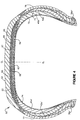
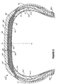
- FIGURE 1 a cross section of a typical, prior art low-profile pneumatic radial runflat tire 10 is illustrated.
- the tire 10 has a tread 12, a belt structure 14, a pair of sidewall portions 16,18, a pair of bead regions 20a,20b and a carcass structure 22.
- Belt structure 14 consists of two belts 24,26 and a fabric overlay 28 deployed between the bottom portion of tread 12 and the upper parts of the belt structure.
- the fabric overlay 28 is applied by conventional means such as by helically winding a cord reinforced ribbon.
- the carcass 22 includes a first ply 30 and second ply 32, a gas-impervious inner liner 34, a pair of beads 36a,36b, a pair of bead filler apexes 38a,38b, a first pair of inserts 40a,40b, and a second pair of inserts 42a,42b.
- the first or innermost insert 40a,40b is located between the inner liner 34 and the first ply 30, and the second insert 42a, 42b is located between the first ply 30 and second ply 32.
- Fabric overlay 28 is disposed beneath, or radially inward of, tread 12 and on top of, or radially outward from, belt structure 14.
- the reinforced sidewall portions 16,18 of carcass structure 22 give the tire 10 a limited runflat capability.
- the structural reinforcement in the sidewall area of the tire 10 substantially increases the overall thickness of the sidewall portions 16,18.
- This generalized prior art runflat tire design shows the more or less uniformly thickened sidewalls that characterize runflat tire designs. Such insert-reinforced sidewalls are necessary to support the tire's load with minimal sidewall deformation when the tire 10 is in an underinflated or uninflated state. Such runflat tire designs provide reasonable vehicle handling and performance under conditions of full inflation, and they yield reasonable runflat tire life and vehicle handling when the tire is underinflated or uninflated. Runflat tires generally weigh more than equivalent non-runflat-capable tires, because of the additional weight of the reinforcement material in the sidewalls; this additional weight is greater in high-profile runflat tires than in low-profile runflat tires.
- FIGURE 2a shows a fragmentary schematic of a normally inflated prior art tire, such as illustrated in FIGURE 1, with its tread 12 in contact with the ground 13.
- the flattening of the tread 12, in the region where it contacts the ground 13, induces bending stresses in the tread and its underlying components, including belt structure 14, overlay fabric 28, belts 24,26, radial plies 30,32, and inner liner 34. More specifically, the bending stresses derive from the flattening of the tread 12 from the as-molded and/or the as-inflated lateral curvature of tread and its underlying structures. These bending stresses induce tensile stresses in the radially inward structures beneath tread 12, such as the inner liner 34 and the radial plies 30,32. Corresponding compressive stresses are induced in the elastomeric material of tread 12 and such underlying structures as the fabric overlay 28 and portions of the belt structure 14.
- FIGURE 2b illustrates the upward buckling of tread 12 of the uninflated prior art runflat tire 10 in the region where the load-bearing tread contacts the flat road surface 13.
- the upward buckling of the central tread region corresponds to the formation of bending stresses in the central portions of tread 12 and its underlying structures.
- the bending stresses in the tread 12 during runflat operation, as illustrated in FIGURE 2b, are greater than those associated with simple flattening of the tread during normal-inflated operation, as illustrated in FIGURE 2a.
- FIGURE 3 is a fragmentary schematic detail (not in exact proportion) of the belts 24,26, plies 30,32, inner liner 34 and fabric overlay 28 as they would appear within the upward-buckled central portion (shown in FIGURE 2b) of the tread 12 of the prior art tire.
- the neutral bending axis A-A shown in FIGURE 3 is shown located in a plausible relationship with respect to the fabric overlay 28, belts 24,26, plies 30,32 and inner liner 34.
- tread 12 which lie above the neutral axis A-A -i.e., radially inward of the tread 12 -- will experience tensile loading, while those structures located below the neutral axis A-A, i.e., closer to inner liner 34, will experience compressive loading in an underinflated or uninflated tire.
- the location of neutral axis A-A in relation to belts 24,26 is approximate, taking into account the tensile-stress-bearing capabilities of radial plies 30,32 and the compressive-stress-bearing capabilities of the belts 24,26.
- the neutral axis A-A is shown to be located within belt 24 purely as an approximation of where it would lie given the relative greater modulus of elasticity of the steel cords in belts 24,26 compared to the modulus of the cords that reinforce the plies 30,32.
- FIGURE 4 shows a pneumatic, radial ply, runflat tire 50 according to the present invention.
- Tire 50 has the same general sidewall construction as that of the prior art runflat tire 10 shown in FIGURE 1.
- One of the inventive features of tire 50 in FIGURE 4 is the addition of a tensile-stress-bearing, cord-reinforced fabric layer 59, deployed between the inner liner 74 and the radially innermost radial ply 70.
- Another inventive feature of tire 50 is a compression-stress-bearing incompressible layer 66 which, in the specific illustration of FIGURE 4, is shown deployed above, or radially outward of, the belt structure 56 and beneath, or radially inward of, fabric overlay 53.
- primed and double primed numbers represent structural elements which are substantially identical to structural elements represented by the same unprimed number.
- FIGURE 4 the width of the compression-stress-bearing reinforcement 66 is generally the same or less than that of the belt structure 56.
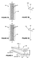
- FIGURE 5a is a fragmentary schematic cross-sectional view of tire 50 showing the circumferentially deployed belt reinforcement 66, as it would appear if the tread and other overlying structures were removed.
- Belt reinforcement 66 is constructed of a plurality of wire or metal cords 75, as discussed in more detail below.
- FIGURE 5b shows the metal cord angle MCA of incompressible metal cords 75 with respect to the equatorial plane EP of tire 50.
- FIGURE 5c is a fragmentary schematic cross-sectional view of tire 50 showing the circumferentially deployed fabric reinforcement 59, as it would appear if the tread and plies and other overlying structures were removed.
- Fabric reinforcement 59 is constructed of high-modulus cords 79 as discussed in more detail below.
- FIGURE 5d shows the fabric cord angle FCA of the high-modulus cords 79 with respect to the equatorial plane EP of tire 50. The practice of the inventive concept will become evident in the description below.
- one of the two inventive features incorporated in tire 50 is the compression-stress-bearing reinforcement 66, circumferentially deployed, in the instance of FIGURE 4, on top of, or radially outward from, belt structure 56.
- the belt reinforcement can serve generally the same operational function if it is placed between the belts 67,68 of the belt structure 56, or radially inward of the belt structure and radially outward of the ply structure 58 comprising plies 70,72.
- a second of the inventive features, as shown in FIGURE 4, is the tensile-stress-bearing fabric layer 59 which is circumferentially deployed, in the embodiment illustrated in FIGURE 4, immediately radially inward of the ply structure 58 and immediately radially outward of the inner liner 74.
- the fabric reinforcement In specific reference to the location of the tensile-stress-bearing fabric reinforcement 59, it is also within the terms of the invention for the fabric reinforcement to serve generally the same operational function when placed between the plies 70,72 of ply structure 58, or immediately radially outward of the ply structure and radially inward of the belt structure 56 comprising belts 67,68.
- FIGURE 2b shows a cross-sectional view of the upward buckled tread 12 of the prior art tire 10 when it is operated in an uninflated condition.
- FIGURE 3 shows a close-up view of the central-most portion of the upward-buckled tread 12.
- the neutral bending axis A-A in FIGURE 3 is shown located close to the interface between the high-modulus belt structure 14 comprising belts 24,26 and the ply structure 58.
- the present invention gives increased lateral and circumferential rigidity to the tread 12, thereby increasing the tread's resistance to buckling, and the structures underlying the tread during runflat operation.
- the method and structures of the present invention include incorporating either one or more high-modulus, tensile-load-bearing reinforcements 59 within or adjacent to the ply structure 58 and/or one or more high-modulus compressive-stress-bearing reinforcements 66 within or adjacent to belt structure 56 underlying the tread 52.
- the respective tensile-load-bearing and compressive-load-bearing reinforcing layers are deployed in the region adjacent to the neutral bending axis A-A, as shown in FIGURE 3. More specifically, as shown in FIGURE 4, one or more high-modulus, tensile-stress-bearing reinforcements or layers 59 are deployed in the region adjacent to the neutral bending axis A-A (on the side of the inner liner 34 in FIGURE 3) where tensile stresses are produced during buckling of the tread 12.
- one or more high-modulus, compressive-stress-bearing reinforcements or layers 66 are deployed in the region adjacent to the neutral axis A-A (on the side of the overlay 28 in FIGURE 3) where compressive stresses are produced during upward buckling of the tread.
- a second mechanism by which to stiffen the tread 12 involves the separation between the tension-bearing reinforcements 59 and the compression-bearing reinforcements 66.
- This separation is, in the present invention, brought about by the simple addition of reinforcement layers to the respective compression-stress and tensile-stress regions adjacent to the neutral bending axis A-A, as shown in FIGURE 3.
- FIGURE 6 shows an I-beam 80, supported at its ends by support elements A and B.
- I-beam 80 is shown supporting a central load L, which is such that the upper flange 82 of the I-beam is in compression, while the lower flange 84 is in tension.
- the flanges 82,84 are separated from one another by web 86.
- the tread 12 of the prior art tire 10 could be made stiffer and more resistant to buckling if the tension-bearing plies 30,32 and the compression-bearing belts 24,26 were both to be increased in strength (corresponding to thicker flanges 82,84 in FIGURE 6) and separated farther from one another (corresponding to a wider web 86 in FIGURE 6).
- the present invention achieves tread stiffening, or resistance to buckling under runflat conditions, by the addition of one or the other or both of the belt reinforcements 66, which resists compressive strain deformation, and the fabric reinforcement 59, which resists tensile strain deformation.
- the respective belt and fabric reinforcements 66,59 correspond to the I-beam flanges 82,84.
- the additional thickness of the tread 52 and its underlying carcass structure 60 and belt structure 56, plus the compressive reinforcement layer 66 and tensile reinforcement layer 59, give a greater thickness to the carcass structure and belt structure, which additional thickness corresponds, in the I-beam analogy, to the rigidity-inducing benefits of increasing the width W of the web 86 of I-beam 80 shown in FIGURE 6.
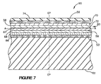
- FIGURE 7 shows a fragmentary cross-sectional view of a segment of tread 52 and underlying carcass 90 in the region of the equatorial plane EP.
- Carcass segment 90 comprises inner liner 74, tensile-stress-bearing fabric layer 59, ply structure 58 (with plies 70,72), belt structure 56 (with belts 67,68), compressive-stress-bearing layer 66, and fabric overlay 53.
- FIGURES 4 and 7 the compression-stress-bearing reinforcing layer 66 is shown located radially outward of belt structure 56 which comprises belts 67,68.
- the circumferentially deployed reinforcing layer 66 is constructed from incompressible, high-modulus material such as wire or metal cords 75, as shown in FIGURE 5a.
- FIGURE 5b shows the metal cord angle MCA of the metal wires or cords 75 with respect to the equatorial plane EP of tire 50.
- the cord angle MCA is 45 degrees to 85 degrees, and most preferably about 80 degrees with respect to the EP.
- the cord angles as defined herein include both the right and left or plus and minus directions.
- FIGURE 7 shows a plausible location for the neutral bending axis A-A of a flat carcass segment 60 in the-region of the tire's equatorial plane EP.
- belt reinforcement layer 66 in the location shown in FIGURES 4 and 7, has a mechanical advantage in resisting upward buckling of the central portion of the tread 52 during runflat operation.
- the inventors recognize that more than one compression-stress-bearing layer 66 would correspondingly increase the lateral and circumferential rigidity of tread 52 with respect to upward buckling during runflat operation of tire 50.
- the inventors also recognize the potential for tailoring the lateral rigidity of tread 52 by means of deploying the one or more compressive-stress-bearing layers 66 between the belts 67,68 of the belt structure 56, or radially inward of the belt structure to further minimize the effect on inflated tire performance, or by distributing two or more reinforcement layers among the belts 67,68.
- tensile-stress-bearing reinforcing fabric layer 59 is shown located radially inward of the ply structure 58, which comprises radial plies 70,72.
- the circumferentially deployed fabric reinforcing layer 59 is constructed from fabric that is reinforced with high-modulus cords made from materials of the type that come from the family of materials that include aramid, rayon, and polyester.
- FIGURE 5c shows the circumferential fabric layer 59 and its reinforcing cords 79.
- FIGURE 5d shows the fabric cord angle FCA of the reinforcing cords 79 with respect to the equatorial plane EP of tire 50.
- the cord angle FCA is 45 degrees to 85 degrees, and most preferably about 80 degrees, each with respect to the EP.
- the inventors recognize that more than one tensile-stress-bearing layer 59 would correspondingly increase the lateral and circumferential rigidity of tread 52 with respect to upward buckling during runflat operation of tire 50.
- the inventors also recognize the potential for tailoring the lateral rigidity of tread 52 by means of deploying the one or more tensile-stress-bearing fabric layers 59 between the plies 70,72 of the ply structure 58, or radially outward of the ply structure, or by distributing two or more reinforcement layers among the plies 70,72.
- FIGURE 8 is a cross-sectional view of one embodiment of the present invention as used in a pneumatic radial ply runflat tire 100 in which two compressive-stress-reinforcing layers 66',66'' are deployed such that one reinforcing layer 66'' of them is located radially outward of the radially outer-most belt 68' while the other 66' is located between the belts 67' and 68'. Additionally, two tensile-stress-bearing fabric reinforcement layers 59',59'' are deployed such that one fabric layer 59' is located radially inward of the radially inner-most ply 72' while the other fabric layer 59'' is located between the two plies 70' and 72'.
- the reinforcing cords of the adjacent reinforcement layers are in crossed relation to each other. The angles of the cords are disposed at the same angles as the cords of a single reinforcement layer as previously defined.
- tread buckling (which is also known as "tread lift") associated with runflat tires when they are operated in the runflat mode.
- the reinforced sidewalls 16,18 of a prior art uninflated runflat tire 10 of the type shown in FIGURE 1 tend to buckle axially outwards in such a way as to transmit upward-directed bending stresses to the tread 12 and underlying structures such that the central portion of the tread has reduced to zero contact with the road.
- Upward buckling of the tread can have adverse effects upon vehicle handling in the runflat mode, especially during high-speed operation.
- the cyclical flexing of the tread during runflat operation tends to cause heating of the tread material, especially during high-speed operation, which can cause accelerated deterioration of the tire structure in the region of the tread, thereby reducing the runflat tire's operating life in the runflat mode.
- a hypothetically perfect runflat tire would be able to maintain the central portion of its tread in the same degree of road contact during runflat operation as during fully inflated operation.
- the incorporation of the one or more compressive-stress-bearing metal reinforcements 66',66'' in the region of the belt structure 56' (FIGURE 8) and the incorporation of the one or more tensile-stress-bearing fabric reinforcements 59',59'' in the region adjacent to or within the ply structure 58' work to increase the lateral and circumferential rigidity of the tread 52'.
- FIGURE 4 there is illustrated a first embodiment of the invention within a runflat radial ply tire 50.
- a runflat radial ply tire 50 Such an embodiment would have potential for runflat use in high-performance sports type vehicles or light trucks, if provided as a low-aspect-ratio runflat radial ply runflat pneumatic tire, or if provided as a high-aspect-ratio tire for luxury-type vehicles, high-standing sport-utility vehicles, and some light trucks.
- Tire 50 contains two belts 67,68, two plies 70,72, a belt reinforcing layer 66 and a fabric reinforcing layer 59.
- Fabric reinforcement layer 59 has reinforcing cords 79 that are oriented more or less laterally across the crown region of tire 50.
- Belt reinforcement layer 66 has metal reinforcing cords 75 also oriented more or less laterally across the crown region of tire 50.
- the metal belt reinforcement layer 66 contributes compressive strain resistance to the belt structure 56.
- the fabric reinforcement layer 59 contributes tensile strain resistance to the ply structure 58.
- the improved lateral rigidity of the tread gives better vehicle handling and stability during high-speed runflat operation as well as increased runflat tire life.
- a second embodiment is envisioned in which this invention is incorporated within a radial ply runflat tire, as also shown in FIGURE 4, having at least one radial ply 70 or 72 which is reinforced by essentially inextensible fibers or cords made of metal such as steel, such as is disclosed in U.S. Patent Application 08/865,489, and in which the aspect ratio of the tire can be low or high or intermediate between the maximum and minimum values of aspect ratios for runflat tires.
- FIGURE 8 A third embodiment is shown in FIGURE 8, where two compressive-stress-reinforcing layers 66',66'' are deployed such that one is located radially outward of the radially outer-most belt 68' while the other is located between the belts 67' and 68'.
- This embodiment also contains two tensile-stress-bearing fabric reinforcement layers 59',59" which are deployed such that one fabric layer 59'' is located radially inward of the radially inner-most ply 70' while the other fabric layer 59' is located between the two plies 70',72'.
- the reinforcing cords of the adjacent reinforcement layers are in crossed relation to each other. The angles of the cords are disposed at the same angles as the cords of a single reinforcement layer, as previously defined.
Description
Claims (10)
- A pneumatic radial ply runflat tire (50; 100) having a tread (52; 52'), a carcass (60; 60') with two sidewalls (77, 78; 77', 78') and two inextensible annular beads (36a', 36b'; 36a", 36b"), a radial ply structure (58; 58'), one or more sidewall reinforcing inserts (40a', 40b', 42a', 42b'; 40a", 40b", 42a", 42b"), and a belt structure (56; 56') located between the tread and the radial ply structure;
and at least one circumferentially deployed compression-stress-bearing belt reinforcing layer (66; 66', 66") located in the region of the belt structure (56; 56') and having reinforcing metal cords (75) being aligned at an angle of between 45 and 85 degrees with respect to the equatorial plane of the tire;
and at least one circumferentially deployed tensile-stress-bearing fabric reinforcing layer (59; 59', 59") located in the region of the radial ply structure (58; 58') and having reinforcing fabric cords (79) being aligned at an angle of between 45 to 85 degrees with respect to the equatorial plane of the tire. - The tire (50) of claim 1 in which the width of the at least one circumferentially deployed belt reinforcing layer (66) and the at least one circumferentially deployed fabric reinforcing layer (59) are approximately equal to the width of the belt structure (56).
- The tire (50) of claim 1 wherein the at least one belt reinforcing layer (66) has reinforcing metal cords (75) being aligned at about 80 degrees with respect to the equatorial plane of the tire.
- The tire (50) of claim 1 wherein the fabric reinforcing layer (59) is deployed between the innerliner (74) and the radially innermost radial ply (70).
- The tire (50) of claim 1 wherein the at least one fabric reinforcing layer (59) has reinforcing cords (79) aligned at about 80 degrees with respect to the equatorial plane of the tire.
- The tire (50) of claim 5 in which at least one of the radial plies (70,72) of the radial ply structure (58) is reinforced with inextensible metal cords.
- The tire (50) of claim 1 wherein the fabric reinforcing layer (59) is constructed from fabric reinforced with high-modulus cords made from aramid, rayon or polyester.
- The tire (50) of claim 1 wherein the belt reinforcing layer (66) is deployed radially outward of the belt structure (56) and radially inward of a fabric overlay (53).
- The tire (50) of claim 1 wherein the belt reinforcing layer (66) is placed between the belts (67,68) of the belt structure (56).
- The tire (50) of claim 1 wherein the fabric reinforcing layer (59) is placed immediately radially outward of the radial ply structure (58) and radially inward of the belt structure (56) comprising two belts (67,68).
Applications Claiming Priority (1)
| Application Number | Priority Date | Filing Date | Title |
|---|---|---|---|
| PCT/US1998/014452 WO2000002740A1 (en) | 1998-07-10 | 1998-07-10 | Thread reinforcement means for extended mobility tire |
Publications (2)
| Publication Number | Publication Date |
|---|---|
| EP1097048A1 EP1097048A1 (en) | 2001-05-09 |
| EP1097048B1 true EP1097048B1 (en) | 2003-01-02 |
Family
ID=22267467
Family Applications (1)
| Application Number | Title | Priority Date | Filing Date |
|---|---|---|---|
| EP98935626A Expired - Lifetime EP1097048B1 (en) | 1998-07-10 | 1998-07-10 | Tread reinforcement means for extended mobility tire |
Country Status (6)
| Country | Link |
|---|---|
| EP (1) | EP1097048B1 (en) |
| JP (1) | JP4559624B2 (en) |
| KR (1) | KR100631265B1 (en) |
| AU (1) | AU8482798A (en) |
| DE (1) | DE69810517T2 (en) |
| WO (1) | WO2000002740A1 (en) |
Families Citing this family (10)
| Publication number | Priority date | Publication date | Assignee | Title |
|---|---|---|---|---|
| US6701987B1 (en) | 1999-04-12 | 2004-03-09 | The Goodyear Tire & Rubber Company | Tread stiffening support ribs for runflat tire |
| EP1326755B1 (en) * | 2000-10-10 | 2007-05-02 | Société de Technologie Michelin | Tire having more carcass layers in sidewall than in bead |
| FR2864469A1 (en) * | 2003-12-30 | 2005-07-01 | Michelin Soc Tech | Pneumatic tyre designed to run when deflated has self-supporting side walls reinforced by inserts of rigid rubber composition in zones |
| EP1733901A1 (en) * | 2005-06-16 | 2006-12-20 | Societe de Technologie Michelin | Extended-mobility tire having separated carcass portions in summit |
| FR2900097B1 (en) * | 2006-04-20 | 2010-10-08 | Michelin Soc Tech | PNEUMATIC TIRE WITH EXTENDED MOBILITY COMPRISING TWO REINFORCING STRUCTURES AND A LOW SOFT ZONE. |
| JP5046556B2 (en) * | 2006-05-19 | 2012-10-10 | 株式会社ブリヂストン | Safety tire |
| JP5046555B2 (en) * | 2006-05-19 | 2012-10-10 | 株式会社ブリヂストン | Safety tire |
| KR100779310B1 (en) * | 2006-06-30 | 2007-11-23 | 금호타이어 주식회사 | Pneumatic tire with strengthened bead |
| JP5321104B2 (en) * | 2009-02-05 | 2013-10-23 | 横浜ゴム株式会社 | Pneumatic tire |
| JP2018505096A (en) | 2015-02-11 | 2018-02-22 | ブリヂストン アメリカズ タイヤ オペレーションズ、 エルエルシー | Run flat tire with sidewall reinforcement insert |
Family Cites Families (8)
| Publication number | Priority date | Publication date | Assignee | Title |
|---|---|---|---|---|
| CA1051330A (en) * | 1974-10-09 | 1979-03-27 | John T. Alden | Pneumatic tire |
| JPS53126601A (en) * | 1977-04-08 | 1978-11-06 | Bridgestone Corp | Pneumatic safety tire |
| FR2425334A1 (en) * | 1978-05-11 | 1979-12-07 | Kleber Colombes | Sub-tread reinforcement of run-flat pneumatic tyres - using rubber supported hoop plies for a high lateral tread stiffness wt. ratio |
| FR2460218A2 (en) * | 1979-06-28 | 1981-01-23 | Kleber Colombes | Ply format for sub-tread reinforcement of a self:supporting tyre - modified to improve delamination resistance of sub-tread ply borders |
| IT1245271B (en) * | 1990-09-14 | 1994-09-13 | Pirelli | SELF-SUPPORTING CARCASS FOR MOTOR VEHICLE TIRES |
| JP3645277B2 (en) * | 1992-12-24 | 2005-05-11 | 株式会社ブリヂストン | Pneumatic tire |
| ES2184864T3 (en) * | 1995-06-26 | 2003-04-16 | Bridgestone Corp | RADIAL TIRE. |
| JP4308329B2 (en) * | 1997-05-29 | 2009-08-05 | ザ グッドイヤー タイヤ アンド ラバー カンパニー | Run-flat tire with improved non-inflating handling |
-
1998
- 1998-07-10 KR KR1020017000180A patent/KR100631265B1/en not_active IP Right Cessation
- 1998-07-10 DE DE69810517T patent/DE69810517T2/en not_active Expired - Lifetime
- 1998-07-10 JP JP2000558987A patent/JP4559624B2/en not_active Expired - Fee Related
- 1998-07-10 WO PCT/US1998/014452 patent/WO2000002740A1/en active IP Right Grant
- 1998-07-10 EP EP98935626A patent/EP1097048B1/en not_active Expired - Lifetime
- 1998-07-10 AU AU84827/98A patent/AU8482798A/en not_active Abandoned
Also Published As
| Publication number | Publication date |
|---|---|
| WO2000002740A1 (en) | 2000-01-20 |
| KR100631265B1 (en) | 2006-10-02 |
| DE69810517T2 (en) | 2003-09-11 |
| JP2002520207A (en) | 2002-07-09 |
| JP4559624B2 (en) | 2010-10-13 |
| DE69810517D1 (en) | 2003-02-06 |
| KR20010053410A (en) | 2001-06-25 |
| AU8482798A (en) | 2000-02-01 |
| EP1097048A1 (en) | 2001-05-09 |
Similar Documents
| Publication | Publication Date | Title |
|---|---|---|
| US6719029B2 (en) | Tire wall gauges to optimize runflat tire ride comfort | |
| US6923233B1 (en) | Runflat tire with sawtooth shaped insert | |
| EP1097048B1 (en) | Tread reinforcement means for extended mobility tire | |
| EP1242256B1 (en) | Variable-stiffness wedge inserts for runflat tires | |
| US6701987B1 (en) | Tread stiffening support ribs for runflat tire | |
| US20030145931A1 (en) | Underlay structure for increased crown stiffening | |
| US6561245B1 (en) | Thread reinforcement means for extended mobility tire | |
| US7104301B2 (en) | Discontinuous ply for runflat tire construction | |
| US6338374B1 (en) | Runflat tire with fabric underlay and tread insert | |
| EP1181161B1 (en) | Reinforced wedge-insert construction for extended mobility tires | |
| EP1089885B1 (en) | Tread and sidewall construction for runflat tire | |
| EP1022162B1 (en) | Tire with improved run-flat design | |
| US6536495B1 (en) | Tread stiffening for two ply runflat tire | |
| WO1999048710A1 (en) | Fabric underlay and tread insert for improved tread rigidity of runflat tire | |
| US6550509B1 (en) | Tread and sidewall construction for runflat tire | |
| EP1198360B1 (en) | Fabric support for metal reinforced inner ply of runflat tire | |
| US6814120B1 (en) | Fabric support for metal reinforced inner ply of runflat tire | |
| EP1156937B1 (en) | Discontinuous ply for runflat tire construction | |
| EP1094956B1 (en) | Runflat tire having a fabric underlay for improving tread circumferential and meridional rigidity and method of constructing | |
| WO2000020236A1 (en) | Improved construction for runflat tire | |
| EP1222079B1 (en) | Runflat tire with sawtooth shaped insert | |
| EP1171320B1 (en) | Tread stiffening support ribs for runflat tire | |
| EP1126984B1 (en) | Tread stiffening for two-ply runflat tire |
Legal Events
| Date | Code | Title | Description |
|---|---|---|---|
| PUAI | Public reference made under article 153(3) epc to a published international application that has entered the european phase |
Free format text: ORIGINAL CODE: 0009012 |
|
| 17P | Request for examination filed |
Effective date: 20010212 |
|
| AK | Designated contracting states |
Kind code of ref document: A1 Designated state(s): DE FR IT |
|
| 17Q | First examination report despatched |
Effective date: 20011009 |
|
| GRAG | Despatch of communication of intention to grant |
Free format text: ORIGINAL CODE: EPIDOS AGRA |
|
| GRAG | Despatch of communication of intention to grant |
Free format text: ORIGINAL CODE: EPIDOS AGRA |
|
| GRAH | Despatch of communication of intention to grant a patent |
Free format text: ORIGINAL CODE: EPIDOS IGRA |
|
| GRAH | Despatch of communication of intention to grant a patent |
Free format text: ORIGINAL CODE: EPIDOS IGRA |
|
| GRAA | (expected) grant |
Free format text: ORIGINAL CODE: 0009210 |
|
| AK | Designated contracting states |
Kind code of ref document: B1 Designated state(s): DE FR IT |
|
| REF | Corresponds to: |
Ref document number: 69810517 Country of ref document: DE Date of ref document: 20030206 Kind code of ref document: P |
|
| ET | Fr: translation filed | ||
| PLBE | No opposition filed within time limit |
Free format text: ORIGINAL CODE: 0009261 |
|
| STAA | Information on the status of an ep patent application or granted ep patent |
Free format text: STATUS: NO OPPOSITION FILED WITHIN TIME LIMIT |
|
| 26N | No opposition filed |
Effective date: 20031003 |
|
| PGFP | Annual fee paid to national office [announced via postgrant information from national office to epo] |
Ref country code: IT Payment date: 20100723 Year of fee payment: 13 Ref country code: FR Payment date: 20100813 Year of fee payment: 13 Ref country code: DE Payment date: 20100730 Year of fee payment: 13 |
|
| REG | Reference to a national code |
Ref country code: FR Ref legal event code: ST Effective date: 20120330 |
|
| PG25 | Lapsed in a contracting state [announced via postgrant information from national office to epo] |
Ref country code: DE Free format text: LAPSE BECAUSE OF NON-PAYMENT OF DUE FEES Effective date: 20120201 Ref country code: FR Free format text: LAPSE BECAUSE OF NON-PAYMENT OF DUE FEES Effective date: 20110801 |
|
| REG | Reference to a national code |
Ref country code: DE Ref legal event code: R119 Ref document number: 69810517 Country of ref document: DE Effective date: 20120201 |
|
| PG25 | Lapsed in a contracting state [announced via postgrant information from national office to epo] |
Ref country code: IT Free format text: LAPSE BECAUSE OF NON-PAYMENT OF DUE FEES Effective date: 20110710 |