EP1096846A1 - Inspection method and inspection apparatus for printed circuit boards - Google Patents
Inspection method and inspection apparatus for printed circuit boards Download PDFInfo
- Publication number
- EP1096846A1 EP1096846A1 EP00123253A EP00123253A EP1096846A1 EP 1096846 A1 EP1096846 A1 EP 1096846A1 EP 00123253 A EP00123253 A EP 00123253A EP 00123253 A EP00123253 A EP 00123253A EP 1096846 A1 EP1096846 A1 EP 1096846A1
- Authority
- EP
- European Patent Office
- Prior art keywords
- board
- coordinate positions
- amount
- holding members
- correction
- Prior art date
- Legal status (The legal status is an assumption and is not a legal conclusion. Google has not performed a legal analysis and makes no representation as to the accuracy of the status listed.)
- Withdrawn
Links
Images




Classifications
-
- G—PHYSICS
- G01—MEASURING; TESTING
- G01N—INVESTIGATING OR ANALYSING MATERIALS BY DETERMINING THEIR CHEMICAL OR PHYSICAL PROPERTIES
- G01N21/00—Investigating or analysing materials by the use of optical means, i.e. using sub-millimetre waves, infrared, visible or ultraviolet light
- G01N21/84—Systems specially adapted for particular applications
- G01N21/88—Investigating the presence of flaws or contamination
- G01N21/95—Investigating the presence of flaws or contamination characterised by the material or shape of the object to be examined
- G01N21/956—Inspecting patterns on the surface of objects
- G01N21/95607—Inspecting patterns on the surface of objects using a comparative method
-
- G—PHYSICS
- G01—MEASURING; TESTING
- G01N—INVESTIGATING OR ANALYSING MATERIALS BY DETERMINING THEIR CHEMICAL OR PHYSICAL PROPERTIES
- G01N21/00—Investigating or analysing materials by the use of optical means, i.e. using sub-millimetre waves, infrared, visible or ultraviolet light
- G01N21/84—Systems specially adapted for particular applications
- G01N21/88—Investigating the presence of flaws or contamination
- G01N21/95—Investigating the presence of flaws or contamination characterised by the material or shape of the object to be examined
- G01N21/956—Inspecting patterns on the surface of objects
- G01N2021/95638—Inspecting patterns on the surface of objects for PCB's
Definitions
- This invention relates to an inspection method and inspection apparatus wherein a board that has been conveyed to the inspection position is photographed with a line sensor camera and inspected.
- One method for performing such inspections is the method of inspecting by using a line sensor camera to photograph boards that have been conveyed to an inspection position.
- FIGs. 7 to 10 A conventional inspection apparatus is shown in Figs. 7 to 10.
- the inspection apparatus is configured such that an inspection is made by causing a line sensor camera 3 to photograph a printed circuit board 1 conveyed to an inspection position, by scanning that printed circuit board 1 in a direction (direction indicated by arrow C) along the direction of board conveyance.
- the printed circuit board 1 in the inspection position is held by a pair of rails 2 being constant in breadth and constituting a pair of holding members.
- the line sensor camera 3 is movable in the direction of arrow C by a movement shaft 8, and photographs the surface of the printed circuit board 1 through a reflecting mirror 10.
- the movement shaft 8 is sometimes caused to expand and contract or the printed circuit board 1 to expand and contract due to factors such as heat.
- a first correction mark 6e and a second correction mark 6f are provided on the side where the line sensor camera 3 starts reading and on the side where it ends reading, respectively, such that these correction marks 6e and 6f are positioned on a diagonal line passing through the board 1. Using the correction marks in these two places, any discrepancy in the movement shaft 8 or printed circuit board 1 described above is corrected.
- the ratios in the X axis direction and the Y axis direction are both valued 1, it can be judged that there is no expansion or contraction in the movement shaft 8 or the printed circuit board 1.
- the ratio is other than 1, however, it is judged that there is expandsion or contraction in the movement shaft 8 and/or printed circuit board 1, whereupon adjustments are made to respective coordinate positions in an image so that the recognized positions of the correction marks become the taught values, and the position of the printed circuit board 1 is also adjusted.
- respective X-coordinate and Y-coordinate values in the recognized image are divided by ⁇ x and ⁇ y to produce corrected values so that a corrected image can be presented.
- the line sensor camera 3 When the printed circuit board 1 is photographed two times with the line sensor camera 3, for example, first, as shown in Fig. 10(a-1), the line sensor camera 3 is moved from a first scan start position 5c in the direction indicated by arrow E1, whereupon a first scan area 7a wherein a first inspection point 11a is provided is photographed.
- the printed circuit board 1 is moved in the direction indicated by arrow E2 by the screw shaft, and a second scan area 7b wherein a second inspection point 11b is provided is photographed from a second scan start position 5d.
- Fig. 10(b-1) where photographing is done in the same manner as shown in Fig. 10(a-1), shows a reference position for moving the printed circuit board 1 with the screw shaft, so that the first scan start position 5c and the first scan start position 5e are at the same position, and there is no discrepancy between the first scan area 7a and the first scan area 7c photographed by the line sensor camera 3.
- the distance from the second scan start position 5d to the second correction mark 6f as shown in Fig. 10(a-2) differs from the distance from the second scan start position 5f to the second correction mark 6h as shown in Fig. 10(b-2).
- the distance from the second scan start position 5d to the second inspection point 11b as shown in Fig. 10(a-2) differs from the distance from the second scan start position 5f to the second inspection point 11d as shown in Fig. 10(b-2). Accordingly, overall dislocation has occurred between the image including the first scan area 7c and the second scan area 7d as shown in Fig. 10(b-3), and the image including the first scan area 7s and the second scan area 7b as shown in Fig. 10(a-3).
- the inspection method of the present invention is characterized in that a to-be-inspected board is moved laterally and an amount of movement of holding members of the board is corrected based on an amount of positional discrepancy of the board.
- large boards can be inspected, and high-precision inspections can be effected.
- the inspection apparatus of the invention is characterized in that correction marks are provided on the holding members for holding the board.
- the inspection method of the present invention can be easily implemented.
- the inspection, method described in claim 1 of the present invention is a method for inspecting a to-be-inspected board by photographing the board that has been conveyed to an inspection position, in which a pair of holding members constituted of a pair of rails for holding the board are moved to move the board in a direction crossing a scanning direction of a photography unit and the board that has been positioned is scanned by the photography unit along the direction of said conveyance of the board, the inspection method comprising: reading coordinate positions of correction marks applied to said holding members by said photography unity computing an amount of positional discrepancy of the board by comparing coordinate positions of correction marks previously set with the coordinate positions of correction marks having been read; and when there are discrepancies between said two kinds of coordinate positions, carrying out said photographing after correcting an amount of movement of the holding members based on said amount of positional discrepancy of the board.
- the inspection method according to claim 2 of the present invention is a method for inspecting a to-be-inspected board by photographing the board that has been conveyed to an inspection position, in which a pair of holding members constituted of a pair of rails located in an opposed relation to each other for holding the board are moved to move the board in a direction crossing a scanning direction of a photography unit and the board that has been positioned is scanned by the photography unit along the direction of said conveyance of the board, the inspection method comprising: reading a coordinate position of a first correction mark applied to one of the holding members by said photography unit; moving said holding members and reading a coordinate position at a second correction mark applied to the other of the holding members, said second correction mark on said the other of the holding members being on the side opposite to that of the first correction mark on said one of the holding members with the board being interposed therebetween; computing an amount of positional discrepancy of the board by comparing coordinate positions of first and second correction marks previously set with the coordinate positions of the first and second correction marks having been read; and when
- the inspection method described in claim 3 of the present invention is a method for inspecting a to-be-inspected board by photographing the board that has been conveyed to an inspection position, in which a pair of holding members constituted of a pair of rails for holding the board are moved to move the board in a direction crossing a scanning direction of a photography unit and the board that has been positioned is scanned by the photography unit along the direction of said conveyance of the board, the inspection method comprising: reading coordinate positions of correction marks applied to said board by said photography unit; computing an amount of positional discrepancy of said board by comparing coordinate positions of correction marks previously set with the coordinate positions of the correction marks having been read; and when there are discrepancies between said two kinds of coordinate positions, carrying out said photographing after correcting an amount of movement of the holding members based on said amount of positional discrepancy of the board.
- the inspection method described in claim 4 of the present invention is a method according to claim 2, wherein the first and second correction marks are provided on the side where the photography unit starts reading.
- the inspection method described in claim 5 of the present invention is a method according to claim 3, wherein a first correction mark and a second correction mark are provided on the board, said first correction mark being provided on the side where the photography unit starts reading, said second correction mark being provided on a diagonal line passing said first correction mark.
- the inspection apparatus described in claim 6 of the present invention is an apparatus for inspecting a to-be-inspected board by photographing the board that has been conveyed to an inspection position, in which a pair of holding members constituted of a pair of rails for holding the board are moved to move the board in a direction crossing a scanning direction of a photography unit and the board that has been positioned is scanned by the photography unit along the direction of said conveyance of the board, the inspection apparatus comprising: a control unit configured to read coordinate positions of correction marks applied to the holding members by the photography unit, to compute an amount of positional discrepancy of the board by comparing coordinate positions of correction marks previously set with the coordinate positions of the correction marks having been read, and when there are discrepancies between said two kinds of coordinate positions, to carry out said photographing after correcting an amount of movement of the holding members based on said amount of positional discrepancy of the board.
- the inspection apparatus 40 is comprised of two movement shafts, namely the screw shaft 4 for moving the printed circuit board 1 which has been conveyed to an inspection position, along the breadth direction of the rails 2 (direction indicated by arrow B), and a movement shaft 8 for moving a line sensor camera 3 or a photography unit along the direction of conveyance of the board (direction indicated by arrow A.).
- 9 represents a moving platform for mounting thereon the pair of rails 2, which is driven to move in the direction indicated by arrow B as the screw shaft 4 rotates; 20 a motor for rotationally driving the screw shaft 4; 21 a rotary encoder for detecting an amount of rotation of the motor 20; 22 a motor for rotationally driving the movement shaft 8; 23 a rotary encoder for detecting an amount of rotation of the motor 22; 25 a control unit for controlling the overall inspection apparatus including the motors 20 and 22; and 30 an image processing unit for processing image data photographed by the line sensor camera 3.
- the control system of the inspection apparatus 40 is configured as shown in Fig. 3.
- control unit 25 is connected with an input device 26 and CRT 31, so that an operator operates the inspection apparatus 40 by inputting instructions, information data and so on to the input device 26 while watching the CRT 31.
- Represented by 32 is a storage unit for storing therein data input from the input device 26, control programs necessary to actuate the inspection apparatus 40, control parameters, image data photographed by the line sensor camera 3 and so on.
- the printed circuit board 1 is held by the pair of rails 2 constituting a pair of holding members, and first and second correction marks 6a and 6b for the holding members are provided on the side 51 of the rails 2 where the line sensor camera 3 starts reading.
- the screw shaft 4 sometimes expands or contracts due to heat and other factors, with the passage of time, so that discrepancies can occur between coordinate positions where the first and second holding member correction marks 6a and 6b have been recognized on the rails 2 at a point of time t1, and coordinate positions where the first and second holding member correction marks 6a and 6b have been recognized on the rails 2 at another point of time t2 after a passage of a certain period of time from t1.
- a positional discrepancy occurs at the first scan start position 5a and the second scan start position 5b, respectively, and a discrepancy occurs in the first and second inspection areas 7a and 7b.
- the coordinate positions of the first and second holding member correction marks 6a and 6b are read by the line sensor camera 3, and the control illustrated by the flow chart shown in Fig. 4 is performed by the control unit 25 so that the amount of movement of the printed circuit board 1 in the direction indicated by arrow B is corrected.
- step S1 the coordinate positions of the first and second correction marks 6a and 6b are set by the input device 26 and stored in the storage unit 32.
- step S2 the motor 20 is driven to move the printed circuit board 1 in the direction of B in order to photograph the first scan area of the printed circuit board 1.
- step S3 every time one printed circuit board 1 is inspected, or once every several boards have been inspected, or when a value measured by a screw shaft temperature detector 35 for detecting temperature of the screw shaft 4 exceeds a previously set threshold value, the first correction mark 6a provided on one of the rails 2 constituting the holding members is recognized, and in step S4, according to the instruction from the control unit 25, the line sensor camera 3 is moved in the direction A to photograph the first holding member correction mark 6a, and thus photographed correction mark is subjected to image processing by the image processing unit 30 so that the position of the first holding member correction mark 6a is detected. Then, the amount of positional discrepancy between the coordinate position of the first holding member correction mark 6a detected by photography and that of the set holding member correction mark 6a is computed.
- step S5 When it is judged in step S5 that there is a discrepancy between the coordinate positions of the two kinds of the first correction marks 6a, the amount of movement of the printed circuit board 1 is corrected and the positional discrepancy of the first scan start position 5a is corrected in step S6.
- the amount of rotation of the motor 22 is detected by the encoder 23 in order that the motor 22 rotates for the same amount corresponding to the amount of positional discrepancy obtained in step S4, thereby correcting the amount of positional discrepancy and solving the problem associated with such discrepancy.
- step S5 After the corrections the amount of coordinate positional discrepancy of the first holding member correction mark is detected again in steps S3 and S4, and in step S5, it is determined whether or not there exists the positional discrepancy. This is repeated until it is determined in step S5 that there exists no more positional discrepancy.
- step S7 the line sensor camera 3 is moved, for example, from a reading start side 51 toward a reading end side 52 as shown in Fig. 1, in order to photograph the first scan area 7a of the printed circuit board 1 by the line sensor camera 3.
- the first correction mark 6c provided on the printed circuit board 1 is photographed, and its center position is obtained by image processing by the image processing unit 30.
- step S5 When it is judged in step S5 that there is no positional discrepancy, too, the printed circuit board 1 is photographed in step S7.
- step S8 according to the instruction from the control unit 25, the motor 20 is rotationally driven for an amount of movement corresponding to the distance from the previously set first holding member correction mark 6a to the second holding member correction mark 6b, and the printed circuit board 1 is moved in the direction B to a position where the second scan area is photographed.
- step S11 When it is judged in step S11 that there is a coordinate positional discrepancy with the second holding member correction mark 6b, in the same manner as in step S6, the amount of movement of the printed circuit board 1 is corrected and the positional discrepancy of the first scan start position 5a is corrected. Such corrections are repeated in steps S9 and S10, until it is judged again that there is no positional discrepancy in step S11.
- step S11 When it is judged that there is no positional discrepancy in step S11, the second scan area 7b of the printed circuit board 1 is photographed by the line sensor camera 3 in step S13. At the same time, the board correction mark 6d on the printed circuit board 1 is also photographed, and its center position is obtained through image processing by the image processing unit 30.
- step S14 the amount of discrepancies between the recognized coordinate positions of the first and second board correction marks 6c and 6d obtained in step S7 and step S13, and the coordinate positions of the board correction marks 6c and 6d previously set is computed, and in order to solve the discrepancy amount, the image of the printed circuit board including the first scan area and the second scan area combined is corrected by employing the conventional method earlier mentioned so that the board correction marks 6c and 6d appearing on the image correspond to the previously set positions.
- step S15 the corrected image of the printed circuit board is subjected to image processing and inspection judgment, thereafter the result of inspection is output.
- positional corrections can be performed to compensate for the expansion and contraction in movement shafts and in printed circuit boards caused by heat and other factors, even in inspection machines that are configured with biaxial movement shafts.
- the first and second correction marks 6a and 6b are placed in an opposed relations to each other on the rails on the side where the line sensor camera 3 starts reading, but the present invention is not limited thereto or thereby, and their set positions can be adjusted as may be expedient.
- step S1 the coordinate positions of the first and second board correction marks 6c and 6d are set by the input device 26 and stored in the storage unit 32.
- step S2 the motor 20 is driven to move the printed circuit board 1 in the direction of B in order to photograph the first scan area of the printed circuit board 1.
- step S3 every time one printed circuit board 1 is inspected, or once every several boards have been inspected, or when a value measured by a screw shaft temperature detector 35 for detecting temperature of the screw shaft 4 exceeds a previously set threshold value, the first board correction mark 6c provided on the printed circuit board is recognized, and in step S4, according to the instruction from the control unit 25, the line sensor camera 3 is moved in the direction A to photograph the first board correction mark 6c, and thus photographed correction mark is subjected to image processing by the image processing unit 30 so that the position of the first board correction mark 6c is detected. Then, the amount of positional discrepancy between the coordinate position of the first board correction mark 6c detected by photography and that of the set board correction mark 6c is computed.
- step S5 When it is judged in step S5 that there is a discrepancy between the coordinate positions of the two kinds of the first board correction marks 6c, the amount of movement of the printed circuit board 1 is corrected and the positional discrepancy of the first scan start position 5a is corrected in step S6.
- step S5 After the correction, the amount of coordinate positional discrepancy of the first board correction mark is detected again in steps S3 and S4, and in step S5, it is determined whether or not there exists the positional discrepancy. This is repeated until it is determined in step S5 that there exists no more positional discrepancy.
- the first board correction mark 6c provided on the printed circuit board 1 is photographed, and its center position is obtained by image processing by the image processing unit 30.
- step S5 When it is judged in step S5 that there is no positional discrepancy, too, the printed circuit board 1 is photographed in step S7.
- step S8 according to the instruction from the control unit 25, the motor 20 is rotationally driven for an amount of movement in the direction B corresponding to the distance from the previously set first board correction mark 6c to the second board correction mark 6d, and the printed circuit board 1 is moved in the direction B to a position where the second scan area is photographed.
- step S9 according to the instruction from the control unit 25, the line sensor camera 3 is moved in the direction A, and the second board correction mark 6d is photographed. And in step S10, the amount of positional discrepancy between the coordinate position of the second board correction mark 6d which has been read and the coordinate position of the previously set second board correction mark 6d is computed.
- step S11 When it is judged in step S11 that there is a coordinate positional discrepancy with the second board correction mark 6d, in the same manner as in step S6, the amount of movement of the printed circuit board 1 is corrected and the positional discrepancy of the first scan start position 5a is corrected. Such corrections are repeated in steps S9 and S10, until it is judged again that there is no positional discrepancy in step S11.
- step S11 When it is judged that there is no positional discrepancy in step S11, the second scan area 7b of the printed circuit board 1 is photographed by the line sensor camera 3 in step S13. At the same time, the board correction mark 6d on the printed circuit board 1 is also photographed, and its center position is obtained through image processing by the image processing unit 30.
- step S14 the amount of discrepancies between the recognized coordinate positions of the first and second board correction marks 6c and 6d obtained in step S7 and step S13, and the coordinate positions of the board correction marks 6c and 6d previously set is computed, and in order to solve the discrepancy amount, the image of the printed circuit board including the first scan area and the second scan area combined is corrected by employing the conventional method earlier mentioned so that the board correction marks 6c and 6d appearing on the image correspond to the previously set positions.
- positional corrections can be performed to compensate for the expansion and contraction in movement shafts and in printed circuit boards due to heat and/or other factors, even in inspection machines that are configured with two movement shafts as in the first embodiment described earlier.
- the positional discrepancy of the screw shaft is corrected using the same first and second correction marks as used in the conventional expansion and contraction correction method, but the present invention is not limited thereto or thereby, nor is there any particular limitation on the positions of the first and second board correction marks used in the correction shown in Fig. 5
- the coordinate positions or correction marks applied to holding members are read by a line sensor camera, an amount of positional discrepancy of a board is computed by comparing previously set coordinate positions of the correction marks with coordinate positions of the read correction marks, and when there are discrepancies between the two kinds of coordinate positions, photographing noted earlier is performed after correcting an amount of movement of the holding members based on the amount of positional discrepancy of the board, whereby it is possible to inspect a large-size board by laterally moving the board and photographing the same for a plural number of times before and after the lateral moving, and it is also possible to achieve high-precision inspection.
- the inspection method of the present invention can be easily implemented by providing a control unit configured so that the coordinate positions of the correction marks applied to the holding members are read by the line sensor camera, an amount of positional discrepancy of the board is computed by comparing the coordinate positions of the previously set correction marks with the coordinate positions of the read correction marks, and when there are coordinate-positional discrepancies between the two kind of correction marks, the photographing is performed after correcting the amount of movement of the holding members based on the amount of positional discrepancy of the board.
Landscapes
- General Health & Medical Sciences (AREA)
- Health & Medical Sciences (AREA)
- Life Sciences & Earth Sciences (AREA)
- Chemical & Material Sciences (AREA)
- Analytical Chemistry (AREA)
- Biochemistry (AREA)
- Physics & Mathematics (AREA)
- General Physics & Mathematics (AREA)
- Immunology (AREA)
- Pathology (AREA)
- Supply And Installment Of Electrical Components (AREA)
- Length Measuring Devices By Optical Means (AREA)
- Investigating Materials By The Use Of Optical Means Adapted For Particular Applications (AREA)
Abstract
An object of the present invention is to provide a
high-precision inspection apparatus and inspection method
capable of inspecting a large board (1) by laterally moving
the board and photographing the board several times before
and after the lateral moving. Coordinate positions of
correction marks (6a and 6b) applied to a pair of holding
members or a pair of rails (2) are read by a line sensor camera
(3), an amount of positional discrepancy of the board (1) is
computed by comparing coordinate positions of correction
marks (6a and 6b) previously set with the coordinate positions
of the correction marks (6a and 6b) having been read, and when
there are discrepancies between the two kinds of coordinate
positions, photographing is carried out after correcting an
amount of movement of the holding members (2) based on the
amount of positional discrepancy of the board.
Description
- This invention relates to an inspection method and inspection apparatus wherein a board that has been conveyed to the inspection position is photographed with a line sensor camera and inspected.
- When electronic components are mounted to printed circuit boards, various kinds of inspections are performed. These include inspections of print conditions after solder printing, inspections of mounting conditions of mounted components, and inspections of conditions of components and solder after the solder has hardened.
- One method for performing such inspections is the method of inspecting by using a line sensor camera to photograph boards that have been conveyed to an inspection position.
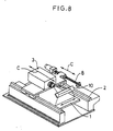
- A conventional inspection apparatus is shown in Figs. 7 to 10.
- As shown in Fig. 7 and 8, the inspection apparatus is configured such that an inspection is made by causing a
line sensor camera 3 to photograph a printedcircuit board 1 conveyed to an inspection position, by scanning that printedcircuit board 1 in a direction (direction indicated by arrow C) along the direction of board conveyance. - More specifically, the printed
circuit board 1 in the inspection position is held by a pair ofrails 2 being constant in breadth and constituting a pair of holding members. Theline sensor camera 3 is movable in the direction of arrow C by amovement shaft 8, and photographs the surface of the printedcircuit board 1 through a reflectingmirror 10. - In an inspection apparatus configured in this way, the
movement shaft 8 is sometimes caused to expand and contract or the printedcircuit board 1 to expand and contract due to factors such as heat. - For this reason, in the printed
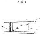
circuit board 1 being inspected, as shown in Fig. 9, afirst correction mark 6e and asecond correction mark 6f are provided on the side where theline sensor camera 3 starts reading and on the side where it ends reading, respectively, such that these correction marks 6e and 6f are positioned on a diagonal line passing through theboard 1. Using the correction marks in these two places, any discrepancy in themovement shaft 8 or printedcircuit board 1 described above is corrected. - In more specific terms, when the printed
circuit board 1 is photographed by theline sensor camera 3, thecorrection marks line sensor camera 3 and center positions therefor are found respectively. Coordinate positions for thecorrection marks line sensor camera 3 are defined as (xe, ye) and (xf, yf) respectively. - Here, coordinate positions for the first and
second correction marks first correction mark 6e and thesecond correction mark 6f in the X axis direction and the Y axis direction have been known, so that based on the distances and the recognition with the line sensor camera, the ratios of the distances between the first andsecond correction marks - When the ratios in the X axis direction and the Y axis direction are both valued 1, it can be judged that there is no expansion or contraction in the
movement shaft 8 or the printedcircuit board 1. When the ratio is other than 1, however, it is judged that there is expandsion or contraction in themovement shaft 8 and/or printedcircuit board 1, whereupon adjustments are made to respective coordinate positions in an image so that the recognized positions of the correction marks become the taught values, and the position of the printedcircuit board 1 is also adjusted. - More specifically, assuming that the expansion and contraction are uniform, respective X-coordinate and Y-coordinate values in the recognized image are divided by γx and γy to produce corrected values so that a corrected image can be presented.
- However, as will be explained below, there is a problem with the inspection method described in the foregoing in that it cannot be used when the printed
circuit board 1 is so large in the breadth direction of therails 2 that it cannot be thoroughly scanned by the line censor camera. - When the printed
circuit board 1 is too large as mentioned above, one possibility is to provide the printedcircuit board 1 with a screw shaft that is movable in the breadth direction of therails 2. By rotating the screw shaft, the printedcircuit board 1 is moved in the breadth direction of the rails 2a while photographs are taken with the line sensor camera 3 a plural number of times. - When the printed
circuit board 1 is photographed two times with theline sensor camera 3, for example, first, as shown in Fig. 10(a-1), theline sensor camera 3 is moved from a firstscan start position 5c in the direction indicated by arrow E1, whereupon afirst scan area 7a wherein afirst inspection point 11a is provided is photographed. - Next, as shown in Fig. 10(a-2), the printed
circuit board 1 is moved in the direction indicated by arrow E2 by the screw shaft, and asecond scan area 7b wherein asecond inspection point 11b is provided is photographed from a secondscan start position 5d. - The printed
circuit board 1, after photographing is concluded, is moved in the direction indicated by arrow F by the screw shaft, as shown in Fig. 10(a-3), and returned to the original position. - When there is contained a process step for moving the printed
circuit board 1 by a screw shaft in the breadth direction of therails 2, as described above, there is a problem in that when printedcircuit boards 1 are conveyed successively and each printed circuit board undergoes inspection, even if the position of the printedcircuit board 1 is altered by rotating the screw shaft for the same amount each time, the resulting amount of movement will not be constant in actual practice because of the influence of the thermal expansion of the screw shaft. - Figs. 10(b-1) to 10(b-3) show the inspection method for a case where there has been thermal expansion in the screw shaft.
- Fig. 10(b-1), where photographing is done in the same manner as shown in Fig. 10(a-1), shows a reference position for moving the printed
circuit board 1 with the screw shaft, so that the first scan startposition 5c and the firstscan start position 5e are at the same position, and there is no discrepancy between thefirst scan area 7a and thefirst scan area 7c photographed by theline sensor camera 3. - However, when thermal expansion occurs in the screw shaft, the moved printed
circuit board 1, as shown in Fig. 10(b-2), even though the screw shaft is rotated for the same amount as shown in Fig. 10(a-2), exhibits a discrepancy between the secondscan start position 5f and the secondscan start position 5d in the breadth direction of therails 2. - As a result, the distance from the second
scan start position 5d to thesecond correction mark 6f as shown in Fig. 10(a-2) differs from the distance from the secondscan start position 5f to thesecond correction mark 6h as shown in Fig. 10(b-2). Likewise, the distance from the secondscan start position 5d to thesecond inspection point 11b as shown in Fig. 10(a-2) differs from the distance from the secondscan start position 5f to thesecond inspection point 11d as shown in Fig. 10(b-2). Accordingly, overall dislocation has occurred between the image including thefirst scan area 7c and thesecond scan area 7d as shown in Fig. 10(b-3), and the image including the first scan area 7s and thesecond scan area 7b as shown in Fig. 10(a-3). - Thus, when a discrepancy in the rotational driving amount of the screw shaft occurs due to heat or the like, a discrepancy occurs in the scan start position, so that a contraction correction method that uses a
first correction mark 6c and asecond correction mark 6f, as described in the foregoing, cannot be employed. - An object of the present invention is to provide a high-precision inspection apparatus and inspection method capable of inspecting a large board by laterally moving the board and photographing the board for a plural number of times before and after the lateral moving.
- The inspection method of the present invention is characterized in that a to-be-inspected board is moved laterally and an amount of movement of holding members of the board is corrected based on an amount of positional discrepancy of the board.
- According to this aspect of the invention, large boards can be inspected, and high-precision inspections can be effected.
- The inspection apparatus of the invention is characterized in that correction marks are provided on the holding members for holding the board.
- According to this aspect of the invention, the inspection method of the present invention can be easily implemented.
- The inspection, method described in
claim 1 of the present invention is a method for inspecting a to-be-inspected board by photographing the board that has been conveyed to an inspection position, in which a pair of holding members constituted of a pair of rails for holding the board are moved to move the board in a direction crossing a scanning direction of a photography unit and the board that has been positioned is scanned by the photography unit along the direction of said conveyance of the board, the inspection method comprising: reading coordinate positions of correction marks applied to said holding members by said photography unity computing an amount of positional discrepancy of the board by comparing coordinate positions of correction marks previously set with the coordinate positions of correction marks having been read; and when there are discrepancies between said two kinds of coordinate positions, carrying out said photographing after correcting an amount of movement of the holding members based on said amount of positional discrepancy of the board. - The inspection method according to
claim 2 of the present invention is a method for inspecting a to-be-inspected board by photographing the board that has been conveyed to an inspection position, in which a pair of holding members constituted of a pair of rails located in an opposed relation to each other for holding the board are moved to move the board in a direction crossing a scanning direction of a photography unit and the board that has been positioned is scanned by the photography unit along the direction of said conveyance of the board, the inspection method comprising: reading a coordinate position of a first correction mark applied to one of the holding members by said photography unit; moving said holding members and reading a coordinate position at a second correction mark applied to the other of the holding members, said second correction mark on said the other of the holding members being on the side opposite to that of the first correction mark on said one of the holding members with the board being interposed therebetween; computing an amount of positional discrepancy of the board by comparing coordinate positions of first and second correction marks previously set with the coordinate positions of the first and second correction marks having been read; and when there are discrepancies between said two kinds of coordinate positions, carrying out said photographing after correcting an amount of movement of the holding members based on said amount of positional discrepancy of the board. - The inspection method described in
claim 3 of the present invention is a method for inspecting a to-be-inspected board by photographing the board that has been conveyed to an inspection position, in which a pair of holding members constituted of a pair of rails for holding the board are moved to move the board in a direction crossing a scanning direction of a photography unit and the board that has been positioned is scanned by the photography unit along the direction of said conveyance of the board, the inspection method comprising: reading coordinate positions of correction marks applied to said board by said photography unit; computing an amount of positional discrepancy of said board by comparing coordinate positions of correction marks previously set with the coordinate positions of the correction marks having been read; and when there are discrepancies between said two kinds of coordinate positions, carrying out said photographing after correcting an amount of movement of the holding members based on said amount of positional discrepancy of the board. - The inspection method described in
claim 4 of the present invention is a method according toclaim 2, wherein the first and second correction marks are provided on the side where the photography unit starts reading. - The inspection method described in
claim 5 of the present invention is a method according toclaim 3, wherein a first correction mark and a second correction mark are provided on the board, said first correction mark being provided on the side where the photography unit starts reading, said second correction mark being provided on a diagonal line passing said first correction mark. - The inspection apparatus described in
claim 6 of the present invention is an apparatus for inspecting a to-be-inspected board by photographing the board that has been conveyed to an inspection position, in which a pair of holding members constituted of a pair of rails for holding the board are moved to move the board in a direction crossing a scanning direction of a photography unit and the board that has been positioned is scanned by the photography unit along the direction of said conveyance of the board, the inspection apparatus comprising: a control unit configured to read coordinate positions of correction marks applied to the holding members by the photography unit, to compute an amount of positional discrepancy of the board by comparing coordinate positions of correction marks previously set with the coordinate positions of the correction marks having been read, and when there are discrepancies between said two kinds of coordinate positions, to carry out said photographing after correcting an amount of movement of the holding members based on said amount of positional discrepancy of the board. - The inspection apparatus described in
claim 7 of the present invention is an apparatus for inspecting a to-be-inspected board by photographing the board that has been conveyed to an inspection position, in which a pair of holding members constituted of a pair of rails for holding the board are moved to move the board in a direction crossing a scanning direction of a photography unit and the board that has been positioned is scanned by the photography unit along the direction of said conveyance of the board, the inspection apparatus comprising: a control unit configured to read coordinate positions of correction marks applied to said board by the photography unit, to compute an amount of positional discrepancy of the board by comparing coordinate positions of correction marks previously set with the coordinate positions of the correction marks having been read, and when there are discrepancies between said two kinds of coordinate positions, to carry out the photographing after correcting an amount of movement of the holding members based on said amount of positional discrepancy of the board. -
- Fig. 1 is a schematic plan view of an inspection apparatus in a first embodiment of the present invention;
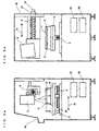
- Fig. 2 is a side elevation and front elevation of the inspection apparatus in the first embodiment of the present invention;
- Fig. 3 is a block diagram of the inspection apparatus in the first embodiment of the present invention;
- Fig. 4 is a flowchart showing an inspection method in the first embodiment of the present invention;
- Fig. 5 is a schematic plan view of an inspection apparatus in a second embodiment of the present invention;
- Fig. 6 is a flowchart showing an inspection method in the second embodiment of the present invention;
- Fig. 7 is a perspective view of a conventional inspection apparatus;
- Fig. 8 is a perspective view of a main part of the conventional inspection apparatus;
- Fig. 9 is a schematic plan view of the conventional inspection apparatus; and
- Fig. 10 is a schematic illustration showing steps in a conventional inspection method.
-
- Embodiment aspects are now described with the use of Fig. 1 to 5.
- In this description, the same or similar items as those indicated in Fig. 7 to 10 diagramming the conventional example, as noted earlier, are designated by the same symbols.
- First embodiment in the present invention is shown in Fig. 1 to 4.
- This first embodiment, as shown in Fig. 1, differs from the conventional example described earlier in that a screw shaft (ball screw shaft) 4 is provided for moving a printed
circuit board 1, that is a board being inspected, in a direction crossing the direction of conveyance of the board (the direction indicated by arrow C), for example, in the breadth direction of a pair ofrails 2 indicated by arrow B, and correction marks for correcting the amount of rotational drive of thescrew shaft 4 are provided on the side of therails 2. - More specifically, as shown in Fig. 2(a) and 2(b), the
inspection apparatus 40 is comprised of two movement shafts, namely thescrew shaft 4 for moving the printedcircuit board 1 which has been conveyed to an inspection position, along the breadth direction of the rails 2 (direction indicated by arrow B), and amovement shaft 8 for moving aline sensor camera 3 or a photography unit along the direction of conveyance of the board (direction indicated by arrow A.). - Here, 9 represents a moving platform for mounting thereon the pair of
rails 2, which is driven to move in the direction indicated by arrow B as thescrew shaft 4 rotates; 20 a motor for rotationally driving thescrew shaft 4; 21 a rotary encoder for detecting an amount of rotation of themotor 20; 22 a motor for rotationally driving themovement shaft 8; 23 a rotary encoder for detecting an amount of rotation of themotor 22; 25 a control unit for controlling the overall inspection apparatus including themotors line sensor camera 3. - The control system of the
inspection apparatus 40 is configured as shown in Fig. 3. - In Fig. 3, the
control unit 25 is connected with aninput device 26 andCRT 31, so that an operator operates theinspection apparatus 40 by inputting instructions, information data and so on to theinput device 26 while watching theCRT 31. Represented by 32 is a storage unit for storing therein data input from theinput device 26, control programs necessary to actuate theinspection apparatus 40, control parameters, image data photographed by theline sensor camera 3 and so on. - The
control unit 25 rotationally drives themotor 20 for moving the board, and the amount of rotation of themotor 20 is detected by theencoder 21. Likewise, thecontrol unit 25 rotationally drives themotor 22 for moving the line sensor camera, and the amount of rotation of themotor 22 is detected by theencoder 23. - The printed
circuit board 1 is held by the pair ofrails 2 constituting a pair of holding members, and first and second correction marks 6a and 6b for the holding members are provided on theside 51 of therails 2 where theline sensor camera 3 starts reading. - The
screw shaft 4 sometimes expands or contracts due to heat and other factors, with the passage of time, so that discrepancies can occur between coordinate positions where the first and second holding member correction marks 6a and 6b have been recognized on therails 2 at a point of time t1, and coordinate positions where the first and second holding member correction marks 6a and 6b have been recognized on therails 2 at another point of time t2 after a passage of a certain period of time from t1. - As a result, a positional discrepancy occurs at the first
scan start position 5a and the secondscan start position 5b, respectively, and a discrepancy occurs in the first andsecond inspection areas - Thereupon, in this first embodiment, the coordinate positions of the first and second holding member correction marks 6a and 6b are read by the
line sensor camera 3, and the control illustrated by the flow chart shown in Fig. 4 is performed by thecontrol unit 25 so that the amount of movement of the printedcircuit board 1 in the direction indicated by arrow B is corrected. - First, in step S1, the coordinate positions of the first and second correction marks 6a and 6b are set by the
input device 26 and stored in thestorage unit 32. - In step S2, the
motor 20 is driven to move the printedcircuit board 1 in the direction of B in order to photograph the first scan area of the printedcircuit board 1. - In step S3, every time one printed
circuit board 1 is inspected, or once every several boards have been inspected, or when a value measured by a screwshaft temperature detector 35 for detecting temperature of thescrew shaft 4 exceeds a previously set threshold value, thefirst correction mark 6a provided on one of therails 2 constituting the holding members is recognized, and in step S4, according to the instruction from thecontrol unit 25, theline sensor camera 3 is moved in the direction A to photograph the first holdingmember correction mark 6a, and thus photographed correction mark is subjected to image processing by theimage processing unit 30 so that the position of the first holdingmember correction mark 6a is detected. Then, the amount of positional discrepancy between the coordinate position of the first holdingmember correction mark 6a detected by photography and that of the set holdingmember correction mark 6a is computed. - When it is judged in step S5 that there is a discrepancy between the coordinate positions of the two kinds of the
first correction marks 6a, the amount of movement of the printedcircuit board 1 is corrected and the positional discrepancy of the firstscan start position 5a is corrected in step S6. - Specifically, the amount of rotation of the
motor 22 is detected by theencoder 23 in order that themotor 22 rotates for the same amount corresponding to the amount of positional discrepancy obtained in step S4, thereby correcting the amount of positional discrepancy and solving the problem associated with such discrepancy. - After the corrections the amount of coordinate positional discrepancy of the first holding member correction mark is detected again in steps S3 and S4, and in step S5, it is determined whether or not there exists the positional discrepancy. This is repeated until it is determined in step S5 that there exists no more positional discrepancy.
- When it is judged in step S5 that there is no positional discrepancy, in step S7, the
line sensor camera 3 is moved, for example, from a readingstart side 51 toward a readingend side 52 as shown in Fig. 1, in order to photograph thefirst scan area 7a of the printedcircuit board 1 by theline sensor camera 3. - At the same time, the
first correction mark 6c provided on the printedcircuit board 1 is photographed, and its center position is obtained by image processing by theimage processing unit 30. - When it is judged in step S5 that there is no positional discrepancy, too, the printed
circuit board 1 is photographed in step S7. - Next, in step S8, according to the instruction from the
control unit 25, themotor 20 is rotationally driven for an amount of movement corresponding to the distance from the previously set first holdingmember correction mark 6a to the second holdingmember correction mark 6b, and the printedcircuit board 1 is moved in the direction B to a position where the second scan area is photographed. - In step S9, according to the instruction, from the
control unit 25, theline sensor camera 3 is moved in the direction A, and the second holdingmember correction mark 6b is photographed. And in step S10, the amount of positional discrepancy between the coordinate position of the second holdingmember correction mark 6b which has been read and the coordinate position of the previously set second holdingmember correction mark 6b is computed. - When it is judged in step S11 that there is a coordinate positional discrepancy with the second holding
member correction mark 6b, in the same manner as in step S6, the amount of movement of the printedcircuit board 1 is corrected and the positional discrepancy of the firstscan start position 5a is corrected. Such corrections are repeated in steps S9 and S10, until it is judged again that there is no positional discrepancy in step S11. - When it is judged that there is no positional discrepancy in step S11, the
second scan area 7b of the printedcircuit board 1 is photographed by theline sensor camera 3 in step S13. At the same time, theboard correction mark 6d on the printedcircuit board 1 is also photographed, and its center position is obtained through image processing by theimage processing unit 30. - Next, in step S14, the amount of discrepancies between the recognized coordinate positions of the first and second board correction marks 6c and 6d obtained in step S7 and step S13, and the coordinate positions of the board correction marks 6c and 6d previously set is computed, and in order to solve the discrepancy amount, the image of the printed circuit board including the first scan area and the second scan area combined is corrected by employing the conventional method earlier mentioned so that the board correction marks 6c and 6d appearing on the image correspond to the previously set positions.
- In step S15, the corrected image of the printed circuit board is subjected to image processing and inspection judgment, thereafter the result of inspection is output.
- By performing such correction as described above, positional corrections can be performed to compensate for the expansion and contraction in movement shafts and in printed circuit boards caused by heat and other factors, even in inspection machines that are configured with biaxial movement shafts.
- In the foregoing description, the first and second correction marks 6a and 6b are placed in an opposed relations to each other on the rails on the side where the
line sensor camera 3 starts reading, but the present invention is not limited thereto or thereby, and their set positions can be adjusted as may be expedient. - Second embodiment of the present invention is shown in Figs. 5 and 6.
- In this embodiment, although there is a difference from the first embodiment described in the foregoing in that correction marks are provided on a printed
circuit board 1, in other respects the basic configuration is the same as in the first embodiment. - Specifically, as shown in Fig. 5, a first
board correction mark 6c is provided on a printedcircuit board 1 on the side where aline sensor camera 3 starts reading the printedcircuit board 1 as shown in Fig. 9 which shows a conventional example, and a secondboard correction mark 6d is provided on a diagonal line passing thefirst correction mark 6c. - The printed
circuit board 1 conveyed to the inspection position is moved by ascrew shaft 4 in the direction indicated by arrow B, and theline sensor camera 3 is moved in the direction indicated by arrow A, whereby afirst scan area 7a and asecond scan area 7b are subjected to inspection. - In an inspection apparatus configured in this way, when expansion or contraction occurs in the
screw shaft 4 over the course of time due to heat and/or other factors, and a discrepancy occurs between the position obtained as a result of recognition of the board correction marks 6c and 6d on the printedcircuit board 1 at some point of time and the position obtained as a result of recognition of the board correction marks 6c and 6d on the printedcircuit board 1 after a passage of some period of time, the position of the printedcircuit board 1 is corrected by the control unit shown in Fig. 6. - First, in step S1, the coordinate positions of the first and second board correction marks 6c and 6d are set by the
input device 26 and stored in thestorage unit 32. - In step S2, the
motor 20 is driven to move the printedcircuit board 1 in the direction of B in order to photograph the first scan area of the printedcircuit board 1. - In step S3, every time one printed
circuit board 1 is inspected, or once every several boards have been inspected, or when a value measured by a screwshaft temperature detector 35 for detecting temperature of thescrew shaft 4 exceeds a previously set threshold value, the firstboard correction mark 6c provided on the printed circuit board is recognized, and in step S4, according to the instruction from thecontrol unit 25, theline sensor camera 3 is moved in the direction A to photograph the firstboard correction mark 6c, and thus photographed correction mark is subjected to image processing by theimage processing unit 30 so that the position of the firstboard correction mark 6c is detected. Then, the amount of positional discrepancy between the coordinate position of the firstboard correction mark 6c detected by photography and that of the setboard correction mark 6c is computed. - When it is judged in step S5 that there is a discrepancy between the coordinate positions of the two kinds of the first board correction marks 6c, the amount of movement of the printed
circuit board 1 is corrected and the positional discrepancy of the firstscan start position 5a is corrected in step S6. - Specifically, the amount of rotation of the
motor 22 is detected by theencoder 23 in order that themotor 22 rotates for the same amount corresponding to the amount of positional discrepancy obtained in step S4, thereby correcting the amount of positional discrepancy and solving the problem associated with such discrepancy. - After the correction, the amount of coordinate positional discrepancy of the first board correction mark is detected again in steps S3 and S4, and in step S5, it is determined whether or not there exists the positional discrepancy. This is repeated until it is determined in step S5 that there exists no more positional discrepancy.
- When it is judged in step S5 that there is no positional discrepancy, in step S7, the
line sensor camera 3 is moved, for example, from a readingstart side 51 toward a readingend side 52 as shown in Fig. 5, in order to photograph thefirst scan area 7a of the printedcircuit board 1 by theline sensor camera 3. - At the same time, the first
board correction mark 6c provided on the printedcircuit board 1 is photographed, and its center position is obtained by image processing by theimage processing unit 30. - When it is judged in step S5 that there is no positional discrepancy, too, the printed
circuit board 1 is photographed in step S7. - Next, in step S8, according to the instruction from the
control unit 25, themotor 20 is rotationally driven for an amount of movement in the direction B corresponding to the distance from the previously set firstboard correction mark 6c to the secondboard correction mark 6d, and the printedcircuit board 1 is moved in the direction B to a position where the second scan area is photographed. - In step S9, according to the instruction from the
control unit 25, theline sensor camera 3 is moved in the direction A, and the secondboard correction mark 6d is photographed. And in step S10, the amount of positional discrepancy between the coordinate position of the secondboard correction mark 6d which has been read and the coordinate position of the previously set secondboard correction mark 6d is computed. - When it is judged in step S11 that there is a coordinate positional discrepancy with the second
board correction mark 6d, in the same manner as in step S6, the amount of movement of the printedcircuit board 1 is corrected and the positional discrepancy of the firstscan start position 5a is corrected. Such corrections are repeated in steps S9 and S10, until it is judged again that there is no positional discrepancy in step S11. - When it is judged that there is no positional discrepancy in step S11, the
second scan area 7b of the printedcircuit board 1 is photographed by theline sensor camera 3 in step S13. At the same time, theboard correction mark 6d on the printedcircuit board 1 is also photographed, and its center position is obtained through image processing by theimage processing unit 30. - Next, in step S14, the amount of discrepancies between the recognized coordinate positions of the first and second board correction marks 6c and 6d obtained in step S7 and step S13, and the coordinate positions of the board correction marks 6c and 6d previously set is computed, and in order to solve the discrepancy amount, the image of the printed circuit board including the first scan area and the second scan area combined is corrected by employing the conventional method earlier mentioned so that the board correction marks 6c and 6d appearing on the image correspond to the previously set positions.
- In step S15, the corrected image of the printed circuit board is subjected to image processing and inspection judgment, thereafter the result of inspection is output.
- By performing such correction as described above, positional corrections can be performed to compensate for the expansion and contraction in movement shafts and in printed circuit boards due to heat and/or other factors, even in inspection machines that are configured with two movement shafts as in the first embodiment described earlier.
- In the foregoing description, the positional discrepancy of the screw shaft is corrected using the same first and second correction marks as used in the conventional expansion and contraction correction method, but the present invention is not limited thereto or thereby, nor is there any particular limitation on the positions of the first and second board correction marks used in the correction shown in Fig. 5
- In the embodiments mentioned above, description has been made by citing a ball screw as an element constituting the movement shaft, but the present invention is not limited thereto or thereby, and can be embodied with some other drive means such as a timing belt or the like.
- As is clear from the embodiments mentioned above, according to the inspection method of the present invention, the coordinate positions or correction marks applied to holding members are read by a line sensor camera, an amount of positional discrepancy of a board is computed by comparing previously set coordinate positions of the correction marks with coordinate positions of the read correction marks, and when there are discrepancies between the two kinds of coordinate positions, photographing noted earlier is performed after correcting an amount of movement of the holding members based on the amount of positional discrepancy of the board, whereby it is possible to inspect a large-size board by laterally moving the board and photographing the same for a plural number of times before and after the lateral moving, and it is also possible to achieve high-precision inspection.
- Further, with the inspection apparatus of the present invention, the inspection method of the present invention can be easily implemented by providing a control unit configured so that the coordinate positions of the correction marks applied to the holding members are read by the line sensor camera, an amount of positional discrepancy of the board is computed by comparing the coordinate positions of the previously set correction marks with the coordinate positions of the read correction marks, and when there are coordinate-positional discrepancies between the two kind of correction marks, the photographing is performed after correcting the amount of movement of the holding members based on the amount of positional discrepancy of the board.
Claims (7)
- An inspection method for inspecting a to-be-inspected board (1) by photographing the board (1) that has been conveyed to an inspection position, in which a pair of holding members (2) for holding the board (1) are moved to move the board (1) in a direction crossing a scanning direction of a photography unit (3) and the board that has been positioned is scanned by the photography unit (3) along the direction of said conveyance of the board (1), the inspection method comprising:reading coordinate positions of holding member correction marks (6a and 6b) applied to said holding members (2) by said photography unit (3);computing an amount of positional discrepancy of the board by comparing coordinate positions of holding member correction marks (6a and 6b) previously set with the coordinate positions of holding member correction marks (6a and 6b) having been read; andwhen there are discrepancies between said two kinds of coordinate positions, carrying out said photographing after correcting an amount of movement of the holding members based on said amount of positional discrepancy of the board.
- An inspection method for inspecting a to-be-inspected board (1) by photographing the board (1) that has been conveyed to an inspection position, in which a pair of holding members (2) constituted of a pair of rails located in an opposed relation to each other for holding the board (1) are moved to move the board (1) in a direction crossing a scanning direction of a photography unit (3) and the board that has been positioned is scanned by the photography unit (3) along the direction of said conveyance of the board (1), the inspection method comprising:reading a coordinate position of a first holding member correction mark (6a) applied to one of the holding members (2) by said photography unit (3);moving said holding members (2) and reading a coordinate position of a second holding member correction mark (6b) applied to the other of the holding members (2), said second holding member correction mark (6b) on said the other of the holding members being on the side opposite to that of said first holding member correction mark (6a) on said one of the holding members with the board (1) being interposed therebetween;computing an amount of positional discrepancy of the board by comparing coordinate positions of first and second holding member correction marks (6a and 6b) previously set with the coordinate positions of the first and second holding member correction marks (6a and 6b) having been read; andwhen there are discrepancies between said two kinds of coordinate positions, carrying out said photographing after correcting an amount of movement of the holding members based on said amount of positional discrepancy or the board.
- An inspection method for inspecting a to-be-inspected board (1) by photographing the board (1) that has been conveyed to an inspection position, in which a pair of holding members (2) for holding the board (1) are moved to move the board (1) in a direction crossing a scanning direction of a photography unit (3) and the board that has been positioned is scanned by the photography unit (3) along the direction of said conveyance of the board (1), the inspection method comprisingreading coordinate positions of board correction marks (6c and 6d) applied to said board (1) by said photography unit (3);computing an amount of positional discrepancy of said board by comparing coordinate positions of board correction marks (6c and 6d) previously set with the coordinate positions of the board correction marks (6c and 6d) having been read; andwhen there are discrepancies between said two kinds of coordinate positions, carrying out said photographing after correcting an amount of movement of the holding members based on said amount of positional discrepancy of the board.
- The inspection method according to claim 2, wherein the first and second holding member correction marks (6a and 6b) are provided on the side where the photography unit (3) starts reading.
- The inspection method according to claim 3, wherein a first board correction mark (6c) and a second board correction mark (6d) are provided on the board (1), said first board correction mark (6c) being provided on the side where the photography unit (3) starts reading, said second board correction mark (6d) being provided on a diagonal line passing said first board correction mark (6c).
- An inspection apparatus for inspecting a to-be-inspected board (1) by photographing the board (1) that has been conveyed to an inspection position, in which a pair of holding members (2) for holding the board (1) are moved to move the board (1) in a direction crossing a scanning direction of a photography unit (3) and the board that has been positioned is scanned by the photography unit (3) along the direction of said conveyance of the board (1), the inspection apparatus comprising:a control unit configured to read coordinate positions of holding member correction marks (6a and 6b) applied to the holding members (2) by the photography unit (3), to compute an amount of positional discrepancy of the board (1) by comparing coordinate positions of holding member correction marks (6a and 6b) previously set with the coordinate positions of the holding member correction marks (6a and 6b) having been read, and when there are discrepancies between said two kinds of coordinate positions, to carry out said photographing after correcting an amount of movement of the holding members (2) based on said amount of positional discrepancy of the board.
- An inspection apparatus for inspecting a to-be-inspected board (1) by photographing the board (1) that has been conveyed to an inspection position, in which a pair of holding members (2) constituted of a pair of rails for holding the board (1) are moved to move the board (1) in a direction crossing a scanning direction of a photography unit (3) and the board that has been positioned is scanned by the photography unit (3) along the direction of said conveyance of the board (1), the inspection apparatus comprising:a control unit configured to read coordinate positions of board correction marks (6c and 6d) applied to said board (1) by the photography unit (3), to compute an amount of positional discrepancy of the board (1) by comparing coordinate positions of board correction marks (6c and 6d) previously set with the coordinate positions of the board correction marks (6c and 6d) having been read, and when there are discrepancies between said two kinds of coordinate positions, to carry out the photographing after correcting an amount of movement of the holding members (2) based on said amount of positional discrepancy of the board.
Applications Claiming Priority (2)
| Application Number | Priority Date | Filing Date | Title |
|---|---|---|---|
| JP30321099 | 1999-10-26 | ||
| JP30321099A JP2001127499A (en) | 1999-10-26 | 1999-10-26 | Inspection method and inspection device |
Publications (1)
| Publication Number | Publication Date |
|---|---|
| EP1096846A1 true EP1096846A1 (en) | 2001-05-02 |
Family
ID=17918213
Family Applications (1)
| Application Number | Title | Priority Date | Filing Date |
|---|---|---|---|
| EP00123253A Withdrawn EP1096846A1 (en) | 1999-10-26 | 2000-10-26 | Inspection method and inspection apparatus for printed circuit boards |
Country Status (3)
| Country | Link |
|---|---|
| US (2) | US6512363B1 (en) |
| EP (1) | EP1096846A1 (en) |
| JP (1) | JP2001127499A (en) |
Families Citing this family (6)
| Publication number | Priority date | Publication date | Assignee | Title |
|---|---|---|---|---|
| TWI221727B (en) * | 2003-07-07 | 2004-10-01 | Avision Inc | Method for adjusting a scanning module |
| US7528617B2 (en) * | 2006-03-07 | 2009-05-05 | Testmetrix, Inc. | Apparatus having a member to receive a tray(s) that holds semiconductor devices for testing |
| US7869645B2 (en) * | 2008-07-22 | 2011-01-11 | Seiko Epson Corporation | Image capture and calibratiion |
| US8090184B2 (en) * | 2008-07-23 | 2012-01-03 | Seiko Epson Corporation | Fault detection of a printed dot-pattern bitmap |
| US8269836B2 (en) * | 2008-07-24 | 2012-09-18 | Seiko Epson Corporation | Image capture, alignment, and registration |
| CN109374650B (en) * | 2018-08-27 | 2021-08-24 | 常熟东南相互电子有限公司 | Device and method for detecting double-sided CCD of circuit board |
Citations (5)
| Publication number | Priority date | Publication date | Assignee | Title |
|---|---|---|---|---|
| US4668982A (en) * | 1985-06-17 | 1987-05-26 | The Perkin-Elmer Corporation | Misregistration/distortion correction scheme |
| US4783826A (en) * | 1986-08-18 | 1988-11-08 | The Gerber Scientific Company, Inc. | Pattern inspection system |
| JPH06252596A (en) * | 1993-02-26 | 1994-09-09 | Pioneer Electron Corp | Electronic component mounting device for |
| GB2327302A (en) * | 1997-07-14 | 1999-01-20 | Motorola Inc | Judging circuit board assembly by inspecting an isolated representative "test" assembly on the board |
| WO1999041621A2 (en) * | 1998-02-13 | 1999-08-19 | Scientific Generics Limited | Circuit board assembly inspection |
Family Cites Families (5)
| Publication number | Priority date | Publication date | Assignee | Title |
|---|---|---|---|---|
| GB8700754D0 (en) * | 1987-01-14 | 1987-02-18 | Int Computers Ltd | Test apparatus for printed circuit boards |
| US5408189A (en) * | 1990-05-25 | 1995-04-18 | Everett Charles Technologies, Inc. | Test fixture alignment system for printed circuit boards |
| US5321352A (en) * | 1991-08-01 | 1994-06-14 | Tokyo Electron Yamanashi Limited | Probe apparatus and method of alignment for the same |
| FR2692048B1 (en) * | 1992-06-09 | 1996-09-06 | Everett Charles Tech | TEST ASSEMBLY. |
| JP4014270B2 (en) * | 1998-01-06 | 2007-11-28 | 富士機械製造株式会社 | Substrate support pin arrangement method, arrangement inspection method and apparatus |
-
1999
- 1999-10-26 JP JP30321099A patent/JP2001127499A/en active Pending
-
2000
- 2000-10-26 US US09/696,176 patent/US6512363B1/en not_active Expired - Fee Related
- 2000-10-26 EP EP00123253A patent/EP1096846A1/en not_active Withdrawn
-
2002
- 2002-12-06 US US10/310,779 patent/US6707289B2/en not_active Expired - Fee Related
Patent Citations (5)
| Publication number | Priority date | Publication date | Assignee | Title |
|---|---|---|---|---|
| US4668982A (en) * | 1985-06-17 | 1987-05-26 | The Perkin-Elmer Corporation | Misregistration/distortion correction scheme |
| US4783826A (en) * | 1986-08-18 | 1988-11-08 | The Gerber Scientific Company, Inc. | Pattern inspection system |
| JPH06252596A (en) * | 1993-02-26 | 1994-09-09 | Pioneer Electron Corp | Electronic component mounting device for |
| GB2327302A (en) * | 1997-07-14 | 1999-01-20 | Motorola Inc | Judging circuit board assembly by inspecting an isolated representative "test" assembly on the board |
| WO1999041621A2 (en) * | 1998-02-13 | 1999-08-19 | Scientific Generics Limited | Circuit board assembly inspection |
Non-Patent Citations (1)
| Title |
|---|
| PATENT ABSTRACTS OF JAPAN vol. 018, no. 646 (E - 1641) 8 December 1994 (1994-12-08) * |
Also Published As
| Publication number | Publication date |
|---|---|
| JP2001127499A (en) | 2001-05-11 |
| US20030080727A1 (en) | 2003-05-01 |
| US6512363B1 (en) | 2003-01-28 |
| US6707289B2 (en) | 2004-03-16 |
Similar Documents
| Publication | Publication Date | Title |
|---|---|---|
| EP0563829B1 (en) | Device for inspecting printed cream solder | |
| CN103079746A (en) | Laser processing apparatus and substrate position detecting method | |
| US6760054B1 (en) | Imaging apparatus utilizing laser beams | |
| US6512363B1 (en) | Method and apparatus for automatic registration of a board | |
| CN101765361B (en) | Method and apparatus for mounting electronic components | |
| JP4405009B2 (en) | Calibration method of inspection machine with line sensor camera | |
| JP6456726B2 (en) | Inspection device, inspection method, and inspection program | |
| KR0180269B1 (en) | Appearance inspection device and inspection method of tape carrier package | |
| JP3651718B2 (en) | Screen printing apparatus and printing method | |
| TWI800038B (en) | Measuring device and substrate inspection device | |
| JP3725993B2 (en) | Electronic component mounting circuit board inspection method and apparatus | |
| JP2561193B2 (en) | Print pattern inspection device | |
| JP2004325338A (en) | Device and method for inspecting printed circuit board | |
| JP2019039823A (en) | Inspection instrument | |
| JPH08330219A (en) | Scanning exposure device | |
| KR100819803B1 (en) | Solder Paste Inspection Method | |
| JP2847351B2 (en) | Automatic printed wiring board inspection system | |
| JP4419504B2 (en) | Image correction apparatus and image correction method | |
| JPH07302754A (en) | Scanning exposure device | |
| TWI901967B (en) | Template generating apparatus, drawing system, template generating method and computer readable program | |
| JPH01194322A (en) | Semiconductor printer | |
| KR20140016616A (en) | Device and method for correcting line scan camera | |
| JPH06294616A (en) | Edge position correcting method | |
| JPH05265027A (en) | Positioning method and device | |
| JPH0835817A (en) | Positional deviation detection apparatus and method for image |
Legal Events
| Date | Code | Title | Description |
|---|---|---|---|
| PUAI | Public reference made under article 153(3) epc to a published international application that has entered the european phase |
Free format text: ORIGINAL CODE: 0009012 |
|
| AK | Designated contracting states |
Kind code of ref document: A1 Designated state(s): DE GB |
|
| AX | Request for extension of the european patent |
Free format text: AL;LT;LV;MK;RO;SI |
|
| 17P | Request for examination filed |
Effective date: 20010606 |
|
| AKX | Designation fees paid |
Free format text: DE GB |
|
| 17Q | First examination report despatched |
Effective date: 20080409 |
|
| RAP1 | Party data changed (applicant data changed or rights of an application transferred) |
Owner name: PANASONIC CORPORATION |
|
| STAA | Information on the status of an ep patent application or granted ep patent |
Free format text: STATUS: THE APPLICATION IS DEEMED TO BE WITHDRAWN |
|
| 18D | Application deemed to be withdrawn |
Effective date: 20110503 |