EP1096469A2 - Ultrasonic vibration apparatus - Google Patents
Ultrasonic vibration apparatus Download PDFInfo
- Publication number
- EP1096469A2 EP1096469A2 EP00123558A EP00123558A EP1096469A2 EP 1096469 A2 EP1096469 A2 EP 1096469A2 EP 00123558 A EP00123558 A EP 00123558A EP 00123558 A EP00123558 A EP 00123558A EP 1096469 A2 EP1096469 A2 EP 1096469A2
- Authority
- EP
- European Patent Office
- Prior art keywords
- vibration
- casing
- ultrasonic
- disk
- vibration plate
- Prior art date
- Legal status (The legal status is an assumption and is not a legal conclusion. Google has not performed a legal analysis and makes no representation as to the accuracy of the status listed.)
- Granted
Links
Images






Classifications
-
- G—PHYSICS
- G10—MUSICAL INSTRUMENTS; ACOUSTICS
- G10K—SOUND-PRODUCING DEVICES; METHODS OR DEVICES FOR PROTECTING AGAINST, OR FOR DAMPING, NOISE OR OTHER ACOUSTIC WAVES IN GENERAL; ACOUSTICS NOT OTHERWISE PROVIDED FOR
- G10K9/00—Devices in which sound is produced by vibrating a diaphragm or analogous element, e.g. fog horns, vehicle hooters or buzzers
- G10K9/12—Devices in which sound is produced by vibrating a diaphragm or analogous element, e.g. fog horns, vehicle hooters or buzzers electrically operated
- G10K9/122—Devices in which sound is produced by vibrating a diaphragm or analogous element, e.g. fog horns, vehicle hooters or buzzers electrically operated using piezoelectric driving means
Definitions
- the present invention relates to an ultrasonic vibration apparatus such as an ultrasonic sensor used for detecting an object by transmitting and receiving ultrasonic waves.
- ultrasonic vibration apparatuses such as ultrasonic sensors employ a construction in which a piezoelectric element having an electrode formed on a piezoelectric plate is mounted in a casing.
- Fig. 9A is a cross sectional view showing a state in which a piezoelectric element 1 is mounted inside a casing 2.
- the casing 2 forms a cylindrical shape in which one end thereof serves as a disk-like vibration plate 2' and in which the piezoelectric element 1 is bonded on the inner face of the end.
- driving voltage is applied to the piezoelectric element 1
- the piezoelectric element 1 conducts a bending vibration at a predetermined resonance frequency.
- the disk-like vibration plate 2' also conducts the bending vibration.
- the resonance frequency depends on the material of the casing 2, the thickness a of the vibration plate 2', and the diameter b thereof.
- the sizes of the vibration plate 2' influence not only the resonance frequency of but also the directivities of the ultrasonic waves at transmission time and at reception time.
- directivity becomes narrowed.
- the outer diameter b of the casing is set to be large, further the thickness a is set to be great in order to set the resonance frequency to be high.
- the apparatus when the apparatus is used as an ultrasonic sensor, because of restriction in the size in the outer diameter and restriction of the wavelength to be used, the narrow directivity cannot be obtained without causing the apparatus to be large or without causing the operating frequency to be high.
- the relationship that the directivity is determined by the area of the above-described vibration face and the wavelength is applied to, strictly speaking, a case in which the vibrating face is parallel-vibrating in a piston-movement manner and in which the ultrasonic wave is emitted as a plane wave.
- the vibration plate 2' performs the bending vibration as shown in Fig. 9B, the ultrasonic waves propagate through air as a spherical wave front. Therefore, there is a problem in that little advantage in obtaining a narrow directivity is achieved even though the vibrating area is widened or the wavelength of the ultrasonic waves is shortened.
- Fig. 10 shows the result of computation by a finite-element method (FEM) which is applied to the appearance of deformation in a vibration plate (the casing) due to vibration in a conventional ultrasonic vibration apparatus as shown in Figs 9A and 9B.
- Fig. 11 shows the result obtained by computing directivity characteristics of the ultrasonic waves which are emitted by this deformation.
- FEM finite-element method
- Fig. 11 shows the result obtained by computing directivity characteristics of the ultrasonic waves which are emitted by this deformation.
- an angle (directivity angle) required to cause the sound pressure to be decreased up to -6.0 [dB], that is, to cause the sound pressure to be halved is as wide as 44 degrees.
- objects of this invention are to provide a miniaturized ultrasonic vibration apparatus showing narrow directivity characteristics without causing the frequency to be increased.
- an ultrasonic vibration apparatus which includes a casing having a vibration surface, a piezoelectric element mounted in the casing, and, a disk-like vibration plate supported at a position along a circle defining two regions, an inner region thereof and an outer region thereof.
- the disk-like vibration plate is constructed so as to be a part of the casing serving as the vibration face, and the piezoelectric element is mounted in the central part of the disk-like vibration plate, thereby causing the inner region and the outer region to vibrate in substantially the same phase.
- the casing may be constructed having a cylindrical shape with at least one end thereof closed and a groove is provided in an outer surface in proximity to the closed end of the casing thereby constituting the disk-like vibration plate.
- a flexible filler whose hardness is lower than that of the casing may be filled in the groove.
- the ultrasonic vibration apparatus may be used for an ultrasonic sensor.
- Figs. 1A, 1B, and 1C are cross sectional and top plan views showing the construction of the ultrasonic vibration apparatus.
- a casing 2 forms a cylindrical shape having one end thereof closed and is molded by die casting or cutting of aluminum.
- the closed end of this casing 2 is formed in which, by providing a groove 3 in the outer surface of the casing which is in proximity to the closed end, the thickness in the emitting direction of the outer peripheral surface of the casing which is in proximity to the closed end is reduced, thereby this closed overall end constitutes the disk-like vibration plate 2'.
- the above part having the thickness thereof reduced constitutes a supporting unit 4 for supporting the disk-like vibration plate 2'.
- the disk-like vibration plate 2' is divided into an inner region which is inside the supporting unit and an outer region which is outside the supporting unit.
- the disk-like piezoelectric element 1 is bonded in the central part of this disk-like vibration plate 2'.
- This piezoelectric element 1 is obtained by providing electrodes on both principal surfaces of the disk-like piezoelectric plate. By applying alternating voltage across the both electrodes, the piezoelectric element 1 conducts bending vibration.
- Fig. 1B shows a state in which the disk-like vibration plate 2' is deformed when vibrating due to piezoelectric vibration of the piezoelectric element 1.
- the disk-like vibration plate 2' also conducts bending vibration in which the supporting unit 4 serves as a node of vibration and in which the central part of the inner region and the outer peripheral portion of the outer region serve as antinodes.
- the diameter of the piezoelectric element 1 is 7.0 mm and the thickness thereof is 0.15 mm.
- resonance occurs at 80 kHz, and the inner region of the disk-like vibration plate 2' and the outer region thereof resonate in the same phase.
- Fig. 2 shows the appearance of interference among sound waves occurring due to vibration of the inner region and the outer region of the above vibration plate with respect to a plane passing through a center axis perpendicular to the vibration plate.
- Wa represents the density distribution of the sound waves due to vibration in the inner region of the vibration plate for each moment
- Wb represents the density distribution of the sound waves due to vibration in the outer region thereof for each moment.
- the sound pressure is minimized having such a direction that a condensed region thereof and a rarified region thereof overlap.
- This interference state is determined by the interval between the central part which is the antinode of vibration in the inner region of the vibration plate, and the outer peripheral portion which is the antinode of vibration in the outer region thereof; the wavelength of the generated ultrasonic waves; and the sound pressure of the ultrasonic waves generated in each part of the inner region and the outer region thereof. Therefore conditions are determined, as shown in this Fig.
- Fig. 3 shows the result of computation using a finite-element method (FEM) which is applied to the appearance of deformation of the vibration plate due to vibration of the ultrasonic vibration apparatus shown in Figs. 1A to 1C.
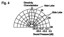
- Fig. 4 shows the result determined by computing directivity characteristics of the ultrasonic waves emitted due to the deformation.
- FEM finite-element method
- Fig. 4 shows the result determined by computing directivity characteristics of the ultrasonic waves emitted due to the deformation.
- an angle required for decreasing the sound pressure up to -6.0 [dB] that is, an angle (directivity angle) required for having the sound pressure halved is 24 degrees, which is approximately half of 44 degrees shown as the conventional example in Fig. 11.
- regions for intensifying the sound pressures to each other are generated in directions which are widely separated laterally from the front. They appear as relatively large side lobes. However, the extent of the interference is slight and the sound pressure is approximately -15.0 dB. Accordingly, they are substantially smaller than the main lobe at the front, which is insignificant.
- Figs. 5A to 5C are cross sectional and top plan views showing the construction of the ultrasonic vibration apparatus. It differs from the ultrasonic vibration apparatus shown in Figs. 1A to 1C in that filler 5 is filled in the groove 3. As this filler 5, flexible filling material having a hardness lower than that of the casing 2 is used.
- Fig. 5B shows a state in which the disk-like vibration plate 2' is deformed when vibrating due to piezoelectric vibration of the piezoelectric element 1.
- the disk-like vibration plate 2' bending-vibrates in which the supporting unit 4 thereof serves as a node of vibration and in which the central part of the inner region and the outer peripheral portion of the outer region serve as antinodes of vibration.
- the filler 5 causes vibration in the outer region to be damped. Therefore, after the burst signal for driving this ultrasonic vibration apparatus is finished, vibration in the outer region is rapidly damped. As a result, reverberation characteristics are effectively improved.
- Fig. 6A shows characteristics in a case in which bonding silicone rubber having a hardness of 50 and an elongation of 130% according to JISA, which is the Japanese Industrial Standard for rubber resin, is filled in the groove 3.
- Fig. 6B shows characteristics in a case in which such filler is not filled therein.
- t 8.0 ms
- duration of reverberation 700 ⁇ s
- Fig. 8 shows directivity characteristics of the above two ultrasonic vibration apparatuses.
- the tendency of the sound pressure to drop in which the sound pressure is varied in accordance with deviation of the directivity angle from 0 degree becomes gradual due to filling of the above filler. Therefore, the angle (directivity angle) required for having the sound pressure halved is wider. However, in this example, the widened angle is small.
- Fig. 7 is a diagram showing reverberation characteristics in which flexible filling material having a hardness of 20 and an elongation of 300 is filled in the groove 3.
- the reverberation time t becomes as long as 1340 ⁇ s in this example. Instead, the narrow directivity effect due to vibration in the above outer region is enhanced and the directivity angle is improved compared to a case shown in Fig. 8.
- both reverberation characteristics and directivity characteristics can be determined to optimal values within a predetermined specified range.
Landscapes
- Physics & Mathematics (AREA)
- Engineering & Computer Science (AREA)
- Acoustics & Sound (AREA)
- Multimedia (AREA)
- Transducers For Ultrasonic Waves (AREA)
- Apparatuses For Generation Of Mechanical Vibrations (AREA)
- Measurement Of Velocity Or Position Using Acoustic Or Ultrasonic Waves (AREA)
Abstract
Description
Claims (4)
- An ultrasonic vibration apparatus comprising:a casing (2) having a vibration surface;a piezoelectric element (1) mounted in said casing (2); anda disk-like vibration plate (2') supported at a position along a circle defining two regions, an inner region thereof and an outer region thereof,
wherein said disk-like vibration plate (2') is constructed so as to be a part of said casing (2) serving as said vibration surface; andsaid piezoelectric element (1) is provided in the central part of said disk-like vibration plate (2'), thereby causing said inner region and said outer region to vibrate in substantially the same phase. - An ultrasonic vibration apparatus according to Claim 1, wherein said casing (2) is constructed having a cylindrical shape with at least one end thereof closed and a groove (3) is provided in an outer peripheral surface in proximity to the closed end of said casing (2) thereby constituting said disk-like vibration plate (2').
- An ultrasonic vibration apparatus according to one of Claims 1 and 2, wherein a flexible filler (5) whose hardness is lower than that of said casing (2) is filled in said groove (3).
- An ultrasonic vibration apparatus according to one of Claims 1 to 3, wherein said ultrasonic vibration apparatus is used for an ultrasonic sensor.
Applications Claiming Priority (4)
| Application Number | Priority Date | Filing Date | Title |
|---|---|---|---|
| JP30755899 | 1999-10-28 | ||
| JP30755899 | 1999-10-28 | ||
| JP2000061955A JP3324593B2 (en) | 1999-10-28 | 2000-03-07 | Ultrasonic vibration device |
| JP2000061955 | 2000-03-07 |
Publications (3)
| Publication Number | Publication Date |
|---|---|
| EP1096469A2 true EP1096469A2 (en) | 2001-05-02 |
| EP1096469A3 EP1096469A3 (en) | 2004-09-29 |
| EP1096469B1 EP1096469B1 (en) | 2009-01-14 |
Family
ID=26565161
Family Applications (1)
| Application Number | Title | Priority Date | Filing Date |
|---|---|---|---|
| EP00123558A Expired - Lifetime EP1096469B1 (en) | 1999-10-28 | 2000-10-27 | Ultrasonic vibration apparatus |
Country Status (4)
| Country | Link |
|---|---|
| US (1) | US7009326B1 (en) |
| EP (1) | EP1096469B1 (en) |
| JP (1) | JP3324593B2 (en) |
| DE (1) | DE60041382D1 (en) |
Cited By (3)
| Publication number | Priority date | Publication date | Assignee | Title |
|---|---|---|---|---|
| WO2007113503A3 (en) * | 2006-03-31 | 2008-02-28 | Univ Strathclyde | Ultrasonic transducer/receiver |
| CN100403647C (en) * | 2005-01-10 | 2008-07-16 | 南京航空航天大学 | Small Linear Ultrasonic Motor |
| WO2024056273A1 (en) * | 2022-09-14 | 2024-03-21 | Tdk Electronics Ag | Transducer component |
Families Citing this family (21)
| Publication number | Priority date | Publication date | Assignee | Title |
|---|---|---|---|---|
| JP4306561B2 (en) * | 2004-08-11 | 2009-08-05 | 株式会社デンソー | Ultrasonic sensor |
| KR20080080258A (en) * | 2005-05-31 | 2008-09-03 | 에모 라브스, 인크. | Optimal Piezoelectric Design for Machine-Sound Transducers |
| JP2009025103A (en) * | 2007-07-18 | 2009-02-05 | Tokyo Electric Power Co Inc:The | Reflection method |
| JP5161698B2 (en) * | 2008-08-08 | 2013-03-13 | 太陽誘電株式会社 | Piezoelectric thin film resonator and filter or duplexer using the same |
| US8189851B2 (en) | 2009-03-06 | 2012-05-29 | Emo Labs, Inc. | Optically clear diaphragm for an acoustic transducer and method for making same |
| US20110044476A1 (en) * | 2009-08-14 | 2011-02-24 | Emo Labs, Inc. | System to generate electrical signals for a loudspeaker |
| CN102665940B (en) * | 2009-12-25 | 2015-08-12 | 株式会社村田制作所 | Ultrasonic vibration device |
| WO2013042316A1 (en) * | 2011-09-22 | 2013-03-28 | パナソニック株式会社 | Directional loudspeaker |
| DE102012211011A1 (en) * | 2012-06-27 | 2014-01-02 | Robert Bosch Gmbh | Acoustic sensor with a membrane made of a fiber composite material |
| WO2014143927A2 (en) | 2013-03-15 | 2014-09-18 | Emo Labs, Inc. | Acoustic transducers |
| USD741835S1 (en) | 2013-12-27 | 2015-10-27 | Emo Labs, Inc. | Speaker |
| USD733678S1 (en) | 2013-12-27 | 2015-07-07 | Emo Labs, Inc. | Audio speaker |
| USD748072S1 (en) | 2014-03-14 | 2016-01-26 | Emo Labs, Inc. | Sound bar audio speaker |
| US10241223B2 (en) | 2015-11-19 | 2019-03-26 | Halliburton Energy Services, Inc. | Downhole piezoelectric acoustic transducer |
| WO2019211755A1 (en) * | 2018-04-30 | 2019-11-07 | Vermon S.A. | Ultrasound transducer |
| WO2022043813A1 (en) * | 2020-08-27 | 2022-03-03 | 3M Innovative Properties Company | Haptic articles and applications using sintered articles prepared from molded gel compositions |
| JP2022109645A (en) * | 2021-01-15 | 2022-07-28 | Tdk株式会社 | vibration device |
| CN116917026B (en) * | 2021-03-09 | 2025-11-18 | 株式会社村田制作所 | Bubble generating device and bubble generating system |
| WO2022190570A1 (en) * | 2021-03-09 | 2022-09-15 | 株式会社村田製作所 | Bubble generation device and bubble generation system |
| JP7468777B2 (en) * | 2021-03-09 | 2024-04-16 | 株式会社村田製作所 | Air bubble generating device and air bubble generating system |
| JP2023122410A (en) * | 2022-02-22 | 2023-09-01 | 学校法人日本大学 | Ultrasonic projection device |
Family Cites Families (38)
| Publication number | Priority date | Publication date | Assignee | Title |
|---|---|---|---|---|
| US3697789A (en) * | 1970-06-23 | 1972-10-10 | Citizen Watch Co Ltd | Mechanical oscillator |
| US3761956A (en) * | 1970-10-01 | 1973-09-25 | Nittan Co Ltd | Sound generating device |
| GB1402290A (en) * | 1971-12-29 | 1975-08-06 | Sumitomo Electric Industries | Piezo-electric acoustic device |
| JPS4963860U (en) * | 1972-06-26 | 1974-06-04 | ||
| US3872470A (en) * | 1973-04-18 | 1975-03-18 | Airco Inc | Audible signal generating apparatus having selectively controlled audible output |
| US4188612A (en) * | 1978-05-01 | 1980-02-12 | Teledyne Industries Inc. (Geotech Division) | Piezoelectric seismometer |
| DE3437862A1 (en) * | 1983-10-17 | 1985-05-23 | Hitachi Medical Corp., Tokio/Tokyo | ULTRASONIC TRANSDUCER AND METHOD FOR THE PRODUCTION THEREOF |
| US4823041A (en) * | 1986-07-02 | 1989-04-18 | Nec Corporation | Non-directional ultrasonic transducer |
| JPH0715637B2 (en) * | 1988-03-14 | 1995-02-22 | 株式会社村田製作所 | Piezoelectric sounder |
| JP2614635B2 (en) * | 1988-04-12 | 1997-05-28 | 日立マクセル株式会社 | Electrostrictive rotor and single-phase ultrasonic motor |
| US4918672A (en) * | 1988-08-11 | 1990-04-17 | Niles Parts Co., Ltd. | Ultrasonic distance sensor |
| JPH0251289A (en) * | 1988-08-15 | 1990-02-21 | Sekisui Plastics Co Ltd | Manufacture of composite piezoelectric element material by laser beams |
| US4860442A (en) * | 1988-11-28 | 1989-08-29 | Kulite Semiconductor | Methods for mounting components on convoluted three-dimensional structures |
| EP0381796B1 (en) * | 1989-02-10 | 1995-08-09 | Siemens Aktiengesellschaft | Ultrasonic sensor |
| US5032753A (en) * | 1989-02-28 | 1991-07-16 | Brother Kogyo Kabushiki Kaisha | Piezoelectric transducer and an ultrasonic motor using the piezoelectric transducer |
| WO1990016087A2 (en) * | 1989-06-07 | 1990-12-27 | Interspec, Inc. | Piezoelectric device with air-filled kerf |
| US5051647A (en) * | 1989-07-06 | 1991-09-24 | Nec Corporation | Ultrasonic motor |
| ES2087089T3 (en) * | 1989-11-14 | 1996-07-16 | Battelle Memorial Institute | METHOD FOR MANUFACTURING A MULTILAYER STACKED PIEZOELECTRIC ACTUATOR. |
| DE4120681A1 (en) * | 1990-08-04 | 1992-02-06 | Bosch Gmbh Robert | ULTRASONIC CONVERTER |
| US5659220A (en) * | 1992-08-13 | 1997-08-19 | Siemens Aktiengesellschaft | Ultrasonic transducer |
| US5297553A (en) * | 1992-09-23 | 1994-03-29 | Acuson Corporation | Ultrasound transducer with improved rigid backing |
| US5495137A (en) * | 1993-09-14 | 1996-02-27 | The Whitaker Corporation | Proximity sensor utilizing polymer piezoelectric film with protective metal layer |
| US5983471A (en) * | 1993-10-14 | 1999-11-16 | Citizen Watch Co., Ltd. | Method of manufacturing an ink-jet head |
| DE4413894C2 (en) * | 1994-04-21 | 2002-12-12 | Teves Gmbh Alfred | Bending converter in pot form |
| JPH0815416A (en) * | 1994-07-05 | 1996-01-19 | Matsushita Electric Ind Co Ltd | Ultrasonic sensor |
| JPH08195998A (en) * | 1995-01-18 | 1996-07-30 | Fuji Kogyo Kk | Portable ultrasonic underwater sensor |
| JP3036388B2 (en) * | 1995-02-23 | 2000-04-24 | 株式会社村田製作所 | Ultrasonic transducer |
| DE19527018C1 (en) * | 1995-07-24 | 1997-02-20 | Siemens Ag | Ultrasonic transducer |
| US5648942A (en) * | 1995-10-13 | 1997-07-15 | Advanced Technology Laboratories, Inc. | Acoustic backing with integral conductors for an ultrasonic transducer |
| JPH09284896A (en) * | 1996-04-17 | 1997-10-31 | Murata Mfg Co Ltd | Ultrasonic wave transmitter-receiver |
| EP0810676B1 (en) * | 1996-05-27 | 2002-08-28 | Ngk Insulators, Ltd. | Piezoelectric film-type element |
| JP3123435B2 (en) * | 1996-07-29 | 2001-01-09 | 株式会社村田製作所 | Piezoelectric acoustic transducer |
| WO1998045677A2 (en) * | 1997-02-28 | 1998-10-15 | The Penn State Research Foundation | Transducer structure with differing coupling coefficients feature |
| JP3233059B2 (en) * | 1997-03-07 | 2001-11-26 | 株式会社村田製作所 | Ultrasonic sensor |
| DE19727877A1 (en) * | 1997-06-30 | 1999-01-07 | Bosch Gmbh Robert | Ultrasonic transducer |
| US6025209A (en) * | 1997-08-12 | 2000-02-15 | Industrial Technology Research Institute | Deep groove structure for semiconductors |
| US6140740A (en) * | 1997-12-30 | 2000-10-31 | Remon Medical Technologies, Ltd. | Piezoelectric transducer |
| US6215227B1 (en) * | 1999-11-16 | 2001-04-10 | Face International Corp. | Thickness mode piezoelectric transformer with end-masses |
-
2000
- 2000-03-07 JP JP2000061955A patent/JP3324593B2/en not_active Expired - Fee Related
- 2000-10-27 DE DE60041382T patent/DE60041382D1/en not_active Expired - Lifetime
- 2000-10-27 EP EP00123558A patent/EP1096469B1/en not_active Expired - Lifetime
- 2000-10-30 US US09/699,670 patent/US7009326B1/en not_active Expired - Lifetime
Cited By (3)
| Publication number | Priority date | Publication date | Assignee | Title |
|---|---|---|---|---|
| CN100403647C (en) * | 2005-01-10 | 2008-07-16 | 南京航空航天大学 | Small Linear Ultrasonic Motor |
| WO2007113503A3 (en) * | 2006-03-31 | 2008-02-28 | Univ Strathclyde | Ultrasonic transducer/receiver |
| WO2024056273A1 (en) * | 2022-09-14 | 2024-03-21 | Tdk Electronics Ag | Transducer component |
Also Published As
| Publication number | Publication date |
|---|---|
| JP3324593B2 (en) | 2002-09-17 |
| EP1096469A3 (en) | 2004-09-29 |
| JP2001197594A (en) | 2001-07-19 |
| EP1096469B1 (en) | 2009-01-14 |
| DE60041382D1 (en) | 2009-03-05 |
| US7009326B1 (en) | 2006-03-07 |
Similar Documents
| Publication | Publication Date | Title |
|---|---|---|
| EP1096469B1 (en) | Ultrasonic vibration apparatus | |
| US5446332A (en) | Ultrasonic transducer | |
| EP2076062B1 (en) | Ultrasonic sensor | |
| EP1962552B1 (en) | Ultrasonic transducer | |
| US7692367B2 (en) | Ultrasonic transducer | |
| JP5672389B2 (en) | Ultrasonic sensor | |
| JP7609296B2 (en) | Ultrasonic Transducers | |
| JP4468262B2 (en) | Obstacle detection device | |
| WO2007102460A1 (en) | Ultrasonic sensor, and its manufacturing method | |
| CN115699809A (en) | ultrasonic sensor | |
| JP4263251B2 (en) | Ultrasonic transducer | |
| US20060232165A1 (en) | Ultrasonic transmitter-receiver | |
| JP4304556B2 (en) | Ultrasonic sensor | |
| JP4134911B2 (en) | Ultrasonic transducer and method for manufacturing the same | |
| JPH11262087A (en) | Acoustic transducer | |
| JP4023061B2 (en) | Ultrasonic transducer | |
| JP2001238292A (en) | Ultrasonic wave sensor | |
| JP2004097851A (en) | Ultrasonic vibration apparatus | |
| JP2004040614A (en) | Ultrasonic sensor | |
| JP3367446B2 (en) | Drip-proof ultrasonic transducer | |
| US11965994B2 (en) | Ultrasonic transducer for a measuring device | |
| JPH08275944A (en) | Array type ultrasonic probe | |
| JP2019135809A (en) | Ultrasonic transducer | |
| JP4768684B2 (en) | Ultrasonic sensor | |
| JP2022021805A (en) | Ultrasonic transducer |
Legal Events
| Date | Code | Title | Description |
|---|---|---|---|
| PUAI | Public reference made under article 153(3) epc to a published international application that has entered the european phase |
Free format text: ORIGINAL CODE: 0009012 |
|
| 17P | Request for examination filed |
Effective date: 20001027 |
|
| AK | Designated contracting states |
Kind code of ref document: A2 Designated state(s): AT BE CH CY DE DK ES FI FR GB GR IE IT LI LU MC NL PT SE |
|
| AX | Request for extension of the european patent |
Free format text: AL;LT;LV;MK;RO;SI |
|
| PUAL | Search report despatched |
Free format text: ORIGINAL CODE: 0009013 |
|
| AK | Designated contracting states |
Kind code of ref document: A3 Designated state(s): AT BE CH CY DE DK ES FI FR GB GR IE IT LI LU MC NL PT SE |
|
| AX | Request for extension of the european patent |
Extension state: AL LT LV MK RO SI |
|
| AKX | Designation fees paid |
Designated state(s): DE FR GB |
|
| RAP1 | Party data changed (applicant data changed or rights of an application transferred) |
Owner name: MURATA MANUFACTURING CO., LTD. |
|
| GRAP | Despatch of communication of intention to grant a patent |
Free format text: ORIGINAL CODE: EPIDOSNIGR1 |
|
| GRAS | Grant fee paid |
Free format text: ORIGINAL CODE: EPIDOSNIGR3 |
|
| GRAA | (expected) grant |
Free format text: ORIGINAL CODE: 0009210 |
|
| AK | Designated contracting states |
Kind code of ref document: B1 Designated state(s): DE FR GB |
|
| REG | Reference to a national code |
Ref country code: GB Ref legal event code: FG4D |
|
| REF | Corresponds to: |
Ref document number: 60041382 Country of ref document: DE Date of ref document: 20090305 Kind code of ref document: P |
|
| PLBE | No opposition filed within time limit |
Free format text: ORIGINAL CODE: 0009261 |
|
| STAA | Information on the status of an ep patent application or granted ep patent |
Free format text: STATUS: NO OPPOSITION FILED WITHIN TIME LIMIT |
|
| 26N | No opposition filed |
Effective date: 20091015 |
|
| REG | Reference to a national code |
Ref country code: FR Ref legal event code: PLFP Year of fee payment: 16 |
|
| REG | Reference to a national code |
Ref country code: FR Ref legal event code: PLFP Year of fee payment: 17 |
|
| PGFP | Annual fee paid to national office [announced via postgrant information from national office to epo] |
Ref country code: DE Payment date: 20161020 Year of fee payment: 17 Ref country code: GB Payment date: 20161020 Year of fee payment: 17 Ref country code: FR Payment date: 20161020 Year of fee payment: 17 |
|
| REG | Reference to a national code |
Ref country code: DE Ref legal event code: R119 Ref document number: 60041382 Country of ref document: DE |
|
| GBPC | Gb: european patent ceased through non-payment of renewal fee |
Effective date: 20171027 |
|
| REG | Reference to a national code |
Ref country code: FR Ref legal event code: ST Effective date: 20180629 |
|
| PG25 | Lapsed in a contracting state [announced via postgrant information from national office to epo] |
Ref country code: GB Free format text: LAPSE BECAUSE OF NON-PAYMENT OF DUE FEES Effective date: 20171027 Ref country code: DE Free format text: LAPSE BECAUSE OF NON-PAYMENT OF DUE FEES Effective date: 20180501 |
|
| PG25 | Lapsed in a contracting state [announced via postgrant information from national office to epo] |
Ref country code: FR Free format text: LAPSE BECAUSE OF NON-PAYMENT OF DUE FEES Effective date: 20171031 |