EP1096254B1 - Capillary hematocrit separation structure and method - Google Patents
Capillary hematocrit separation structure and method Download PDFInfo
- Publication number
- EP1096254B1 EP1096254B1 EP00123020A EP00123020A EP1096254B1 EP 1096254 B1 EP1096254 B1 EP 1096254B1 EP 00123020 A EP00123020 A EP 00123020A EP 00123020 A EP00123020 A EP 00123020A EP 1096254 B1 EP1096254 B1 EP 1096254B1
- Authority
- EP
- European Patent Office
- Prior art keywords
- obstructions
- reaction region
- capillary
- volume
- capillary pathway
- Prior art date
- Legal status (The legal status is an assumption and is not a legal conclusion. Google has not performed a legal analysis and makes no representation as to the accuracy of the status listed.)
- Expired - Lifetime
Links
- 238000005534 hematocrit Methods 0.000 title claims abstract description 39
- 238000000034 method Methods 0.000 title claims description 17
- 238000000926 separation method Methods 0.000 title abstract description 12
- 230000037361 pathway Effects 0.000 claims abstract description 53
- 238000006243 chemical reaction Methods 0.000 claims abstract description 42
- 210000002381 plasma Anatomy 0.000 claims description 29
- 210000004369 blood Anatomy 0.000 claims description 24
- 239000008280 blood Substances 0.000 claims description 24
- 239000003153 chemical reaction reagent Substances 0.000 claims description 8
- 239000012491 analyte Substances 0.000 claims description 6
- PEDCQBHIVMGVHV-UHFFFAOYSA-N Glycerine Chemical compound OCC(O)CO PEDCQBHIVMGVHV-UHFFFAOYSA-N 0.000 claims description 3
- 238000001514 detection method Methods 0.000 claims description 3
- 230000003287 optical effect Effects 0.000 claims 2
- 239000007788 liquid Substances 0.000 abstract description 10
- 239000012530 fluid Substances 0.000 abstract description 5
- 230000008569 process Effects 0.000 description 11
- 238000004519 manufacturing process Methods 0.000 description 4
- 238000012360 testing method Methods 0.000 description 4
- 230000000694 effects Effects 0.000 description 3
- 238000000520 microinjection Methods 0.000 description 3
- RCLDHCIEAUJSBD-UHFFFAOYSA-N 6-(6-sulfonaphthalen-2-yl)oxynaphthalene-2-sulfonic acid Chemical compound C1=C(S(O)(=O)=O)C=CC2=CC(OC3=CC4=CC=C(C=C4C=C3)S(=O)(=O)O)=CC=C21 RCLDHCIEAUJSBD-UHFFFAOYSA-N 0.000 description 2
- PXHVJJICTQNCMI-UHFFFAOYSA-N Nickel Chemical compound [Ni] PXHVJJICTQNCMI-UHFFFAOYSA-N 0.000 description 2
- 238000000708 deep reactive-ion etching Methods 0.000 description 2
- 238000000465 moulding Methods 0.000 description 2
- 238000001020 plasma etching Methods 0.000 description 2
- 239000004417 polycarbonate Substances 0.000 description 2
- 229920000515 polycarbonate Polymers 0.000 description 2
- 230000009467 reduction Effects 0.000 description 2
- 239000000243 solution Substances 0.000 description 2
- 239000004677 Nylon Substances 0.000 description 1
- 239000004793 Polystyrene Substances 0.000 description 1
- 238000012863 analytical testing Methods 0.000 description 1
- 230000017531 blood circulation Effects 0.000 description 1
- 238000010276 construction Methods 0.000 description 1
- 230000008878 coupling Effects 0.000 description 1
- 238000010168 coupling process Methods 0.000 description 1
- 238000005859 coupling reaction Methods 0.000 description 1
- 238000002405 diagnostic procedure Methods 0.000 description 1
- 230000003292 diminished effect Effects 0.000 description 1
- 238000005516 engineering process Methods 0.000 description 1
- 238000003754 machining Methods 0.000 description 1
- 239000000463 material Substances 0.000 description 1
- 230000007246 mechanism Effects 0.000 description 1
- 230000004048 modification Effects 0.000 description 1
- 238000012986 modification Methods 0.000 description 1
- 229910052759 nickel Inorganic materials 0.000 description 1
- 229920001778 nylon Polymers 0.000 description 1
- 239000004033 plastic Substances 0.000 description 1
- 239000000088 plastic resin Substances 0.000 description 1
- 229920002223 polystyrene Polymers 0.000 description 1
- 229920005989 resin Polymers 0.000 description 1
- 239000011347 resin Substances 0.000 description 1
- 230000000717 retained effect Effects 0.000 description 1
- 229910052710 silicon Inorganic materials 0.000 description 1
- 239000010703 silicon Substances 0.000 description 1
- 239000002904 solvent Substances 0.000 description 1
- 229920001909 styrene-acrylic polymer Polymers 0.000 description 1
- 239000000126 substance Substances 0.000 description 1
- 229920005992 thermoplastic resin Polymers 0.000 description 1
- 230000007704 transition Effects 0.000 description 1
Images


Classifications
-
- G—PHYSICS
- G01—MEASURING; TESTING
- G01N—INVESTIGATING OR ANALYSING MATERIALS BY DETERMINING THEIR CHEMICAL OR PHYSICAL PROPERTIES
- G01N33/00—Investigating or analysing materials by specific methods not covered by groups G01N1/00 - G01N31/00
- G01N33/48—Biological material, e.g. blood, urine; Haemocytometers
- G01N33/483—Physical analysis of biological material
- G01N33/487—Physical analysis of biological material of liquid biological material
- G01N33/49—Blood
- G01N33/491—Blood by separating the blood components
-
- B—PERFORMING OPERATIONS; TRANSPORTING
- B01—PHYSICAL OR CHEMICAL PROCESSES OR APPARATUS IN GENERAL
- B01L—CHEMICAL OR PHYSICAL LABORATORY APPARATUS FOR GENERAL USE
- B01L3/00—Containers or dishes for laboratory use, e.g. laboratory glassware; Droppers
- B01L3/50—Containers for the purpose of retaining a material to be analysed, e.g. test tubes
- B01L3/502—Containers for the purpose of retaining a material to be analysed, e.g. test tubes with fluid transport, e.g. in multi-compartment structures
- B01L3/5027—Containers for the purpose of retaining a material to be analysed, e.g. test tubes with fluid transport, e.g. in multi-compartment structures by integrated microfluidic structures, i.e. dimensions of channels and chambers are such that surface tension forces are important, e.g. lab-on-a-chip
- B01L3/502746—Containers for the purpose of retaining a material to be analysed, e.g. test tubes with fluid transport, e.g. in multi-compartment structures by integrated microfluidic structures, i.e. dimensions of channels and chambers are such that surface tension forces are important, e.g. lab-on-a-chip characterised by the means for controlling flow resistance, e.g. flow controllers, baffles
-
- B—PERFORMING OPERATIONS; TRANSPORTING
- B01—PHYSICAL OR CHEMICAL PROCESSES OR APPARATUS IN GENERAL
- B01L—CHEMICAL OR PHYSICAL LABORATORY APPARATUS FOR GENERAL USE
- B01L3/00—Containers or dishes for laboratory use, e.g. laboratory glassware; Droppers
- B01L3/50—Containers for the purpose of retaining a material to be analysed, e.g. test tubes
- B01L3/502—Containers for the purpose of retaining a material to be analysed, e.g. test tubes with fluid transport, e.g. in multi-compartment structures
- B01L3/5027—Containers for the purpose of retaining a material to be analysed, e.g. test tubes with fluid transport, e.g. in multi-compartment structures by integrated microfluidic structures, i.e. dimensions of channels and chambers are such that surface tension forces are important, e.g. lab-on-a-chip
- B01L3/502753—Containers for the purpose of retaining a material to be analysed, e.g. test tubes with fluid transport, e.g. in multi-compartment structures by integrated microfluidic structures, i.e. dimensions of channels and chambers are such that surface tension forces are important, e.g. lab-on-a-chip characterised by bulk separation arrangements on lab-on-a-chip devices, e.g. for filtration or centrifugation
-
- B—PERFORMING OPERATIONS; TRANSPORTING
- B01—PHYSICAL OR CHEMICAL PROCESSES OR APPARATUS IN GENERAL
- B01L—CHEMICAL OR PHYSICAL LABORATORY APPARATUS FOR GENERAL USE
- B01L2300/00—Additional constructional details
- B01L2300/06—Auxiliary integrated devices, integrated components
- B01L2300/0681—Filter
-
- B—PERFORMING OPERATIONS; TRANSPORTING
- B01—PHYSICAL OR CHEMICAL PROCESSES OR APPARATUS IN GENERAL
- B01L—CHEMICAL OR PHYSICAL LABORATORY APPARATUS FOR GENERAL USE
- B01L2300/00—Additional constructional details
- B01L2300/08—Geometry, shape and general structure
- B01L2300/0809—Geometry, shape and general structure rectangular shaped
- B01L2300/0825—Test strips
-
- B—PERFORMING OPERATIONS; TRANSPORTING
- B01—PHYSICAL OR CHEMICAL PROCESSES OR APPARATUS IN GENERAL
- B01L—CHEMICAL OR PHYSICAL LABORATORY APPARATUS FOR GENERAL USE
- B01L2400/00—Moving or stopping fluids
- B01L2400/04—Moving fluids with specific forces or mechanical means
- B01L2400/0403—Moving fluids with specific forces or mechanical means specific forces
- B01L2400/0406—Moving fluids with specific forces or mechanical means specific forces capillary forces
-
- B—PERFORMING OPERATIONS; TRANSPORTING
- B01—PHYSICAL OR CHEMICAL PROCESSES OR APPARATUS IN GENERAL
- B01L—CHEMICAL OR PHYSICAL LABORATORY APPARATUS FOR GENERAL USE
- B01L2400/00—Moving or stopping fluids
- B01L2400/08—Regulating or influencing the flow resistance
- B01L2400/084—Passive control of flow resistance
- B01L2400/086—Passive control of flow resistance using baffles or other fixed flow obstructions
-
- Y—GENERAL TAGGING OF NEW TECHNOLOGICAL DEVELOPMENTS; GENERAL TAGGING OF CROSS-SECTIONAL TECHNOLOGIES SPANNING OVER SEVERAL SECTIONS OF THE IPC; TECHNICAL SUBJECTS COVERED BY FORMER USPC CROSS-REFERENCE ART COLLECTIONS [XRACs] AND DIGESTS
- Y10—TECHNICAL SUBJECTS COVERED BY FORMER USPC
- Y10T—TECHNICAL SUBJECTS COVERED BY FORMER US CLASSIFICATION
- Y10T436/00—Chemistry: analytical and immunological testing
- Y10T436/25—Chemistry: analytical and immunological testing including sample preparation
- Y10T436/25125—Digestion or removing interfering materials
-
- Y—GENERAL TAGGING OF NEW TECHNOLOGICAL DEVELOPMENTS; GENERAL TAGGING OF CROSS-SECTIONAL TECHNOLOGIES SPANNING OVER SEVERAL SECTIONS OF THE IPC; TECHNICAL SUBJECTS COVERED BY FORMER USPC CROSS-REFERENCE ART COLLECTIONS [XRACs] AND DIGESTS
- Y10—TECHNICAL SUBJECTS COVERED BY FORMER USPC
- Y10T—TECHNICAL SUBJECTS COVERED BY FORMER US CLASSIFICATION
- Y10T436/00—Chemistry: analytical and immunological testing
- Y10T436/25—Chemistry: analytical and immunological testing including sample preparation
- Y10T436/25375—Liberation or purification of sample or separation of material from a sample [e.g., filtering, centrifuging, etc.]
Definitions
- the present invention is directed to physical structures and methods for separating hematocrit out of small volume whole blood samples leaving merely the plasma or plasma containing a substantially reduced partial volume of hematocrit.
- the present invention is particularly directed to such structures having no moving parts which subsequent to separation of the plasma would facilitate contacting the reduced hematocrit content plasma with a dry reagent to permit an accurate detection of an analyte.
- a capillary hematocrit separation structure is included within a housing having a fluid inlet port, a vented reaction region, and a capillary pathway connecting the inlet port and the reaction region.
- the capillary pathway is dimensioned so that the driving force for the movement of liquid through the capillary pathway arises from capillary pressure.
- a plurality of obstructions are fixed in the capillary pathway, each obstruction having a concave portion facing toward the vented reaction region. The situation of the concave portion is to be understood, in reference to the flow of liquid from the fluid inlet port to the reaction region, to be positioned on the down stream side of the obstructions.
- the obstructions can take on a variety of shapes including a bullet shape and a quarter moon shape, a 3 ⁇ 4 quarter moon shape being preferred.
- the obstructions are to be situated far enough from each other so that their mere proximity to each other does not create a filter effect, yet they are to be situated close enough to each other as to minimize the volume of liquid retained in the capillary pathway.
- the obstructions are separated from each other, on a nearest neighbor basis, by about 10 -5 meters, and arranged in a hexagonal close-pack configuration.
- the number of obstructions to be employed is determined by the capacity of the concave portions of the obstructions. It has been observed that as whole blood flows through a capillary pathway containing a plurality of obstructions in accordance with the present invention, hematocrit collects in the concave portions of the obstructions. While it was initially thought that the hematocrit collected by virtue of Von Karmen vortices, it has now been determined that such vortices only occur in turbulent flow circumstances, and the passage of blood through a capillary channel is probably laminar. The mechanism behind this effect has not been identified, but the effect is significant enough to permit substantial reduction in the partial volume of hematocrit in whole blood samples.
- each concave portion is about 10 -13 to 10 -14 m 3 , or 10 -4 to 10 -5 ⁇ l.
- a sample comprising a single drop of blood typically has a volume of 20 to 50 ⁇ l., of which typically 35% to 45% constitutes hematocrit.
- Even smaller volumes of whole blood are often used by diabetics and others during testing, the smaller volume being achieved by expressing the blood sample from a small cut or puncture, in which case the volume of the sample may amount to only 2 to 10 ⁇ l.
- a capillary hematocrit separation structure according to the present invention capable of separating the hematocrit from a single drop sample size includes about 10 4 to 10 5 obstructions.
- a capillary pathway in such a structure can be a rectangular channel about 100 ⁇ m high or less, 2 to 5 mm wide, and up to 70 mm long.
- the number of capillary pathways between the fluid inlet port and the reaction region is not critical and that one or more than one can be employed, if desirable, to facilitate to the construction of the obstructions or other features of the device. While the hematocrit is observed to preferentially accumulate in the concave portions, it is also observed to accumulate to a lesser extent in other regions of the structure, particularly adjacent to the walls defining the capillary pathway.
- a capillary hematocrit separation structure according to the present invention can be molded as two pieces of a thermoplastic resin such as nylon, styrene-acrylic copolymer, polystyrene, or polycarbonate using known micro-injection molding processes.
- the mold for making the obstructions in the capillary pathway can be constructed by deep reactive ion etching processes typically employed in the manufacture of molds for pre-recorded compact disks and digital video disks.
- a reaction region is generally also formed by the same process at an outlet end of the capillary pathway which is generally vented to ensure that there is no opposition to the fast capillary flow of liquid through the capillary pathway.
- the capillary pathway and the reaction region in the molded structure is then preferably subjected to a hydrophilizing process such as by plasma etching or DONS solution.
- a suitable dry reagent can be situated in the reaction region, if desired.
- the pieces of the structure are then assembled so that the capillary pathway and reaction region are enclosed within the structure, yet can be accessed at an inlet port designed to receive a sample of blood.
- the resulting structure can be viewed as an apparatus for separating hematocrit from a whole blood sample having a selected total volume, the sample including a partial volume of blood plasma and a partial volume of hematocrit.
- the fundamental features of the apparatus comprise a body having an inlet port for receiving a whole blood sample, a vented reaction region spaced from the inlet port, and at least one capillary pathway having an inlet end coupled to the inlet port and an outlet end coupled to the vented reaction region, each capillary pathway being dimensioned sufficiently small to assure transport of blood plasma from the inlet end to the outlet end by capillary pressure delivering a reaction volume of plasma to the reaction region, each capillary pathway including a plurality of obstructions, each of the obstructions having a concave portion facing toward the outlet end of the pathway, the sum of the concave portions having sufficient volume to contain at least an appreciable fraction of the hematocrit partial volume.
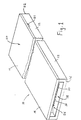
- FIGs 1 and 2 An apparatus 10 for separating hematocrit from a whole blood sample according to the present invention is shown in FIGs 1 and 2.
- the apparatus includes a body 12 and a cover 14.
- a first end 16 includes an inlet port 18 for receiving a whole blood sample.
- a reaction region 20, generally including a vent 21, is spaced from the inlet port 18 and can be situated adjacent a second end 22.
- At least one capillary pathway 24 has an inlet end 26 coupled to the inlet port 18 and an outlet end 28 coupled to the reaction region 20.
- the capillary pathway 24 is dimensioned sufficiently small to assure transport of blood plasma from the inlet end 26 to the outlet end 28 by capillary pressure to deliver a reaction volume of plasma to the reaction region 20.
- the capillary pathway 24 includes a plurality of obstructions 30, the obstructions 30 having a concave portion 32 facing toward the outlet end 28 of the capillary pathway 24.
- FIGs 3-5 Three possible shapes for the obstructions 30 are shown in FIGs 3-5 in relation to the direction of liquid flow through the capillary pathway 24.
- FIGs 3-5 are not intended to exhaust all possible shapes for the obstructions 30, but merely illustrate shapes having utility in the present invention.
- the obstructions 30 are illustrated to include a concave portion 32, outlined in phantom, facing down stream with respect to the direction of liquid flow. The size of the concave portion 32 should probably be evaluated in relation to the total liquid-containing volume between the obstructions 30 rather than in relation to the size of the obstructions.
- the size of the obstructions 30 is believed to play some role in the performance of the apparatus 10, a greater role is believed to be played by the proportion of concave volume to total liquid-containing volume, which is related to the spacing and arrangement of the obstructions 30 within the capillary pathway 24 as well as the size of the concave portions 32.
- the shape of the concave portion 32 need not include a smooth curve as illustrated in FIGs 3-5, and instead can be angular such as triangular or rectangular.
- the capillary pathway 24 in such a structure 12 can be a rectangular channel about 100 ⁇ m high or less, 2 to 5 mm wide, and up to 70 mm long.
- the channel height and width does not have to be constant throughout the whole length, and can include steps 23 and/or ramps 25 that transition from one channel height or width to another as shown generally in FIG 2.
- Each obstruction 30 preferably extends over the entire height of the pathway 24. It will be appreciated that, in principle, such obstructions should also operate if oriented horizontally rather than vertically in the pathway 24, as illustrated, but that the manufacture of an array of such horizontal obstructions might be difficult.
- the obstructions 30 are vertically oriented and have a diameter of about 50 ⁇ m in the width dimension of the channel. The obstructions 30 are preferably separated from their nearest neighbor by a distance of about 10 ⁇ m.
- the hematocrit separation structures of the present invention can be molded of plastic using micro-injection technology similar to that employed in pre-recorded CDs and DVDs.
- the process is outlined in FIGs 6A through 6E.
- a master tool 40 is produced in silicon by using a deep reactive ion etching process.
- the master tool 40 is shown in FIG 6A to include the floor 42 and the side walls 44 of the channel defining the capillary pathway 24.
- the floor 42 in the master tool 40 includes the master structures 46 that reflect the obstructions 30 of the present invention.
- the master tool 40 is then employed to create in FIG 6B one or more working negative tools 48, generally constructed of nickel, that can be employed in the subsequent steps of the manufacturing process.
- a working negative tool 48 is then mounted to a mold tool support fixture 50 as shown in FIG 6C.
- the negative tool 48 and support fixture 50 form a one portion 52 of a mold pair, the other portion 54 being constructed using standard EDM or other machining techniques.
- the two mold portion 52 and 54 can then be operated in an micro-injection molding machine to define a cavity 56 for receiving plastic resin, such as a polycarbonate, to form an apparatus 10 in accordance with the present invention.
- the body 12 and cover 14 will be formed at the same time in the same process in adjacent mold sections to facilitate assembly of the apparatus 10.
- the body 12 and cover 14 Prior to assembly, the body 12 and cover 14 will usually be subjected to a suitable hydrophilizing process covering at least the capillary pathway 24 and reaction region 20.
- a suitable hydrophilizing process covering at least the capillary pathway 24 and reaction region 20.
- the selection of the particular process is generally suggested by, if not dictated by, the resin employed to manufacture the apparatus 10.
- the process can be physical, such as plasma etching, or chemical, such as an application of DONS solution.
- a desired reagent can be added into the reaction region 20.
- the cover 14 is then fixed in place to the body 12 by suitable means such as by mechanical coupling or by solvent or ultrasonic bonding.
- the apparatus 10 can be employed as a clinical diagnostic device to detect an analyte such as blood sugar level in blood plasma.
- a suitable, generally dry reagent is provided in the reaction region 20 to interact with any plasma that passes through the capillary pathway 24.
- a whole blood specimen is applied to the inlet port 18 and the specimen is pulled down the length of the capillary pathway 24 by capillary pressure.
- the specimen proceeds through the capillary pathway 24, it encounters the plurality of obstruction 30, each obstruction having a concave portion 32 on the back side or down stream side.
- hematocrit is observed to collect in the concave portions 32 in an amount exceed the average concentration in the specimen.
- the concentration of hematocrit in the specimen diminishes as it proceeds through the capillary pathway toward the reaction region 20.
- the plasma wets and reacts with the reagent.
- the reaction can be observed through the body 12 or the cover 14 with at least a reduced interference from any hematocrit still remaining in the sample.
- the observations can be made optically, electrically, or by other means suitable to quantitatively evaluate the reaction results.
Abstract
Description
- The present invention is directed to physical structures and methods for separating hematocrit out of small volume whole blood samples leaving merely the plasma or plasma containing a substantially reduced partial volume of hematocrit. The present invention is particularly directed to such structures having no moving parts which subsequent to separation of the plasma would facilitate contacting the reduced hematocrit content plasma with a dry reagent to permit an accurate detection of an analyte.
- Many diagnostic tests are carried out in the clinical field utilizing a blood sample. It is desirable, when possible, to use a very small volumes of blood, often no more than a drop or two. Capillary structures are often employed when handling such small volumes of blood or other fluids. The presence of the hematocrit in the blood sample often interferes with accurate testing and so the removal of, or reduction in concentration of, the hematocrit in the sample, leaving a reduced hematocrit content plasma for testing, is often desirable or even necessary. The removal of the hematocrit is often done using a filter. An example of such a filter device employing capillary structures is described in Hillman, et al., U.S. Patents 4,753,776 and 5,135,719. Other devices employing capillary structures to handle whole blood samples are disclosed in McDonald, et al., U.S. Patent 5,039,617; Hillman, et al., U.S. Patent 4,963,498; and Columbus, U.S. Patent 4,271,119.
- While such filter devices generally perform satisfactorily, many filter materials tend to absorb a significant portion of the plasma from the blood sample thus leaving only a small volume of the reduced plasma for analytical testing. As the total volume of the sample is diminished, the proportion of the plasma fraction that is absorbed by the filter tends to increase leaving even smaller volumes for testing. It is therefore desirable to construct alternative means for removing hematocrit from whole blood that would be usable on very small sample volumes.
- A capillary hematocrit separation structure according to the present invention is included within a housing having a fluid inlet port, a vented reaction region, and a capillary pathway connecting the inlet port and the reaction region. The capillary pathway is dimensioned so that the driving force for the movement of liquid through the capillary pathway arises from capillary pressure. A plurality of obstructions are fixed in the capillary pathway, each obstruction having a concave portion facing toward the vented reaction region. The situation of the concave portion is to be understood, in reference to the flow of liquid from the fluid inlet port to the reaction region, to be positioned on the down stream side of the obstructions.
- The obstructions can take on a variety of shapes including a bullet shape and a quarter moon shape, a ¾ quarter moon shape being preferred. The obstructions are to be situated far enough from each other so that their mere proximity to each other does not create a filter effect, yet they are to be situated close enough to each other as to minimize the volume of liquid retained in the capillary pathway. Preferably, the obstructions are separated from each other, on a nearest neighbor basis, by about 10-5 meters, and arranged in a hexagonal close-pack configuration.
- The number of obstructions to be employed is determined by the capacity of the concave portions of the obstructions. It has been observed that as whole blood flows through a capillary pathway containing a plurality of obstructions in accordance with the present invention, hematocrit collects in the concave portions of the obstructions. While it was initially thought that the hematocrit collected by virtue of Von Karmen vortices, it has now been determined that such vortices only occur in turbulent flow circumstances, and the passage of blood through a capillary channel is probably laminar. The mechanism behind this effect has not been identified, but the effect is significant enough to permit substantial reduction in the partial volume of hematocrit in whole blood samples.
- It is desirable that sufficient obstructions are employed to provide concave portions having a total volume exceeding the volume of hematocrit in the expected sample size. In a preferred embodiment the volume of each concave portion is about 10-13 to 10-14 m3, or 10-4 to 10-5 µl. A sample comprising a single drop of blood typically has a volume of 20 to 50 µl., of which typically 35% to 45% constitutes hematocrit. Even smaller volumes of whole blood are often used by diabetics and others during testing, the smaller volume being achieved by expressing the blood sample from a small cut or puncture, in which case the volume of the sample may amount to only 2 to 10µl. A capillary hematocrit separation structure according to the present invention capable of separating the hematocrit from a single drop sample size includes about 104 to 105 obstructions. A capillary pathway in such a structure can be a rectangular channel about 100 µm high or less, 2 to 5 mm wide, and up to 70 mm long.
- It is to be understood that the number of capillary pathways between the fluid inlet port and the reaction region is not critical and that one or more than one can be employed, if desirable, to facilitate to the construction of the obstructions or other features of the device. While the hematocrit is observed to preferentially accumulate in the concave portions, it is also observed to accumulate to a lesser extent in other regions of the structure, particularly adjacent to the walls defining the capillary pathway.
- A capillary hematocrit separation structure according to the present invention can be molded as two pieces of a thermoplastic resin such as nylon, styrene-acrylic copolymer, polystyrene, or polycarbonate using known micro-injection molding processes. The mold for making the obstructions in the capillary pathway can be constructed by deep reactive ion etching processes typically employed in the manufacture of molds for pre-recorded compact disks and digital video disks. A reaction region is generally also formed by the same process at an outlet end of the capillary pathway which is generally vented to ensure that there is no opposition to the fast capillary flow of liquid through the capillary pathway. The capillary pathway and the reaction region in the molded structure is then preferably subjected to a hydrophilizing process such as by plasma etching or DONS solution. A suitable dry reagent can be situated in the reaction region, if desired. The pieces of the structure are then assembled so that the capillary pathway and reaction region are enclosed within the structure, yet can be accessed at an inlet port designed to receive a sample of blood.
- The resulting structure can be viewed as an apparatus for separating hematocrit from a whole blood sample having a selected total volume, the sample including a partial volume of blood plasma and a partial volume of hematocrit. The fundamental features of the apparatus comprise a body having an inlet port for receiving a whole blood sample, a vented reaction region spaced from the inlet port, and at least one capillary pathway having an inlet end coupled to the inlet port and an outlet end coupled to the vented reaction region, each capillary pathway being dimensioned sufficiently small to assure transport of blood plasma from the inlet end to the outlet end by capillary pressure delivering a reaction volume of plasma to the reaction region, each capillary pathway including a plurality of obstructions, each of the obstructions having a concave portion facing toward the outlet end of the pathway, the sum of the concave portions having sufficient volume to contain at least an appreciable fraction of the hematocrit partial volume.
- Other advantageous features will become apparent upon consideration of the following description of preferred embodiments which references the attached drawings.
-
- FIG. 1 is a perspective view of a capillary hematocrit separation structure according to the present invention.
- FIG. 2 is a plan view of the capillary hematocrit separation structure shown in FIG 1 with the cover removed.
- FIG. 3 is a detail view of a portion of the capillary pathway in the capillary hematocrit separation structure shown in FIG 1 showing a first preferred embodiment for the obstructions.
- FIG. 4 is another detail view of a portion of the capillary pathway showing an alternative embodiment for the obstructions.
- FIG. 5 is yet another detail view of a portion of the capillary pathway showing another alternative embodiment for the obstructions.
- FIGs. 6A-6E schematically illustrate the preferred method for creating the capillary hematocrit separation structures of the present invention.
-
- An
apparatus 10 for separating hematocrit from a whole blood sample according to the present invention is shown in FIGs 1 and 2. The apparatus includes abody 12 and acover 14. Afirst end 16 includes aninlet port 18 for receiving a whole blood sample. Areaction region 20, generally including avent 21, is spaced from theinlet port 18 and can be situated adjacent asecond end 22. At least onecapillary pathway 24 has aninlet end 26 coupled to theinlet port 18 and anoutlet end 28 coupled to thereaction region 20. Thecapillary pathway 24 is dimensioned sufficiently small to assure transport of blood plasma from theinlet end 26 to theoutlet end 28 by capillary pressure to deliver a reaction volume of plasma to thereaction region 20. Thecapillary pathway 24 includes a plurality ofobstructions 30, theobstructions 30 having aconcave portion 32 facing toward theoutlet end 28 of thecapillary pathway 24. - Three possible shapes for the
obstructions 30 are shown in FIGs 3-5 in relation to the direction of liquid flow through thecapillary pathway 24. FIGs 3-5 are not intended to exhaust all possible shapes for theobstructions 30, but merely illustrate shapes having utility in the present invention. In all three shapes theobstructions 30 are illustrated to include aconcave portion 32, outlined in phantom, facing down stream with respect to the direction of liquid flow. The size of theconcave portion 32 should probably be evaluated in relation to the total liquid-containing volume between theobstructions 30 rather than in relation to the size of the obstructions. While, the size of theobstructions 30 is believed to play some role in the performance of theapparatus 10, a greater role is believed to be played by the proportion of concave volume to total liquid-containing volume, which is related to the spacing and arrangement of theobstructions 30 within thecapillary pathway 24 as well as the size of theconcave portions 32. The shape of theconcave portion 32 need not include a smooth curve as illustrated in FIGs 3-5, and instead can be angular such as triangular or rectangular. - The
capillary pathway 24 in such astructure 12 can be a rectangular channel about 100 µm high or less, 2 to 5 mm wide, and up to 70 mm long. The channel height and width does not have to be constant throughout the whole length, and can includesteps 23 and/or ramps 25 that transition from one channel height or width to another as shown generally in FIG 2. Eachobstruction 30 preferably extends over the entire height of thepathway 24. It will be appreciated that, in principle, such obstructions should also operate if oriented horizontally rather than vertically in thepathway 24, as illustrated, but that the manufacture of an array of such horizontal obstructions might be difficult. In the preferred embodiment, theobstructions 30 are vertically oriented and have a diameter of about 50µm in the width dimension of the channel. Theobstructions 30 are preferably separated from their nearest neighbor by a distance of about 10µm. - The hematocrit separation structures of the present invention can be molded of plastic using micro-injection technology similar to that employed in pre-recorded CDs and DVDs. The process is outlined in FIGs 6A through 6E. First, a
master tool 40 is produced in silicon by using a deep reactive ion etching process. Themaster tool 40 is shown in FIG 6A to include the floor 42 and theside walls 44 of the channel defining thecapillary pathway 24. The floor 42 in themaster tool 40 includes themaster structures 46 that reflect theobstructions 30 of the present invention. Themaster tool 40 is then employed to create in FIG 6B one or more workingnegative tools 48, generally constructed of nickel, that can be employed in the subsequent steps of the manufacturing process. A workingnegative tool 48 is then mounted to a moldtool support fixture 50 as shown in FIG 6C. Thenegative tool 48 andsupport fixture 50 form a oneportion 52 of a mold pair, theother portion 54 being constructed using standard EDM or other machining techniques. The twomold portion cavity 56 for receiving plastic resin, such as a polycarbonate, to form anapparatus 10 in accordance with the present invention. Generally, thebody 12 and cover 14 will be formed at the same time in the same process in adjacent mold sections to facilitate assembly of theapparatus 10. - Prior to assembly, the
body 12 and cover 14 will usually be subjected to a suitable hydrophilizing process covering at least thecapillary pathway 24 andreaction region 20. The selection of the particular process is generally suggested by, if not dictated by, the resin employed to manufacture theapparatus 10. The process can be physical, such as plasma etching, or chemical, such as an application of DONS solution. Following the hydrophilizing process, a desired reagent can be added into thereaction region 20. Thecover 14 is then fixed in place to thebody 12 by suitable means such as by mechanical coupling or by solvent or ultrasonic bonding. - In use, the
apparatus 10 can be employed as a clinical diagnostic device to detect an analyte such as blood sugar level in blood plasma. Usually, a suitable, generally dry reagent is provided in thereaction region 20 to interact with any plasma that passes through thecapillary pathway 24. A whole blood specimen is applied to theinlet port 18 and the specimen is pulled down the length of thecapillary pathway 24 by capillary pressure. As the specimen proceeds through thecapillary pathway 24, it encounters the plurality ofobstruction 30, each obstruction having aconcave portion 32 on the back side or down stream side. As the specimen proceeds through thepathway 24, hematocrit is observed to collect in theconcave portions 32 in an amount exceed the average concentration in the specimen. As a result, the concentration of hematocrit in the specimen diminishes as it proceeds through the capillary pathway toward thereaction region 20. As the blood plasma containing a reduced concentration of hematocrit arrives at the reaction region, the plasma wets and reacts with the reagent. The reaction can be observed through thebody 12 or thecover 14 with at least a reduced interference from any hematocrit still remaining in the sample. The observations can be made optically, electrically, or by other means suitable to quantitatively evaluate the reaction results. - Although the present invention has been described by reference to the illustrated preferred embodiment, it will be appreciated by those skilled in the art that certain changes and modifications can be made within the scope of the invention as defined by the appended claims.
Claims (14)
- An apparatus (10) for separating hematocrit from a whole blood sample having a selected total volume, the sample including a partial volume of blood plasma and a partial volume of hematocrit, the apparatus comprising:a body (12) having an inlet port (18) for receiving a whole blood sample, a reaction region (20) spaced from the inlet port (18), and at least one capillary pathway (24) having an inlet end (26) coupled to the inlet port (18) and an outlet end (28) coupled to the reaction region(20), each capillary pathway (24) being dimensioned sufficiently small to assure transport of blood plasma from the inlet end (26) to the outlet end (28) by capillary pressure delivering a reaction volume of plasma to the reaction region (20), characterised in that each capillary pathway (24) includes a plurality of obstructions (30), the obstructions (30) having a concave portion (32) facing toward the outlet end (28) of the pathway (24).
- The apparatus of claim 1 wherein the total volume of the concave portions of all of the obstructions is at least equal to the reaction volume times the ratio of said partial volume of the hematocrit to said total volume of the sample.
- The apparatus of claim 1 wherein the at least one capillary pathway volume is less than the sum of said partial volumes of the blood plasma and hematocrit.
- The apparatus of claim 1 wherein the obstructions, in cross-section, have a crescent moon shape.
- The apparatus of claim 1 wherein the obstructions, in cross-section, have a bullet shape.
- The apparatus of claim 1 wherein the obstructions are separated from each other, on a nearest neighbor basis, by about 10-5 meters.
- The apparatus of claim 1 wherein the inlet port volume is less than about 50 µl.
- The apparatus of claim 7 wherein the sum of the inlet port volume and the capillary pathway volume is less than about 20 µl.
- The apparatus of claim 1 wherein the reaction region contains a dry reagent selected to detect an analyte in the blood plasma.
- The apparatus of claim 1 wherein the reaction region includes an optical window permitting optical detection of an analyte in the blood plasma.
- The apparatus of claim 1 wherein the reaction region includes electrochemical apparatus for detection of an analyte in the blood plasma.
- The apparatus of one of the claim 1 to 11 wherein the apparatus being employed as a clinical diagnostic device.
- A method for detecting an analyte in blood plasma comprising the steps of:providing a reagent in a reaction region of a clinical diagnostic device,separating a specimen amount of blood plasma from a whole blood sample by:introducing a whole blood sample containing a partial volume of blood plasma into an inlet end (26) of a capillary pathway (24) leading to the reaction regions (20), characterised in that the capillary pathway (24) containes a plurality of obstructions (30) fixed in the capillary pathway (24), each obstruction (30) having a concave portion (32) facing away from the inlet end (26),allowing sufficient time for the specimen amount of blood plasma to flow through the length of the capillary pathway (24) to the reaction region (20), andobserving the reaction between the blood plasma and the reagent in the reaction region (20) of the device.
- The method of claim 21 further comprising the step of hydrophilizing the capillary pathway and reaction region prior to the introducing step.
Applications Claiming Priority (2)
| Application Number | Priority Date | Filing Date | Title |
|---|---|---|---|
| US428691 | 1995-04-25 | ||
| US09/428,691 US6319719B1 (en) | 1999-10-28 | 1999-10-28 | Capillary hematocrit separation structure and method |
Publications (3)
| Publication Number | Publication Date |
|---|---|
| EP1096254A2 EP1096254A2 (en) | 2001-05-02 |
| EP1096254A3 EP1096254A3 (en) | 2001-06-13 |
| EP1096254B1 true EP1096254B1 (en) | 2005-04-06 |
Family
ID=23699972
Family Applications (1)
| Application Number | Title | Priority Date | Filing Date |
|---|---|---|---|
| EP00123020A Expired - Lifetime EP1096254B1 (en) | 1999-10-28 | 2000-10-24 | Capillary hematocrit separation structure and method |
Country Status (6)
| Country | Link |
|---|---|
| US (1) | US6319719B1 (en) |
| EP (1) | EP1096254B1 (en) |
| JP (1) | JP4520620B2 (en) |
| AT (1) | ATE292799T1 (en) |
| CA (1) | CA2324131C (en) |
| DE (1) | DE60019228T2 (en) |
Cited By (3)
| Publication number | Priority date | Publication date | Assignee | Title |
|---|---|---|---|---|
| WO2009109997A1 (en) | 2008-03-07 | 2009-09-11 | Advanced Microdevices Pvt Ltd | Method and device for particle removal and droplet preparation for qualitative and quantitative bioanalysis |
| EP2375249A2 (en) | 2010-04-09 | 2011-10-12 | F. Hoffmann-La Roche AG | Devices and process for separating plasma from a blood sample |
| WO2016156376A1 (en) | 2015-03-31 | 2016-10-06 | Roche Diagnostics Gmbh | Plasma separation card |
Families Citing this family (66)
| Publication number | Priority date | Publication date | Assignee | Title |
|---|---|---|---|---|
| US6749814B1 (en) | 1999-03-03 | 2004-06-15 | Symyx Technologies, Inc. | Chemical processing microsystems comprising parallel flow microreactors and methods for using same |
| US6406672B1 (en) * | 2000-01-28 | 2002-06-18 | Roche Diagnostics | Plasma retention structure providing internal flow |
| US6555387B1 (en) * | 2000-09-27 | 2003-04-29 | Becton, Dickinson And Company | Method for producing thin liquid samples for microscopic analysis |
| US6814843B1 (en) * | 2000-11-01 | 2004-11-09 | Roche Diagnostics Corporation | Biosensor |
| SE0201738D0 (en) * | 2002-06-07 | 2002-06-07 | Aamic Ab | Micro-fluid structures |
| US20040019300A1 (en) * | 2002-07-26 | 2004-01-29 | Leonard Leslie Anne | Microfluidic blood sample separations |
| JP2005538383A (en) * | 2002-09-10 | 2005-12-15 | プラコア・インコーポレーテッド | Method and apparatus for monitoring platelet function |
| JP4075765B2 (en) * | 2002-10-30 | 2008-04-16 | 日本電気株式会社 | Separation apparatus, manufacturing method thereof, and analysis system |
| JP2004354364A (en) * | 2002-12-02 | 2004-12-16 | Nec Corp | Fine particle manipulating unit, chip mounted with the same and detector, and method for separating, capturing and detecting protein |
| DE10305050A1 (en) * | 2003-02-07 | 2004-08-19 | Roche Diagnostics Gmbh | Analytical test element and method for blood tests |
| JPWO2004097393A1 (en) * | 2003-04-28 | 2006-07-13 | 松下電器産業株式会社 | Filter and biosensor equipped with the filter |
| EP1642124B1 (en) * | 2003-06-20 | 2017-11-29 | Roche Diabetes Care GmbH | Electrochemical biosensors |
| PL1642117T3 (en) * | 2003-06-20 | 2018-11-30 | F.Hoffmann-La Roche Ag | Reagent stripe for test strip |
| US8679853B2 (en) | 2003-06-20 | 2014-03-25 | Roche Diagnostics Operations, Inc. | Biosensor with laser-sealed capillary space and method of making |
| US8071030B2 (en) * | 2003-06-20 | 2011-12-06 | Roche Diagnostics Operations, Inc. | Test strip with flared sample receiving chamber |
| DE10352535A1 (en) * | 2003-11-07 | 2005-06-16 | Steag Microparts Gmbh | A microstructured separator and method of separating liquid components from a liquid containing particles |
| GB0329220D0 (en) * | 2003-12-17 | 2004-01-21 | Inverness Medical Switzerland | System |
| DE102004027422A1 (en) * | 2004-06-04 | 2005-12-29 | Boehringer Ingelheim Microparts Gmbh | Device for receiving blood and separating blood components |
| JP2007523355A (en) * | 2004-08-21 | 2007-08-16 | エルジー・ライフ・サイエンシズ・リミテッド | Microfluidic device and diagnostic and analytical apparatus including the same |
| WO2006031095A1 (en) * | 2004-09-13 | 2006-03-23 | Leja Holding B.V. | Capillary-loading slide and method of microscopic research with correction of the serge silberberg effect |
| US20060269978A1 (en) * | 2005-04-25 | 2006-11-30 | Haworth William S | Method and device for monitoring platelet function |
| DE102005048236A1 (en) * | 2005-10-07 | 2007-04-12 | Ministerium für Wissenschaft, Forschung und Kunst Baden-Württemberg | Apparatus and method for determining the volume fractions of the phases in a suspension |
| JP2007309741A (en) * | 2006-05-17 | 2007-11-29 | Olympus Corp | Blood separation method and blood separator |
| DE102006025477B4 (en) | 2006-05-30 | 2009-01-15 | Ekf - Diagnostic Gmbh | Cuvette and process for its preparation |
| WO2008070324A2 (en) * | 2006-10-25 | 2008-06-12 | Placor, Inc. | Methods and devices for monitoring platelet function |
| KR100897524B1 (en) | 2006-12-04 | 2009-05-15 | 한국전자통신연구원 | Micro filtration device for the separation of blood plasma |
| JP5309312B2 (en) * | 2007-11-01 | 2013-10-09 | Jfeテクノス株式会社 | Microchip, microchip device and evaporation operation method using microchip |
| JP5438351B2 (en) * | 2009-03-30 | 2014-03-12 | Jfeテクノス株式会社 | Method and apparatus for dispensing labeled compound for PET using microchip |
| SG184592A1 (en) * | 2011-03-18 | 2012-10-30 | Univ Singapore | Isolating target cells from a biological fluid |
| JP5490492B2 (en) * | 2009-10-30 | 2014-05-14 | 学校法人立命館 | Plasma separator and blood analyzer |
| US9372134B2 (en) * | 2010-04-15 | 2016-06-21 | Cytogen Co., Ltd. | Microfluidic device and method for isolating target using same |
| US20110301049A1 (en) * | 2010-06-04 | 2011-12-08 | The Government Of The United States Of America, As Represented By The Secretary Of The Navy | Fluid Flow Contour Control Using Flow Resistance |
| TWI439689B (en) | 2010-09-23 | 2014-06-01 | Bionime Corp | Electrochemical test specimen |
| RU2477645C1 (en) * | 2011-08-24 | 2013-03-20 | Российская Федерация, от имени которой выступает Министерство промышленности и торговли Российской Федерации (Минпромторг России) | Device to separate particles from fluid |
| EP2587248A1 (en) * | 2011-10-25 | 2013-05-01 | Koninklijke Philips Electronics N.V. | Filtering particles from blood or other media |
| WO2013082273A1 (en) | 2011-11-30 | 2013-06-06 | Wellstat Diagnostics, Llc. | Filtration module |
| JP6073072B2 (en) * | 2012-04-27 | 2017-02-01 | 株式会社キコーコーポレーション | Filtration device using nanofiber nonwoven fabric |
| US9081001B2 (en) | 2012-05-15 | 2015-07-14 | Wellstat Diagnostics, Llc | Diagnostic systems and instruments |
| US9213043B2 (en) | 2012-05-15 | 2015-12-15 | Wellstat Diagnostics, Llc | Clinical diagnostic system including instrument and cartridge |
| US9625465B2 (en) | 2012-05-15 | 2017-04-18 | Defined Diagnostics, Llc | Clinical diagnostic systems |
| US9921141B2 (en) * | 2012-08-08 | 2018-03-20 | Koninklijke Philips N.V. | Centrifugal microfluidic device and methods of use |
| US9535082B2 (en) | 2013-03-13 | 2017-01-03 | Abbott Laboratories | Methods and apparatus to agitate a liquid |
| US10058866B2 (en) | 2013-03-13 | 2018-08-28 | Abbott Laboratories | Methods and apparatus to mitigate bubble formation in a liquid |
| USD978375S1 (en) | 2013-03-13 | 2023-02-14 | Abbott Laboratories | Reagent container |
| USD962471S1 (en) | 2013-03-13 | 2022-08-30 | Abbott Laboratories | Reagent container |
| WO2014140172A1 (en) | 2013-03-15 | 2014-09-18 | Roche Diagnostics Gmbh | Methods of failsafing electrochemical measurements of an analyte as well as devices, apparatuses and systems incorporating the same |
| KR101743382B1 (en) | 2013-03-15 | 2017-06-02 | 에프. 호프만-라 로슈 아게 | Methods of detecting high antioxidant levels during electrochemical measurements and failsafing an analyte concentration therefrom as well as devices, apparatuses and systems incorporting the same |
| CA2900694C (en) | 2013-03-15 | 2017-10-24 | F. Hoffmann-La Roche Ag | Methods of using information from recovery pulses in electrochemical analyte measurements as well as devices, apparatuses and systems incorporating the same |
| EP3385707A1 (en) | 2013-03-15 | 2018-10-10 | Roche Diabetes Care GmbH | Methods of scaling data used to construct biosensor algorithms as well as devices, apparatuses and systems incorporating the same |
| JP6267319B2 (en) * | 2013-04-15 | 2018-01-24 | ベクトン・ディキンソン・アンド・カンパニーBecton, Dickinson And Company | Biological fluid transfer device and biological fluid sampling system |
| CA2909183C (en) | 2013-04-15 | 2020-08-04 | Craig A. Gelfand | Blood sampling transfer device |
| JP6367923B2 (en) | 2013-04-15 | 2018-08-01 | ベクトン・ディキンソン・アンド・カンパニーBecton, Dickinson And Company | Body fluid collection device and body fluid separation and inspection system |
| JP6298151B2 (en) | 2013-04-15 | 2018-03-20 | ベクトン・ディキンソン・アンド・カンパニーBecton, Dickinson And Company | Biological fluid sampling device |
| WO2014172246A1 (en) | 2013-04-15 | 2014-10-23 | Becton, Dickinson And Company | Biological fluid sampling transfer device and biological fluid separation and testing system |
| BR112015026246B1 (en) | 2013-04-15 | 2022-10-18 | Becton, Dickinson And Company | BLOOD COLLECTION TRANSFER DEVICE, BLOOD SEPARATION AND TESTING SYSTEM AND BLOOD COLLECTION TRANSFER SYSTEM |
| US9380972B2 (en) | 2013-04-15 | 2016-07-05 | Becton, Dickinson And Company | Biological fluid collection device and biological fluid collection and testing system |
| CA3026548C (en) | 2013-04-15 | 2022-01-04 | Becton, Dickinson And Company | Medical device for collection of a biological sample |
| CA2909355C (en) | 2013-04-15 | 2018-07-10 | Becton, Dickinson And Company | Biological fluid collection device and biological fluid separation and testing system |
| EP2986383B1 (en) | 2013-04-15 | 2020-08-26 | Becton, Dickinson and Company | Biological fluid separation device and biological fluid separation and testing system |
| US10238325B2 (en) | 2013-04-15 | 2019-03-26 | Becton, Dickinson And Company | Medical device for collection of a biological sample |
| EP2986384B1 (en) | 2013-04-15 | 2019-07-17 | Becton, Dickinson and Company | Biological fluid sampling transfer device and biological fluid separation and testing system |
| MX368793B (en) | 2013-04-15 | 2019-10-16 | Becton Dickinson Co | Biological fluid collection device and biological fluid separation and testing system. |
| CA2909233C (en) | 2013-04-15 | 2019-10-22 | Becton, Dickinson And Company | Biological fluid separation device and biological fluid separation and testing system |
| CN112971779A (en) | 2015-08-06 | 2021-06-18 | 贝克顿·迪金森公司 | Biological fluid collection device and biological fluid collection system |
| KR102372113B1 (en) | 2016-10-05 | 2022-03-07 | 에프. 호프만-라 로슈 아게 | Detection reagents and electrode arrangements for multi-analyte diagnostic test elements, and methods of using the same |
| KR101872780B1 (en) * | 2017-01-24 | 2018-06-29 | 광주과학기술원 | Herringbone type fluid guide unit and cell concentrator using the same |
Family Cites Families (46)
| Publication number | Priority date | Publication date | Assignee | Title |
|---|---|---|---|---|
| JPS5113428B1 (en) * | 1970-05-09 | 1976-04-28 | ||
| DE2757384A1 (en) * | 1976-12-29 | 1978-07-06 | Rosemount Inc | FLOWMETER WORKING ACCORDING TO THE PRINCIPLE OF EDBLE RELEASE |
| US4233029A (en) | 1978-10-25 | 1980-11-11 | Eastman Kodak Company | Liquid transport device and method |
| US4271119A (en) | 1979-07-23 | 1981-06-02 | Eastman Kodak Company | Capillary transport device having connected transport zones |
| US4310399A (en) | 1979-07-23 | 1982-01-12 | Eastman Kodak Company | Liquid transport device containing means for delaying capillary flow |
| US4302313A (en) | 1979-07-23 | 1981-11-24 | Eastman Kodak Company | Electrode-containing device with capillary transport between electrodes |
| US4426451A (en) | 1981-01-28 | 1984-01-17 | Eastman Kodak Company | Multi-zoned reaction vessel having pressure-actuatable control means between zones |
| US4473457A (en) | 1982-03-29 | 1984-09-25 | Eastman Kodak Company | Liquid transport device providing diversion of capillary flow into a non-vented second zone |
| US4439526A (en) | 1982-07-26 | 1984-03-27 | Eastman Kodak Company | Clustered ingress apertures for capillary transport devices and method of use |
| US4549952A (en) | 1982-11-22 | 1985-10-29 | Eastman Kodak Company | Capillary transport device having means for increasing the viscosity of the transported liquid |
| US4618476A (en) | 1984-02-10 | 1986-10-21 | Eastman Kodak Company | Capillary transport device having speed and meniscus control means |
| US5140161A (en) | 1985-08-05 | 1992-08-18 | Biotrack | Capillary flow device |
| US5144139A (en) | 1985-08-05 | 1992-09-01 | Biotrack, Inc. | Capillary flow device |
| US4948961A (en) | 1985-08-05 | 1990-08-14 | Biotrack, Inc. | Capillary flow device |
| US5004923A (en) | 1985-08-05 | 1991-04-02 | Biotrack, Inc. | Capillary flow device |
| US4756884A (en) * | 1985-08-05 | 1988-07-12 | Biotrack, Inc. | Capillary flow device |
| US4963498A (en) | 1985-08-05 | 1990-10-16 | Biotrack | Capillary flow device |
| US5204525A (en) | 1985-08-05 | 1993-04-20 | Biotrack | Capillary flow device |
| US5164598A (en) | 1985-08-05 | 1992-11-17 | Biotrack | Capillary flow device |
| US4753776A (en) | 1986-10-29 | 1988-06-28 | Biotrack, Inc. | Blood separation device comprising a filter and a capillary flow pathway exiting the filter |
| US5135719A (en) | 1986-10-29 | 1992-08-04 | Biotrack, Inc. | Blood separation device comprising a filter and a capillary flow pathway exiting the filter |
| US4849340A (en) | 1987-04-03 | 1989-07-18 | Cardiovascular Diagnostics, Inc. | Reaction system element and method for performing prothrombin time assay |
| DE3851458T2 (en) * | 1987-04-08 | 1995-02-09 | Hitachi Ltd | Device with a vaginal flow cell. |
| GB8709882D0 (en) | 1987-04-27 | 1987-06-03 | Genetics Int Inc | Membrane configurations |
| US5051237A (en) * | 1988-06-23 | 1991-09-24 | P B Diagnostic Systems, Inc. | Liquid transport system |
| US5208147A (en) * | 1988-07-21 | 1993-05-04 | Radiometer A/S | Means for measuring a characteristic in a sample fluid |
| US4957582A (en) | 1989-03-16 | 1990-09-18 | Eastman Kodak Company | Capillary transport zone coated with adhesive |
| EP0388782A1 (en) | 1989-03-20 | 1990-09-26 | Quantai Biotronics Inc. | Method for determination of analytes |
| US5039617A (en) | 1989-04-20 | 1991-08-13 | Biotrack, Inc. | Capillary flow device and method for measuring activated partial thromboplastin time |
| CA2020029A1 (en) | 1989-07-12 | 1991-01-13 | Yatin B. Thakore | Device and method for separation of plasma from blood and determination of blood analytes |
| US5135716A (en) | 1989-07-12 | 1992-08-04 | Kingston Diagnostics, L.P. | Direct measurement of HDL cholesterol via dry chemistry strips |
| CA2019865A1 (en) | 1989-07-12 | 1991-01-12 | Yatin B. Thakore | Device and method for separation of fluid components for component testing |
| US5620863A (en) | 1989-08-28 | 1997-04-15 | Lifescan, Inc. | Blood glucose strip having reduced side reactions |
| AU640162B2 (en) | 1989-08-28 | 1993-08-19 | Lifescan, Inc. | Blood separation and analyte detection techniques |
| US5230866A (en) | 1991-03-01 | 1993-07-27 | Biotrack, Inc. | Capillary stop-flow junction having improved stability against accidental fluid flow |
| US5540888A (en) | 1991-11-11 | 1996-07-30 | British Technology Group Limited | Liquid transfer assay devices |
| DE69319427T2 (en) * | 1992-05-01 | 1998-12-10 | Univ Pennsylvania | ANALYSIS OF MEASURING THE FLOW RESISTANCE |
| US5458852A (en) * | 1992-05-21 | 1995-10-17 | Biosite Diagnostics, Inc. | Diagnostic devices for the controlled movement of reagents without membranes |
| US6156270A (en) * | 1992-05-21 | 2000-12-05 | Biosite Diagnostics, Inc. | Diagnostic devices and apparatus for the controlled movement of reagents without membranes |
| US5885527A (en) | 1992-05-21 | 1999-03-23 | Biosite Diagnostics, Inc. | Diagnostic devices and apparatus for the controlled movement of reagents without membrances |
| GB9309797D0 (en) | 1993-05-12 | 1993-06-23 | Medisense Inc | Electrochemical sensors |
| US6113855A (en) * | 1996-11-15 | 2000-09-05 | Biosite Diagnostics, Inc. | Devices comprising multiple capillarity inducing surfaces |
| US5976336A (en) | 1997-04-25 | 1999-11-02 | Caliper Technologies Corp. | Microfluidic devices incorporating improved channel geometries |
| US5798031A (en) | 1997-05-12 | 1998-08-25 | Bayer Corporation | Electrochemical biosensor |
| DE19753849A1 (en) | 1997-12-04 | 1999-06-10 | Roche Diagnostics Gmbh | Analytical test element with a tapered capillary channel |
| GB9907665D0 (en) | 1999-04-01 | 1999-05-26 | Cambridge Molecular Tech | Fluidic devices |
-
1999
- 1999-10-28 US US09/428,691 patent/US6319719B1/en not_active Expired - Fee Related
-
2000
- 2000-10-24 DE DE60019228T patent/DE60019228T2/en not_active Expired - Lifetime
- 2000-10-24 EP EP00123020A patent/EP1096254B1/en not_active Expired - Lifetime
- 2000-10-24 AT AT00123020T patent/ATE292799T1/en not_active IP Right Cessation
- 2000-10-24 CA CA002324131A patent/CA2324131C/en not_active Expired - Fee Related
- 2000-10-27 JP JP2000328528A patent/JP4520620B2/en not_active Expired - Fee Related
Cited By (3)
| Publication number | Priority date | Publication date | Assignee | Title |
|---|---|---|---|---|
| WO2009109997A1 (en) | 2008-03-07 | 2009-09-11 | Advanced Microdevices Pvt Ltd | Method and device for particle removal and droplet preparation for qualitative and quantitative bioanalysis |
| EP2375249A2 (en) | 2010-04-09 | 2011-10-12 | F. Hoffmann-La Roche AG | Devices and process for separating plasma from a blood sample |
| WO2016156376A1 (en) | 2015-03-31 | 2016-10-06 | Roche Diagnostics Gmbh | Plasma separation card |
Also Published As
| Publication number | Publication date |
|---|---|
| EP1096254A2 (en) | 2001-05-02 |
| US6319719B1 (en) | 2001-11-20 |
| JP4520620B2 (en) | 2010-08-11 |
| JP2001183363A (en) | 2001-07-06 |
| EP1096254A3 (en) | 2001-06-13 |
| CA2324131A1 (en) | 2001-04-28 |
| DE60019228T2 (en) | 2006-05-11 |
| CA2324131C (en) | 2007-07-31 |
| ATE292799T1 (en) | 2005-04-15 |
| DE60019228D1 (en) | 2005-05-12 |
Similar Documents
| Publication | Publication Date | Title |
|---|---|---|
| EP1096254B1 (en) | Capillary hematocrit separation structure and method | |
| US7094354B2 (en) | Method and apparatus for separation of particles in a microfluidic device | |
| Weigl et al. | Design and rapid prototyping of thin-film laminate-based microfluidic devices | |
| JP4336834B2 (en) | Chip usage and inspection chip | |
| US6852284B1 (en) | Liquid analysis cartridge | |
| US6451264B1 (en) | Fluid flow control in curved capillary channels | |
| CA2331855C (en) | Plasma retention structure providing internal flow | |
| US8980635B2 (en) | Disposable cartridge for fluid analysis | |
| JP4571129B2 (en) | Method for uniformly applying fluid to reaction reagent area | |
| JP6335802B2 (en) | Liquid sample imaging apparatus and method | |
| US20050249641A1 (en) | Microstructured platform and method for manipulating a liquid | |
| JP2007520693A (en) | Method and apparatus for taking in and storing specimen into microfluidic device | |
| US20040019300A1 (en) | Microfluidic blood sample separations | |
| US20110243794A1 (en) | Biologic fluid analysis cartridge with deflecting top panel | |
| JPH04232855A (en) | Self-measuring-type fluid analyzing tool | |
| JP2007532881A (en) | Disposable chamber for analyzing biological fluids | |
| JP2003510554A (en) | Chemical sensor based on the diffusion of multiple analytes | |
| WO2009146160A1 (en) | Method and apparatus for entry of specimens into a microfluidic device | |
| CN111774104A (en) | Micro-fluidic chip and in-vitro detection device | |
| CA2324129A1 (en) | Moisture-curable compositions containing isocyanate and succinyl urea groups | |
| US10843195B2 (en) | Devices, systems, and methods for specimen preparation using capillary and centrifugal forces | |
| KR101048858B1 (en) | Open groove channel chip | |
| CN212632728U (en) | Micro-fluidic chip and in-vitro detection device | |
| KR102470360B1 (en) | Plasma separation filter for separating plasma from whole blood | |
| JP2009008401A (en) | Blood separation and recovery device |
Legal Events
| Date | Code | Title | Description |
|---|---|---|---|
| PUAI | Public reference made under article 153(3) epc to a published international application that has entered the european phase |
Free format text: ORIGINAL CODE: 0009012 |
|
| PUAL | Search report despatched |
Free format text: ORIGINAL CODE: 0009013 |
|
| 17P | Request for examination filed |
Effective date: 20001024 |
|
| AK | Designated contracting states |
Kind code of ref document: A2 Designated state(s): AT BE CH CY DE DK ES FI FR GB GR IE IT LI LU MC NL PT SE |
|
| AX | Request for extension of the european patent |
Free format text: AL;LT;LV;MK;RO;SI |
|
| AK | Designated contracting states |
Kind code of ref document: A3 Designated state(s): AT BE CH CY DE DK ES FI FR GB GR IE IT LI LU MC NL PT SE |
|
| AX | Request for extension of the european patent |
Free format text: AL;LT;LV;MK;RO;SI |
|
| AKX | Designation fees paid |
Free format text: AT BE CH CY DE DK ES FI FR GB GR IE IT LI LU MC NL PT SE |
|
| 17Q | First examination report despatched |
Effective date: 20040419 |
|
| GRAP | Despatch of communication of intention to grant a patent |
Free format text: ORIGINAL CODE: EPIDOSNIGR1 |
|
| GRAS | Grant fee paid |
Free format text: ORIGINAL CODE: EPIDOSNIGR3 |
|
| GRAA | (expected) grant |
Free format text: ORIGINAL CODE: 0009210 |
|
| AK | Designated contracting states |
Kind code of ref document: B1 Designated state(s): AT BE CH CY DE DK ES FI FR GB GR IE IT LI LU MC NL PT SE |
|
| PG25 | Lapsed in a contracting state [announced via postgrant information from national office to epo] |
Ref country code: IT Free format text: LAPSE BECAUSE OF FAILURE TO SUBMIT A TRANSLATION OF THE DESCRIPTION OR TO PAY THE FEE WITHIN THE PRESCRIBED TIME-LIMIT;WARNING: LAPSES OF ITALIAN PATENTS WITH EFFECTIVE DATE BEFORE 2007 MAY HAVE OCCURRED AT ANY TIME BEFORE 2007. THE CORRECT EFFECTIVE DATE MAY BE DIFFERENT FROM THE ONE RECORDED. Effective date: 20050406 Ref country code: FI Free format text: LAPSE BECAUSE OF FAILURE TO SUBMIT A TRANSLATION OF THE DESCRIPTION OR TO PAY THE FEE WITHIN THE PRESCRIBED TIME-LIMIT Effective date: 20050406 Ref country code: BE Free format text: LAPSE BECAUSE OF FAILURE TO SUBMIT A TRANSLATION OF THE DESCRIPTION OR TO PAY THE FEE WITHIN THE PRESCRIBED TIME-LIMIT Effective date: 20050406 Ref country code: LI Free format text: LAPSE BECAUSE OF FAILURE TO SUBMIT A TRANSLATION OF THE DESCRIPTION OR TO PAY THE FEE WITHIN THE PRESCRIBED TIME-LIMIT Effective date: 20050406 Ref country code: NL Free format text: LAPSE BECAUSE OF FAILURE TO SUBMIT A TRANSLATION OF THE DESCRIPTION OR TO PAY THE FEE WITHIN THE PRESCRIBED TIME-LIMIT Effective date: 20050406 Ref country code: AT Free format text: LAPSE BECAUSE OF FAILURE TO SUBMIT A TRANSLATION OF THE DESCRIPTION OR TO PAY THE FEE WITHIN THE PRESCRIBED TIME-LIMIT Effective date: 20050406 Ref country code: CH Free format text: LAPSE BECAUSE OF FAILURE TO SUBMIT A TRANSLATION OF THE DESCRIPTION OR TO PAY THE FEE WITHIN THE PRESCRIBED TIME-LIMIT Effective date: 20050406 |
|
| REG | Reference to a national code |
Ref country code: GB Ref legal event code: FG4D |
|
| REG | Reference to a national code |
Ref country code: CH Ref legal event code: EP |
|
| REG | Reference to a national code |
Ref country code: IE Ref legal event code: FG4D |
|
| REF | Corresponds to: |
Ref document number: 60019228 Country of ref document: DE Date of ref document: 20050512 Kind code of ref document: P |
|
| PG25 | Lapsed in a contracting state [announced via postgrant information from national office to epo] |
Ref country code: DK Free format text: LAPSE BECAUSE OF FAILURE TO SUBMIT A TRANSLATION OF THE DESCRIPTION OR TO PAY THE FEE WITHIN THE PRESCRIBED TIME-LIMIT Effective date: 20050706 Ref country code: GR Free format text: LAPSE BECAUSE OF FAILURE TO SUBMIT A TRANSLATION OF THE DESCRIPTION OR TO PAY THE FEE WITHIN THE PRESCRIBED TIME-LIMIT Effective date: 20050706 Ref country code: SE Free format text: LAPSE BECAUSE OF FAILURE TO SUBMIT A TRANSLATION OF THE DESCRIPTION OR TO PAY THE FEE WITHIN THE PRESCRIBED TIME-LIMIT Effective date: 20050706 |
|
| PG25 | Lapsed in a contracting state [announced via postgrant information from national office to epo] |
Ref country code: ES Free format text: LAPSE BECAUSE OF FAILURE TO SUBMIT A TRANSLATION OF THE DESCRIPTION OR TO PAY THE FEE WITHIN THE PRESCRIBED TIME-LIMIT Effective date: 20050717 |
|
| PG25 | Lapsed in a contracting state [announced via postgrant information from national office to epo] |
Ref country code: PT Free format text: LAPSE BECAUSE OF FAILURE TO SUBMIT A TRANSLATION OF THE DESCRIPTION OR TO PAY THE FEE WITHIN THE PRESCRIBED TIME-LIMIT Effective date: 20050908 |
|
| NLV1 | Nl: lapsed or annulled due to failure to fulfill the requirements of art. 29p and 29m of the patents act | ||
| REG | Reference to a national code |
Ref country code: CH Ref legal event code: PL |
|
| PG25 | Lapsed in a contracting state [announced via postgrant information from national office to epo] |
Ref country code: CY Free format text: LAPSE BECAUSE OF FAILURE TO SUBMIT A TRANSLATION OF THE DESCRIPTION OR TO PAY THE FEE WITHIN THE PRESCRIBED TIME-LIMIT Effective date: 20051024 |
|
| PLBE | No opposition filed within time limit |
Free format text: ORIGINAL CODE: 0009261 |
|
| STAA | Information on the status of an ep patent application or granted ep patent |
Free format text: STATUS: NO OPPOSITION FILED WITHIN TIME LIMIT |
|
| 26N | No opposition filed |
Effective date: 20060110 |
|
| EN | Fr: translation not filed | ||
| PGFP | Annual fee paid to national office [announced via postgrant information from national office to epo] |
Ref country code: MC Payment date: 20060927 Year of fee payment: 7 |
|
| PGFP | Annual fee paid to national office [announced via postgrant information from national office to epo] |
Ref country code: IE Payment date: 20061011 Year of fee payment: 7 |
|
| PGFP | Annual fee paid to national office [announced via postgrant information from national office to epo] |
Ref country code: GB Payment date: 20061018 Year of fee payment: 7 |
|
| PGFP | Annual fee paid to national office [announced via postgrant information from national office to epo] |
Ref country code: LU Payment date: 20061030 Year of fee payment: 7 |
|
| PG25 | Lapsed in a contracting state [announced via postgrant information from national office to epo] |
Ref country code: MC Free format text: LAPSE BECAUSE OF NON-PAYMENT OF DUE FEES Effective date: 20071031 |
|
| GBPC | Gb: european patent ceased through non-payment of renewal fee |
Effective date: 20071024 |
|
| PG25 | Lapsed in a contracting state [announced via postgrant information from national office to epo] |
Ref country code: IE Free format text: LAPSE BECAUSE OF NON-PAYMENT OF DUE FEES Effective date: 20071024 |
|
| PG25 | Lapsed in a contracting state [announced via postgrant information from national office to epo] |
Ref country code: GB Free format text: LAPSE BECAUSE OF NON-PAYMENT OF DUE FEES Effective date: 20071024 |
|
| PGFP | Annual fee paid to national office [announced via postgrant information from national office to epo] |
Ref country code: FR Payment date: 20071031 Year of fee payment: 8 |
|
| PG25 | Lapsed in a contracting state [announced via postgrant information from national office to epo] |
Ref country code: LU Free format text: LAPSE BECAUSE OF NON-PAYMENT OF DUE FEES Effective date: 20071024 |
|
| PG25 | Lapsed in a contracting state [announced via postgrant information from national office to epo] |
Ref country code: FR Free format text: LAPSE BECAUSE OF NON-PAYMENT OF DUE FEES Effective date: 20081030 |
|
| PGFP | Annual fee paid to national office [announced via postgrant information from national office to epo] |
Ref country code: DE Payment date: 20101029 Year of fee payment: 11 |
|
| PG25 | Lapsed in a contracting state [announced via postgrant information from national office to epo] |
Ref country code: DE Free format text: LAPSE BECAUSE OF NON-PAYMENT OF DUE FEES Effective date: 20120501 |
|
| REG | Reference to a national code |
Ref country code: DE Ref legal event code: R119 Ref document number: 60019228 Country of ref document: DE Effective date: 20120501 |