EP1096216A2 - A method of drying a furnace and/or performing continuous degassing, and plant for implementing the method - Google Patents
A method of drying a furnace and/or performing continuous degassing, and plant for implementing the method Download PDFInfo
- Publication number
- EP1096216A2 EP1096216A2 EP00123036A EP00123036A EP1096216A2 EP 1096216 A2 EP1096216 A2 EP 1096216A2 EP 00123036 A EP00123036 A EP 00123036A EP 00123036 A EP00123036 A EP 00123036A EP 1096216 A2 EP1096216 A2 EP 1096216A2
- Authority
- EP
- European Patent Office
- Prior art keywords
- walls
- furnace
- gas
- plant
- drying
- Prior art date
- Legal status (The legal status is an assumption and is not a legal conclusion. Google has not performed a legal analysis and makes no representation as to the accuracy of the status listed.)
- Granted
Links
Images
Classifications
-
- F—MECHANICAL ENGINEERING; LIGHTING; HEATING; WEAPONS; BLASTING
- F27—FURNACES; KILNS; OVENS; RETORTS
- F27D—DETAILS OR ACCESSORIES OF FURNACES, KILNS, OVENS OR RETORTS, IN SO FAR AS THEY ARE OF KINDS OCCURRING IN MORE THAN ONE KIND OF FURNACE
- F27D99/00—Subject matter not provided for in other groups of this subclass
-
- C—CHEMISTRY; METALLURGY
- C22—METALLURGY; FERROUS OR NON-FERROUS ALLOYS; TREATMENT OF ALLOYS OR NON-FERROUS METALS
- C22B—PRODUCTION AND REFINING OF METALS; PRETREATMENT OF RAW MATERIALS
- C22B9/00—General processes of refining or remelting of metals; Apparatus for electroslag or arc remelting of metals
- C22B9/006—General processes of refining or remelting of metals; Apparatus for electroslag or arc remelting of metals with use of an inert protective material including the use of an inert gas
-
- C—CHEMISTRY; METALLURGY
- C22—METALLURGY; FERROUS OR NON-FERROUS ALLOYS; TREATMENT OF ALLOYS OR NON-FERROUS METALS
- C22B—PRODUCTION AND REFINING OF METALS; PRETREATMENT OF RAW MATERIALS
- C22B9/00—General processes of refining or remelting of metals; Apparatus for electroslag or arc remelting of metals
- C22B9/05—Refining by treating with gases, e.g. gas flushing also refining by means of a material generating gas in situ
-
- F—MECHANICAL ENGINEERING; LIGHTING; HEATING; WEAPONS; BLASTING
- F27—FURNACES; KILNS; OVENS; RETORTS
- F27B—FURNACES, KILNS, OVENS OR RETORTS IN GENERAL; OPEN SINTERING OR LIKE APPARATUS
- F27B3/00—Hearth-type furnaces, e.g. of reverberatory type; Electric arc furnaces ; Tank furnaces
- F27B3/10—Details, accessories or equipment, e.g. dust-collectors, specially adapted for hearth-type furnaces
-
- F—MECHANICAL ENGINEERING; LIGHTING; HEATING; WEAPONS; BLASTING
- F27—FURNACES; KILNS; OVENS; RETORTS
- F27D—DETAILS OR ACCESSORIES OF FURNACES, KILNS, OVENS OR RETORTS, IN SO FAR AS THEY ARE OF KINDS OCCURRING IN MORE THAN ONE KIND OF FURNACE
- F27D1/00—Casings; Linings; Walls; Roofs
- F27D1/16—Making or repairing linings ; Increasing the durability of linings; Breaking away linings
-
- F—MECHANICAL ENGINEERING; LIGHTING; HEATING; WEAPONS; BLASTING
- F27—FURNACES; KILNS; OVENS; RETORTS
- F27D—DETAILS OR ACCESSORIES OF FURNACES, KILNS, OVENS OR RETORTS, IN SO FAR AS THEY ARE OF KINDS OCCURRING IN MORE THAN ONE KIND OF FURNACE
- F27D7/00—Forming, maintaining or circulating atmospheres in heating chambers
- F27D7/02—Supplying steam, vapour, gases or liquids
-
- F—MECHANICAL ENGINEERING; LIGHTING; HEATING; WEAPONS; BLASTING
- F27—FURNACES; KILNS; OVENS; RETORTS
- F27M—INDEXING SCHEME RELATING TO ASPECTS OF THE CHARGES OR FURNACES, KILNS, OVENS OR RETORTS
- F27M2003/00—Type of treatment of the charge
- F27M2003/02—Preheating, e.g. in a laminating line
- F27M2003/025—Drying
Definitions
- the present invention relates to a method of drying a furnace, particularly for the fusion of metals, and to a plant for implementing the method.
- the method is connected with the need to keep metals which are at or above their melting points as free as possible of water. In fact, at these temperatures, any trace of moisture present is transformed into its constituent atomic elements, hydrogen and oxygen, with decidedly adverse effects on the properties of the metal.
- molten aluminium and alloys thereof readily absorb hydrogen which gives rise to porosity due to the presence of gas during subsequent solidification.
- molten copper and alloys thereof absorb oxygen and hydrogen which give rise to defects due to gas reactions during solidification.
- a new furnace or a partially renovated furnace in which some components have been renewed is subjected to several empty heating cycles, before it is actually used, to eliminate the traces of moisture present in its walls which are typically made of refractory material.
- the object of the present invention is therefore to provide a method of drying furnaces which overcomes the disadvantages of the prior art mentioned above.
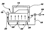
- a furnace for the fusion of metals has walls 10 made of refractory material covered externally by metal plates 12.
- the walls 10 define an internal chamber 14 for holding the metal 16.
- a duct for the supply of substantially dry gas is indicated 18; a plurality of outlet tubes 20 branch from the duct 18 and open in respective holes 22 formed in the covering plates 12 at the lowest points of the walls 10.
- the holes 22 and the associated ends of the outlet tubes 20 advantageously have complementary threads (not visible in the drawing) to permit a leaktight connection.
- the gas is, for example, air, argon, nitrogen or carbon dioxide and may be supplied, in known manner, from bottles or suitable circuits.
- the supply duct 18 has means, generally indicated 24, for regulating the gas-flow, such as valves, pressure reducers, or the like.
- the furnace Before the loading of the metal 16 into the chamber 14 is started, the furnace is subjected to a drying process by the continuous supply of dry gas into the walls 10, from the duct 18 and from the tubes 20, and at a pressure preferably of between 0.5 and 1.5 bar. Since the gas is introduced at the lowest points of the walls 10, it passes through substantially the entire extent of the walls, penetrating the pores of the refractory material, and removes the moisture contained therein, including that which is chemically bound.
- the time required to reduce the moisture present to negligible levels or at least to levels which are not such as to compromise the quality of the metal 16 treated is of the order of two weeks, in comparison with the three months required by conventional drying methods.
- Gas is advantageously also introduced during the operation of the furnace.
- the gas which continues to flow through the walls 10 emerges from the walls by passing through and above the bath of molten metal 16 in order then to leave the furnace through an opening schematically indicated 26 which may, for example, be formed in a loading door.
- the gas thus also removes any traces of moisture contained in the metal 16, as well as the chemical elements resulting from decomposition of moisture. This ensures that the metal 16 remains free of damaging impurities, without the need to perform specific degassing procedures.
Landscapes
- Engineering & Computer Science (AREA)
- Mechanical Engineering (AREA)
- Chemical & Material Sciences (AREA)
- General Engineering & Computer Science (AREA)
- Metallurgy (AREA)
- Materials Engineering (AREA)
- Manufacturing & Machinery (AREA)
- Organic Chemistry (AREA)
- Processing And Handling Of Plastics And Other Materials For Molding In General (AREA)
- Manufacture And Refinement Of Metals (AREA)
- Furnace Details (AREA)
- Drying Of Solid Materials (AREA)
- Fertilizers (AREA)
- Furnace Housings, Linings, Walls, And Ceilings (AREA)
Abstract
Description
Claims (10)
- A method of drying a furnace having walls (10) made of refractory material, particularly for the fusion of metals (16), the method being characterized in that it provides for a flow of substantially dry gas to be introduced into the walls (10) and to be caused to flow through the walls (10) so as to remove the moisture contained therein.
- A method according to Claim 1, characterized in that the gas is introduced at the lowest points of the walls (10).
- A method according to any one of the preceding claims, characterized in that the gas is selected from the group consisting of air, argon, nitrogen and carbon dioxide.
- A method according to any one of the preceding claims, characterized in that the gas is introduced at a pressure of between 0.5 and 1.5 bar.
- A method according to any one of the preceding claims, characterized in that it is performed before the introduction of the metal (16) into the furnace.
- A method according to any one of the preceding claims, characterized in that it is performed after the introduction of the metal (16) into the furnace, during the operation thereof, so that the flow of gas emerging from the walls (10) flows above and through the molten metal (16), removing the moisture contained therein, as well as the atomic elements resulting from decomposition of the moisture.
- A plant for implementing a method of drying a furnace, particularly for the fusion of metals (16), characterized in that it comprises a duct (18) for the supply of substantially dry gas, at least one outlet tube (20) branching from the duct and opening into a respective hole (22) formed in the walls (10) of the furnace.
- A plant according to Claim 7, characterized in that the hole (22) is formed in a metal plate (12) covering the outside of the walls (10) of refractory material.
- A plant according to any one of preceding claims 7 to 8, characterized in that the hole (22) is formed at the lowest point of the walls (10) of the furnace.
- A plant according to any one of preceding claims 7 to 9, characterized in that the supply duct (18) is provided with means (24) for regulating the gas-flow.
Applications Claiming Priority (2)
| Application Number | Priority Date | Filing Date | Title |
|---|---|---|---|
| IT1999TO000931A IT1311258B1 (en) | 1999-10-26 | 1999-10-26 | PROCESS OF DRYING A FURNACE AND / OR CONTINUOUS DEGASSING AND INSTALLATION FOR ITS IMPLEMENTATION. |
| ITTO990931 | 1999-10-26 |
Publications (3)
| Publication Number | Publication Date |
|---|---|
| EP1096216A2 true EP1096216A2 (en) | 2001-05-02 |
| EP1096216A3 EP1096216A3 (en) | 2002-08-21 |
| EP1096216B1 EP1096216B1 (en) | 2009-07-29 |
Family
ID=11418176
Family Applications (1)
| Application Number | Title | Priority Date | Filing Date |
|---|---|---|---|
| EP00123036A Expired - Lifetime EP1096216B1 (en) | 1999-10-26 | 2000-10-24 | A method of drying a furnace and/or performing continuous degassing, and plant for implementing the method |
Country Status (4)
| Country | Link |
|---|---|
| EP (1) | EP1096216B1 (en) |
| AT (1) | ATE438071T1 (en) |
| DE (1) | DE60042633D1 (en) |
| IT (1) | IT1311258B1 (en) |
Cited By (1)
| Publication number | Priority date | Publication date | Assignee | Title |
|---|---|---|---|---|
| IT202000003871A1 (en) * | 2020-02-25 | 2021-08-25 | Smith & Mason Italia S R L | Furnace for aluminum and its alloys, with degassing system for the removal of hydrogen from molten aluminum |
Family Cites Families (4)
| Publication number | Priority date | Publication date | Assignee | Title |
|---|---|---|---|---|
| DE3926786C2 (en) * | 1989-04-14 | 1998-05-20 | Mannesmann Ag | Device for blowing gases into molten metal |
| JPH03217791A (en) * | 1990-01-24 | 1991-09-25 | Nippon Steel Corp | Method and device for drying refractory of molten metal processing vessel |
| JPH0452070A (en) * | 1990-06-15 | 1992-02-20 | Kawasaki Refract Co Ltd | Method for lining molten metal container |
| JPH1136013A (en) * | 1997-07-17 | 1999-02-09 | Harima Ceramic Co Ltd | Drying method for refractory lining |
-
1999
- 1999-10-26 IT IT1999TO000931A patent/IT1311258B1/en active
-
2000
- 2000-10-24 EP EP00123036A patent/EP1096216B1/en not_active Expired - Lifetime
- 2000-10-24 AT AT00123036T patent/ATE438071T1/en not_active IP Right Cessation
- 2000-10-24 DE DE60042633T patent/DE60042633D1/en not_active Expired - Lifetime
Cited By (1)
| Publication number | Priority date | Publication date | Assignee | Title |
|---|---|---|---|---|
| IT202000003871A1 (en) * | 2020-02-25 | 2021-08-25 | Smith & Mason Italia S R L | Furnace for aluminum and its alloys, with degassing system for the removal of hydrogen from molten aluminum |
Also Published As
| Publication number | Publication date |
|---|---|
| ITTO990931A1 (en) | 2001-04-26 |
| EP1096216A3 (en) | 2002-08-21 |
| IT1311258B1 (en) | 2002-03-04 |
| ITTO990931A0 (en) | 1999-10-26 |
| ATE438071T1 (en) | 2009-08-15 |
| DE60042633D1 (en) | 2009-09-10 |
| EP1096216B1 (en) | 2009-07-29 |
Similar Documents
| Publication | Publication Date | Title |
|---|---|---|
| KR20180117648A (en) | Method and apparatus for purifying a target material for an EUV light source | |
| EP0424837A3 (en) | Permeable nozzle method and apparatus for closed feeding of molten metal into twin-belt continuous casting machines | |
| EP1096216B1 (en) | A method of drying a furnace and/or performing continuous degassing, and plant for implementing the method | |
| CN109207758B (en) | Aluminum alloy workpiece smelting and casting process | |
| DE3586277T2 (en) | METHOD AND DEVICE FOR CONTROLLED REFINING OF MELTS. | |
| CA2364356A1 (en) | Process and apparatus for high pressure gas quenching in an atmospheric furnace | |
| KR19990067543A (en) | Method and apparatus for decarburizing steel molten steel | |
| CN202968663U (en) | Multipoint blowing hydrogen removal purification treatment device in aluminium alloy furnace | |
| DE2026780A1 (en) | Method and apparatus for the production of stainless steel | |
| EP0861336B1 (en) | Method for producing pre-treated molten metal castings | |
| JPH10204549A (en) | Non-ferrous metal degas purification equipment | |
| FR2501722A1 (en) | PROCESS FOR PNEUMATIC BREWING OF A METAL BATH | |
| RU2127324C1 (en) | Method of utilizing protective gas in heat treatment of metal in department of bell-type furnaces | |
| JPH0847747A (en) | Copper continuous casting method and apparatus | |
| RU2173235C2 (en) | Method of producing castings from preliminarily treated metal melt | |
| KR100237154B1 (en) | Early vacuum decompression device of molten steel | |
| JPS6173879A (en) | Plating method by vacuum deposition | |
| KR101298532B1 (en) | Apparatus for decreasing defect of strip and method for decreasing defect of strip using the same | |
| CN119614801A (en) | Method for reducing longitudinal cracks on surface of 45 round steel | |
| SU854562A1 (en) | Method of producing ingot | |
| SU1186655A1 (en) | Method of working rail steel outside furnace | |
| DE3711528A1 (en) | Refining and degassing molten steel | |
| JPH10183217A (en) | Slag forming suppression method | |
| JPH01242729A (en) | Electron beam melting method for refractory high-melting-temperature metal material | |
| JP2002153953A (en) | Continuous casting method |
Legal Events
| Date | Code | Title | Description |
|---|---|---|---|
| PUAI | Public reference made under article 153(3) epc to a published international application that has entered the european phase |
Free format text: ORIGINAL CODE: 0009012 |
|
| AK | Designated contracting states |
Kind code of ref document: A2 Designated state(s): AT BE CH CY DE DK ES FI FR GB GR IE IT LI LU MC NL PT SE |
|
| AX | Request for extension of the european patent |
Free format text: AL;LT;LV;MK;RO;SI |
|
| PUAL | Search report despatched |
Free format text: ORIGINAL CODE: 0009013 |
|
| AK | Designated contracting states |
Kind code of ref document: A3 Designated state(s): AT BE CH CY DE DK ES FI FR GB GR IE IT LI LU MC NL PT SE |
|
| AX | Request for extension of the european patent |
Free format text: AL;LT;LV;MK;RO;SI |
|
| RIC1 | Information provided on ipc code assigned before grant |
Free format text: 7F 27D 23/00 A, 7F 27B 3/10 B, 7F 27D 1/16 B, 7F 27D 3/16 B |
|
| 17P | Request for examination filed |
Effective date: 20030221 |
|
| AKX | Designation fees paid |
Designated state(s): AT BE CH CY DE DK ES FI FR GB GR IE IT LI LU MC NL PT SE |
|
| 17Q | First examination report despatched |
Effective date: 20070622 |
|
| GRAP | Despatch of communication of intention to grant a patent |
Free format text: ORIGINAL CODE: EPIDOSNIGR1 |
|
| GRAS | Grant fee paid |
Free format text: ORIGINAL CODE: EPIDOSNIGR3 |
|
| GRAA | (expected) grant |
Free format text: ORIGINAL CODE: 0009210 |
|
| AK | Designated contracting states |
Kind code of ref document: B1 Designated state(s): AT BE CH CY DE DK ES FI FR GB GR IE IT LI LU MC NL PT SE |
|
| REG | Reference to a national code |
Ref country code: GB Ref legal event code: FG4D |
|
| REG | Reference to a national code |
Ref country code: CH Ref legal event code: EP |
|
| REG | Reference to a national code |
Ref country code: IE Ref legal event code: FG4D |
|
| REF | Corresponds to: |
Ref document number: 60042633 Country of ref document: DE Date of ref document: 20090910 Kind code of ref document: P |
|
| NLV1 | Nl: lapsed or annulled due to failure to fulfill the requirements of art. 29p and 29m of the patents act | ||
| PG25 | Lapsed in a contracting state [announced via postgrant information from national office to epo] |
Ref country code: FI Free format text: LAPSE BECAUSE OF FAILURE TO SUBMIT A TRANSLATION OF THE DESCRIPTION OR TO PAY THE FEE WITHIN THE PRESCRIBED TIME-LIMIT Effective date: 20090729 Ref country code: ES Free format text: LAPSE BECAUSE OF FAILURE TO SUBMIT A TRANSLATION OF THE DESCRIPTION OR TO PAY THE FEE WITHIN THE PRESCRIBED TIME-LIMIT Effective date: 20091109 Ref country code: AT Free format text: LAPSE BECAUSE OF FAILURE TO SUBMIT A TRANSLATION OF THE DESCRIPTION OR TO PAY THE FEE WITHIN THE PRESCRIBED TIME-LIMIT Effective date: 20090729 Ref country code: SE Free format text: LAPSE BECAUSE OF FAILURE TO SUBMIT A TRANSLATION OF THE DESCRIPTION OR TO PAY THE FEE WITHIN THE PRESCRIBED TIME-LIMIT Effective date: 20090729 |
|
| PG25 | Lapsed in a contracting state [announced via postgrant information from national office to epo] |
Ref country code: NL Free format text: LAPSE BECAUSE OF FAILURE TO SUBMIT A TRANSLATION OF THE DESCRIPTION OR TO PAY THE FEE WITHIN THE PRESCRIBED TIME-LIMIT Effective date: 20090729 |
|
| PG25 | Lapsed in a contracting state [announced via postgrant information from national office to epo] |
Ref country code: PT Free format text: LAPSE BECAUSE OF FAILURE TO SUBMIT A TRANSLATION OF THE DESCRIPTION OR TO PAY THE FEE WITHIN THE PRESCRIBED TIME-LIMIT Effective date: 20091129 |
|
| PG25 | Lapsed in a contracting state [announced via postgrant information from national office to epo] |
Ref country code: DK Free format text: LAPSE BECAUSE OF FAILURE TO SUBMIT A TRANSLATION OF THE DESCRIPTION OR TO PAY THE FEE WITHIN THE PRESCRIBED TIME-LIMIT Effective date: 20090729 |
|
| PG25 | Lapsed in a contracting state [announced via postgrant information from national office to epo] |
Ref country code: BE Free format text: LAPSE BECAUSE OF FAILURE TO SUBMIT A TRANSLATION OF THE DESCRIPTION OR TO PAY THE FEE WITHIN THE PRESCRIBED TIME-LIMIT Effective date: 20090729 Ref country code: MC Free format text: LAPSE BECAUSE OF NON-PAYMENT OF DUE FEES Effective date: 20091031 |
|
| REG | Reference to a national code |
Ref country code: CH Ref legal event code: PL |
|
| PLBE | No opposition filed within time limit |
Free format text: ORIGINAL CODE: 0009261 |
|
| STAA | Information on the status of an ep patent application or granted ep patent |
Free format text: STATUS: NO OPPOSITION FILED WITHIN TIME LIMIT |
|
| 26N | No opposition filed |
Effective date: 20100503 |
|
| REG | Reference to a national code |
Ref country code: FR Ref legal event code: ST Effective date: 20100630 |
|
| PG25 | Lapsed in a contracting state [announced via postgrant information from national office to epo] |
Ref country code: FR Free format text: LAPSE BECAUSE OF NON-PAYMENT OF DUE FEES Effective date: 20091102 |
|
| PG25 | Lapsed in a contracting state [announced via postgrant information from national office to epo] |
Ref country code: IE Free format text: LAPSE BECAUSE OF NON-PAYMENT OF DUE FEES Effective date: 20091024 Ref country code: GR Free format text: LAPSE BECAUSE OF FAILURE TO SUBMIT A TRANSLATION OF THE DESCRIPTION OR TO PAY THE FEE WITHIN THE PRESCRIBED TIME-LIMIT Effective date: 20091030 Ref country code: LI Free format text: LAPSE BECAUSE OF NON-PAYMENT OF DUE FEES Effective date: 20091031 Ref country code: CH Free format text: LAPSE BECAUSE OF NON-PAYMENT OF DUE FEES Effective date: 20091031 |
|
| PG25 | Lapsed in a contracting state [announced via postgrant information from national office to epo] |
Ref country code: LU Free format text: LAPSE BECAUSE OF NON-PAYMENT OF DUE FEES Effective date: 20091024 |
|
| PG25 | Lapsed in a contracting state [announced via postgrant information from national office to epo] |
Ref country code: CY Free format text: LAPSE BECAUSE OF FAILURE TO SUBMIT A TRANSLATION OF THE DESCRIPTION OR TO PAY THE FEE WITHIN THE PRESCRIBED TIME-LIMIT Effective date: 20090729 |
|
| PGFP | Annual fee paid to national office [announced via postgrant information from national office to epo] |
Ref country code: GB Payment date: 20141022 Year of fee payment: 15 Ref country code: DE Payment date: 20141023 Year of fee payment: 15 |
|
| PGFP | Annual fee paid to national office [announced via postgrant information from national office to epo] |
Ref country code: IT Payment date: 20140911 Year of fee payment: 15 |
|
| REG | Reference to a national code |
Ref country code: DE Ref legal event code: R119 Ref document number: 60042633 Country of ref document: DE |
|
| GBPC | Gb: european patent ceased through non-payment of renewal fee |
Effective date: 20151024 |
|
| PG25 | Lapsed in a contracting state [announced via postgrant information from national office to epo] |
Ref country code: GB Free format text: LAPSE BECAUSE OF NON-PAYMENT OF DUE FEES Effective date: 20151024 Ref country code: IT Free format text: LAPSE BECAUSE OF NON-PAYMENT OF DUE FEES Effective date: 20151024 Ref country code: DE Free format text: LAPSE BECAUSE OF NON-PAYMENT OF DUE FEES Effective date: 20160503 |