EP1096139A1 - Démarreur équipé d'un élément d'amortissement - Google Patents
Démarreur équipé d'un élément d'amortissement Download PDFInfo
- Publication number
- EP1096139A1 EP1096139A1 EP00403007A EP00403007A EP1096139A1 EP 1096139 A1 EP1096139 A1 EP 1096139A1 EP 00403007 A EP00403007 A EP 00403007A EP 00403007 A EP00403007 A EP 00403007A EP 1096139 A1 EP1096139 A1 EP 1096139A1
- Authority
- EP
- European Patent Office
- Prior art keywords
- starter
- housing
- sleeve
- damping element
- nose
- Prior art date
- Legal status (The legal status is an assumption and is not a legal conclusion. Google has not performed a legal analysis and makes no representation as to the accuracy of the status listed.)
- Granted
Links
- 239000007858 starting material Substances 0.000 title claims abstract description 57
- 238000013016 damping Methods 0.000 title claims abstract description 35
- 239000002184 metal Substances 0.000 claims abstract description 21
- 239000000463 material Substances 0.000 claims abstract description 10
- 229920001971 elastomer Polymers 0.000 claims abstract description 3
- 239000000806 elastomer Substances 0.000 claims abstract description 3
- 238000005192 partition Methods 0.000 claims description 9
- 238000002788 crimping Methods 0.000 claims description 4
- 238000004026 adhesive bonding Methods 0.000 claims description 3
- 239000013536 elastomeric material Substances 0.000 claims description 2
- 239000011358 absorbing material Substances 0.000 claims 1
- 229920003023 plastic Polymers 0.000 abstract description 3
- 238000000034 method Methods 0.000 description 5
- 239000003638 chemical reducing agent Substances 0.000 description 4
- 230000000717 retained effect Effects 0.000 description 3
- 239000006096 absorbing agent Substances 0.000 description 2
- 230000008030 elimination Effects 0.000 description 2
- 238000003379 elimination reaction Methods 0.000 description 2
- 230000035939 shock Effects 0.000 description 2
- 230000015572 biosynthetic process Effects 0.000 description 1
- 238000002485 combustion reaction Methods 0.000 description 1
- 229920003052 natural elastomer Polymers 0.000 description 1
- 229920001194 natural rubber Polymers 0.000 description 1
- 239000011359 shock absorbing material Substances 0.000 description 1
- 229920003051 synthetic elastomer Polymers 0.000 description 1
- 230000009466 transformation Effects 0.000 description 1
- 238000003466 welding Methods 0.000 description 1
Images

Classifications
-
- F—MECHANICAL ENGINEERING; LIGHTING; HEATING; WEAPONS; BLASTING
- F02—COMBUSTION ENGINES; HOT-GAS OR COMBUSTION-PRODUCT ENGINE PLANTS
- F02N—STARTING OF COMBUSTION ENGINES; STARTING AIDS FOR SUCH ENGINES, NOT OTHERWISE PROVIDED FOR
- F02N15/00—Other power-operated starting apparatus; Component parts, details, or accessories, not provided for in, or of interest apart from groups F02N5/00 - F02N13/00
Definitions
- the starter drives the crown starting the engine by a drive pinion. How the starter generates a significant noise which is due in particular to the friction of the brushes, reduction, freewheeling ..., but the most important source is caused by meshing of the starter pinion with the starter ring of the engine.
- the vibrations which result from the meshing are communicated to the gearbox output shaft.
- the realization of the rear bearing of the output shaft in plastic material absorbs some of the vibrations.
- another part is transmitted to the front end of the shaft which, via a bearing such a needle bushing is mounted in a housing before the starter nose and it spreads through the starter nose.
- the starter nose is a hollow part with a thin wall, which promotes transformation of mechanical vibrations into acoustic waves, and thus increases the sound level emitted by the starter.
- an axial stop is sometimes placed between the front end of the gearbox output shaft and the axial bottom of the housing. This stop promotes propagation of vibrations from the shaft to the starter nose and thereby increases the noise pollution from the starter.
- the invention proposes a starter of the type comprising a starter frame comprising at least one nose of starter forming a cover and comprising, axially aligned, an electric motor rear which drives a launcher, and of the type in which a launcher shaft has a smooth front section which is guided in rotation, with interposition of a guide bearing, in a housing of the starter nose, characterized in that an element made of material vibration damper is interposed between the guide bearing and the housing of the starter nose.
- the damping element absorbs the vibrations of the shaft starter output and thus limit noise pollution.
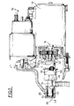
- FIG. 1 represents a motor vehicle starter 10 according to the state of the technique.
- It comprises a chassis in which an electric motor 12 is arranged which drives an armature shaft 14 and a gearbox output shaft 16.
- An axial bore 18 is made in a rear free end of the shaft of reducer outlet 16. It opens into the rear radial face of the free end rear of the output shaft 16 and it is blind at its other front end.
- a smooth front section 20 of the free front end of the output shaft 16 is guided in rotation in a guide bearing 22, which can be a needle bearing, mounted in the blind front housing 24 of a starter nose 26.
- the axial setting of the gearbox output shaft 16 from rear to front is produced by a washer 28 located between the front end of the output shaft 16 and the transverse bottom of the front housing 24.
- a smooth rear section 30 of the rear free end of the output shaft 16 is guided in rotation in a rear guide ring 32 mounted in a housing rear 34.
- the axial setting of the output shaft 16 from front to rear is achieved by a ball disposed at the bottom of the bore 18 of the rear free end of the output shaft reducer 16.
- a force is exerted from front to rear on the output shaft reducer 16 the ball is in contact on the one hand with the free front end of the shaft armature 14 and, on the other hand, with the blind bottom of the bore 18.
- the reduction gear is here with planetary gear which transmits the rotational movement from the armature shaft 14 to the gearbox output shaft 16, it comprises a set of satellites whose axis of rotation is carried by a flange of transverse orientation which is fixed to the rear end section of the gearbox output shaft 16 by a process such as laser, electron bombardment, torch welding plasma, or by bonding or shrinking.
- the satellites are immobilized axially in translation by a plate press fit on the axes of the satellites.
- the reduction gear thus comprises a crown with internal toothing which is fixed, in the assembly shown, by overmolding in a transverse plate fixed on the starter casing.
- a launcher 50 slides axially on a fluted intermediate section 52 of the gearbox output shaft 16, which thus constitutes the starter shaft 48, between a front engagement position and a rear rest position.
- the fluted intermediate section 52 has external grooves which cooperate with internal splines made in the internal axial hole of the launcher 50. When the starter 50 is in the engagement position, the external splines cooperate with internal splines to transmit torque from the starter shaft 48 to pitcher 50.
- the invention makes it possible to reduce the formation of acoustic waves, therefore, by Consequently, the sound level of the starter during its operation.
- a damping element 54 in vibration damping material is interposed between the guide bearing 22 and the front housing 24.
- the damping element 54 performs a mechanical decoupling between the parts which are on either side of its walls. It is made of a material shock absorber such as plastic, natural or synthetic elastomer, etc.
- the damping element 54 is retained axially in the housing 24 by a retaining ring 62 which is crimped at the rear end of the housing 24.
- the damping element 54 is held axially in the housing 24 by an annular plate 55 which has a diameter hole greater than the diameter of the smooth front section 20 and less than the internal diameter of the damping element 54.
- the annular plate 55 is fixed by one or more screws 57, one of which is shown in FIG. 3, on the starter nose 26.
- the damping element 54 is immobilized in the nose of starter 26.by an assembly made tightly radially or by adhesion of the tubular sleeve 56 on the internal wall of the housing 24.
- the envelope 60 is molded directly in the front housing 24. This allows on the one hand to overcome any problems of rigidity of the tubular sleeve 56 and, on the other hand, to remove the retaining ring 62.
- the damping element 54 consists of two pieces.
- FIG. 4 represents them, in a perspective view, before their assembly.
- the damping element 54 consists of the casing 60 made of material shock absorber externally lined by an external metal sleeve 64 also called armature.
- the connection between the metal socket 64 and the casing 60 can be produced by tight mounting, snap-fastening, bonding, or any other process for keeping the two elements in contact.
- the casing 60 can also be molded inside the metal sleeve external 64.
- the external metal sleeve 64 makes it possible to reinforce the envelope 60 which increases the solidity of the damping element 54 and facilitates mounting, such as a tight fitting in the front housing 24.
- the thrust washer 28, the guide bearing 22 and the section smooth front 20 of the free front end of the output shaft 16 are successively introduced into the envelope 60 with its external sleeve 64.
- the assembly thus produced constitutes a sub-assembly which then suffices to be fitted tightly into the housing before 24, the retaining ring 62 as well as the crimping operation are then deleted. You can also mount the element 54 in the front housing 24 then insert the thrust washer 28, the guide bearing 22 and the smooth front section 20.
- the transverse wall front end 58 which closes the sleeve 56 is lined externally by a external metal transverse partition 66 which is made in one piece with the socket external metallic 64.
- the transverse partition 66 makes it possible to stiffen radially the damping element 54.
- the invention consists in lining the tubular sleeve 56 internally with an internal metal sleeve 68.
- the internal metal sleeve 68 strengthens the envelope 60 and removes the contact between the outer ring of the guide bearing 22 with the tubular sleeve 56 made of shock absorbing material.
- the internal metal sleeve 68 is held in the tubular sleeve 56 by a process such as bonding.
- the envelope 60 can also be molded on the ring metallic 68.
- the transverse wall 58 which closes the sleeve 56 is lined internally by a transverse partition internal metal 70 which is produced in one piece with the metal socket 68.
- the damping element 54 can also be a combination of the various previous variants. It is, for example, made up of three parts in accordance with the Figure 8. According to this configuration, the damping element 54 is inserted into the front housing 24, for example by a tight mounting thus removing the ring from retained 62.
- the internal metal transverse partition 70 allows the removal of the washer 28.
- the proposed variants have various advantages such as the reduction of sound level of the starter during its operation, and also, the simplification of the mounting thanks to the elimination of parts such as the washer 28 and the ring retained 62, and the elimination of assembly operations such as the crimping of the ring 62.
Landscapes
- Engineering & Computer Science (AREA)
- Chemical & Material Sciences (AREA)
- Combustion & Propulsion (AREA)
- Mechanical Engineering (AREA)
- General Engineering & Computer Science (AREA)
- Motor Or Generator Frames (AREA)
- Connection Of Motors, Electrical Generators, Mechanical Devices, And The Like (AREA)
- Support Of The Bearing (AREA)
Abstract
Description
- l'élément d'amortissement est constitué d'un manchon tubulaire en matériau amortisseur des vibrations ;
- le manchon est doublé extérieurement par une douille métallique externe ;
- le manchon est doublé intérieurement par une douille métallique interne ;
- l'élément d'amortissement comporte une paroi transversale d'extrémité avant qui ferme le manchon et qui est réalisée en une pièce avec ce dernier ;
- la paroi transversale est doublée extérieurement par une cloison transversale métallique externe réalisée en une pièce avec la douille métallique externe ;
- la paroi transversale est doublée intérieurement par une cloison transversale métallique interne réalisée en une pièce avec la douille métallique interne ;
- le matériau amortisseur est un élastomère ;
- le matériau élastomère est fixé par adhérisation sur au moins une douille métallique ;
- l'élément d'amortissement est fixé par sertissage dans le logement de nez de démarreur ;
- l'élément d'amortissement est fixé par collage dans le logement de nez de démarreur ;
- l'élément d'amortissement est maintenu axialement dans le logement par une plaque annulaire qui fixée par au moins une vis sur le nez de démarreur.
- la figure 1 est une vue en coupe longitudinale partielle d'un démarreur automobile selon l'état de la technique ;
- la figure 2 représente à plus grande échelle la partie avant d'un démarreur équipée d'un élément d'amortissement selon l'invention ;
- la figure 3 représente en détail une réalisation de la fixation de l'élément d'amortissement dans la partie avant du démarreur ;
- la figure 4 représente en perspective à plus grande échelle un élément d'amortissement selon une variante de l'invention ;
- les figures 5 à 8 représentent une vue en coupe longitudinale de l'élément d'amortissement selon des variantes de l'invention.
Claims (12)
- Démarreur (10) du type comportant un châssis de démarreur comportant au moins un nez de démarreur (26) formant capot et comportant, alignés axialement, un moteur électrique arrière qui entraíne un lanceur (50), et du type dans lequel un arbre de lanceur (48) comporte un tronçon avant lisse (20) qui est guidé en rotation, avec interposition d'un palier de guidage (22), dans un logement (24) du nez de démarreur (26), caractérisé en ce qu'un élément (54) en matériau amortisseur des vibrations est interposé entre le palier de guidage (22) et le logement (24) du nez de démarreur (26).
- Démarreur selon la revendication 1, caractérisé en ce que l'élément d'amortissement (54) est constitué d'un manchon tubulaire (56) en matériau amortisseur des vibrations.
- Démarreur selon la revendication précédente, caractérisé en ce que le manchon (56) est doublé extérieurement par une douille métallique externe (64).
- Démarreur selon l'une des revendications 2 ou 3 caractérisé en ce que le manchon est doublé intérieurement par une douille métallique interne (68).
- Démarreur selon l'une des revendications 2 à 4, caractérisé en ce que l'élément d'amortissement (54) comporte une paroi transversale d'extrémité avant (58) qui ferme le manchon (56) et qui est réalisée en une pièce avec ce dernier.
- Démarreur selon la revendication 5 prise en combinaison avec la revendication 3, caractérisé en ce que la paroi transversale (58) est doublée extérieurement par une cloison transversale métallique externe (66) réalisée en une pièce avec la douille métallique externe (64).
- Démarreur selon la revendication 5 prise en combinaison avec la revendication 4, caractérisé en ce que la paroi transversale (58) est doublée intérieurement par une cloison transversale métallique interne (70) réalisée en une pièce avec la douille métallique interne (68).
- Démarreur selon l'une quelconque des revendications précédentes, caractérisé en ce que le matériau amortisseur est un élastomère.
- Démarreur selon la revendication 8 prise en combinaison avec l'une des revendications 3 ou 4, caractérisé en ce que le matériau élastomère est fixé par adhérisation sur au moins une douille métallique (64, 68).
- Démarreur selon l'une quelconque des revendications précédentes, caractérisé en ce que l'élément d'amortissement (54) est fixé par sertissage dans le logement (24) de nez de démarreur (26).
- Démarreur selon l'une quelconque des revendications précédentes, caractérisé en ce que l'élément d'amortissement (54) est fixé par collage dans le logement (24) de nez de démarreur (26).
- Démarreur selon l'une quelconque des revendications précédentes, caractérisé en ce que l'élément d'amortissement (54) est maintenu axialement dans le logement (24) par une plaque annulaire (55) qui est fixée par au moins une vis (57) sur le nez de démarreur (26).
Applications Claiming Priority (2)
| Application Number | Priority Date | Filing Date | Title |
|---|---|---|---|
| FR9913602 | 1999-10-29 | ||
| FR9913602A FR2800421B1 (fr) | 1999-10-29 | 1999-10-29 | Demarreur equipe d'un element d'amortissement |
Publications (2)
| Publication Number | Publication Date |
|---|---|
| EP1096139A1 true EP1096139A1 (fr) | 2001-05-02 |
| EP1096139B1 EP1096139B1 (fr) | 2004-05-19 |
Family
ID=9551540
Family Applications (1)
| Application Number | Title | Priority Date | Filing Date |
|---|---|---|---|
| EP20000403007 Expired - Lifetime EP1096139B1 (fr) | 1999-10-29 | 2000-10-27 | Démarreur équipé d'un élément d'amortissement |
Country Status (3)
| Country | Link |
|---|---|
| EP (1) | EP1096139B1 (fr) |
| DE (1) | DE60010831T2 (fr) |
| FR (1) | FR2800421B1 (fr) |
Citations (2)
| Publication number | Priority date | Publication date | Assignee | Title |
|---|---|---|---|---|
| FR2398190A1 (fr) * | 1977-07-20 | 1979-02-16 | Paris & Du Rhone | Dispositif anti-vibration pour l'arbre d'induit d'un demarreur electrique |
| DE3707600A1 (de) * | 1987-03-10 | 1988-09-22 | Vdo Schindling | Lagerung der motorwelle eines pumpenantriebs |
-
1999
- 1999-10-29 FR FR9913602A patent/FR2800421B1/fr not_active Expired - Lifetime
-
2000
- 2000-10-27 EP EP20000403007 patent/EP1096139B1/fr not_active Expired - Lifetime
- 2000-10-27 DE DE2000610831 patent/DE60010831T2/de not_active Expired - Lifetime
Patent Citations (2)
| Publication number | Priority date | Publication date | Assignee | Title |
|---|---|---|---|---|
| FR2398190A1 (fr) * | 1977-07-20 | 1979-02-16 | Paris & Du Rhone | Dispositif anti-vibration pour l'arbre d'induit d'un demarreur electrique |
| DE3707600A1 (de) * | 1987-03-10 | 1988-09-22 | Vdo Schindling | Lagerung der motorwelle eines pumpenantriebs |
Also Published As
| Publication number | Publication date |
|---|---|
| FR2800421B1 (fr) | 2001-11-30 |
| FR2800421A1 (fr) | 2001-05-04 |
| EP1096139B1 (fr) | 2004-05-19 |
| DE60010831T2 (de) | 2009-10-01 |
| DE60010831D1 (de) | 2004-06-24 |
Similar Documents
| Publication | Publication Date | Title |
|---|---|---|
| EP1058786B1 (fr) | Demarreur de vehicule automobile a reducteur a engrenages comportant des moyens formant amortisseur de torsion | |
| EP4185790A1 (fr) | Boîtier de transmission, groupe motoréducteur et engin roulant équipé d'un tel groupe motoréducteur | |
| EP0243266B1 (fr) | Dispositif de transmission pour véhicule à traction avant | |
| EP1436525B1 (fr) | Reducteur a train epicycloidal notamment pour demarreur de vehicule automobile et demmarreur equipe d'un tel reducteur | |
| EP1096139B1 (fr) | Démarreur équipé d'un élément d'amortissement | |
| EP1200751B1 (fr) | Disque pour embrayage a friction rigide | |
| EP1321350B1 (fr) | Direction assistée électrique pour véhicule automobile | |
| WO2006003285A1 (fr) | Demarreur, notamment de vehicule automobile, equipe d’un lanceur a roue libre par friction | |
| FR2586071A1 (fr) | Volant en plusieurs parties avec amortisseur de vibrations de torsion | |
| FR2745854A1 (fr) | Demarreur de vehicule automobile comportant un pignon d'engrenement sans roue libre | |
| FR2932235A1 (fr) | Dispositif d'accouplement demontable par emboitement elastique. | |
| EP0921307A1 (fr) | Démarreur de véhicule automobile à réducteur à engrenages comportant un dispositif limiteur d'à-coups | |
| EP1318297B1 (fr) | Volant de démarrage anti-bruit | |
| FR2864183A1 (fr) | Dispositif de transmission d'un mouvement de rotation comprenant une gaine formant chemin sinueux pour un arbre flexible | |
| WO2004026664A1 (fr) | Dispositif de suppression des chocs dans un réducteur à vis sans fin et roue tangente | |
| FR2838093A1 (fr) | Arbre intermediaire a fourchette | |
| EP0301965B1 (fr) | Tube-guide pour butée de débrayage de boîte de vitesses de véhicule automobile | |
| FR2665673A3 (fr) | Boite de vitesses pour vehicules a levier de commande insonorise. | |
| FR2875467A1 (fr) | Systeme de direction assistee electrique | |
| FR2729441A1 (fr) | Dispositif pour monter un arbre de sortie dans un carter de transmission de vehicule automobile | |
| FR3082891A1 (fr) | Demarreur comprenant une couronne de reducteur calee axialement | |
| FR2821403A1 (fr) | Volant d'inertie a deux masses pour la ligne de transmission d'un moteur a combustion interne | |
| FR2816677A1 (fr) | Arbre a fourchette, et organe de liaison pour l'assemblage d'un arbre a fourchette | |
| EP3578405B1 (fr) | Ensemble de transmission d'un couple en sortie d'un moteur vers un réducteur et procédé de fabrication associé | |
| WO2019053267A1 (fr) | Dispositif de transmission de couple, amortisseur de torsion et assemblage associe |
Legal Events
| Date | Code | Title | Description |
|---|---|---|---|
| PUAI | Public reference made under article 153(3) epc to a published international application that has entered the european phase |
Free format text: ORIGINAL CODE: 0009012 |
|
| AK | Designated contracting states |
Kind code of ref document: A1 Designated state(s): DE ES GB IT |
|
| AX | Request for extension of the european patent |
Free format text: AL;LT;LV;MK;RO;SI |
|
| 17P | Request for examination filed |
Effective date: 20010330 |
|
| AKX | Designation fees paid |
Free format text: DE ES GB IT |
|
| GRAP | Despatch of communication of intention to grant a patent |
Free format text: ORIGINAL CODE: EPIDOSNIGR1 |
|
| GRAS | Grant fee paid |
Free format text: ORIGINAL CODE: EPIDOSNIGR3 |
|
| GRAA | (expected) grant |
Free format text: ORIGINAL CODE: 0009210 |
|
| AK | Designated contracting states |
Kind code of ref document: B1 Designated state(s): DE ES GB IT |
|
| REG | Reference to a national code |
Ref country code: GB Ref legal event code: FG4D Free format text: NOT ENGLISH |
|
| GBT | Gb: translation of ep patent filed (gb section 77(6)(a)/1977) |
Effective date: 20040519 |
|
| REF | Corresponds to: |
Ref document number: 60010831 Country of ref document: DE Date of ref document: 20040624 Kind code of ref document: P |
|
| PG25 | Lapsed in a contracting state [announced via postgrant information from national office to epo] |
Ref country code: ES Free format text: LAPSE BECAUSE OF FAILURE TO SUBMIT A TRANSLATION OF THE DESCRIPTION OR TO PAY THE FEE WITHIN THE PRESCRIBED TIME-LIMIT Effective date: 20040830 |
|
| PLBE | No opposition filed within time limit |
Free format text: ORIGINAL CODE: 0009261 |
|
| STAA | Information on the status of an ep patent application or granted ep patent |
Free format text: STATUS: NO OPPOSITION FILED WITHIN TIME LIMIT |
|
| 26N | No opposition filed |
Effective date: 20050222 |
|
| PGFP | Annual fee paid to national office [announced via postgrant information from national office to epo] |
Ref country code: GB Payment date: 20171016 Year of fee payment: 18 Ref country code: IT Payment date: 20171011 Year of fee payment: 18 |
|
| GBPC | Gb: european patent ceased through non-payment of renewal fee |
Effective date: 20181027 |
|
| PG25 | Lapsed in a contracting state [announced via postgrant information from national office to epo] |
Ref country code: GB Free format text: LAPSE BECAUSE OF NON-PAYMENT OF DUE FEES Effective date: 20181027 Ref country code: IT Free format text: LAPSE BECAUSE OF NON-PAYMENT OF DUE FEES Effective date: 20181027 |
|
| PGFP | Annual fee paid to national office [announced via postgrant information from national office to epo] |
Ref country code: DE Payment date: 20191009 Year of fee payment: 20 |
|
| REG | Reference to a national code |
Ref country code: DE Ref legal event code: R071 Ref document number: 60010831 Country of ref document: DE |