EP1094700B1 - Endless conveyor - Google Patents
Endless conveyor Download PDFInfo
- Publication number
- EP1094700B1 EP1094700B1 EP99933279A EP99933279A EP1094700B1 EP 1094700 B1 EP1094700 B1 EP 1094700B1 EP 99933279 A EP99933279 A EP 99933279A EP 99933279 A EP99933279 A EP 99933279A EP 1094700 B1 EP1094700 B1 EP 1094700B1
- Authority
- EP
- European Patent Office
- Prior art keywords
- control
- elements
- endless
- hourglass
- endless conveyor
- Prior art date
- Legal status (The legal status is an assumption and is not a legal conclusion. Google has not performed a legal analysis and makes no representation as to the accuracy of the status listed.)
- Expired - Lifetime
Links
Images


Classifications
-
- B—PERFORMING OPERATIONS; TRANSPORTING
- B65—CONVEYING; PACKING; STORING; HANDLING THIN OR FILAMENTARY MATERIAL
- B65G—TRANSPORT OR STORAGE DEVICES, e.g. CONVEYORS FOR LOADING OR TIPPING, SHOP CONVEYOR SYSTEMS OR PNEUMATIC TUBE CONVEYORS
- B65G49/00—Conveying systems characterised by their application for specified purposes not otherwise provided for
- B65G49/05—Conveying systems characterised by their application for specified purposes not otherwise provided for for fragile or damageable materials or articles
-
- B—PERFORMING OPERATIONS; TRANSPORTING
- B65—CONVEYING; PACKING; STORING; HANDLING THIN OR FILAMENTARY MATERIAL
- B65B—MACHINES, APPARATUS OR DEVICES FOR, OR METHODS OF, PACKAGING ARTICLES OR MATERIALS; UNPACKING
- B65B23/00—Packaging fragile or shock-sensitive articles other than bottles; Unpacking eggs
- B65B23/02—Packaging or unpacking eggs
- B65B23/06—Arranging, feeding, or orientating the eggs to be packed; Removing eggs from trays or cartons
-
- A—HUMAN NECESSITIES
- A01—AGRICULTURE; FORESTRY; ANIMAL HUSBANDRY; HUNTING; TRAPPING; FISHING
- A01K—ANIMAL HUSBANDRY; CARE OF BIRDS, FISHES, INSECTS; FISHING; REARING OR BREEDING ANIMALS, NOT OTHERWISE PROVIDED FOR; NEW BREEDS OF ANIMALS
- A01K43/00—Testing, sorting or cleaning eggs ; Conveying devices ; Pick-up devices
Definitions
- the invention relates to an endless conveyor for conveying substantially rotationally-symmetrical products, comprising at least one endless conveying element and a number of transverse elements extending substantially perpendicularly to a conveying direction, wherein the endless conveyor comprises a drive mechanism, wherein at least one hourglass-shaped roller is mounted on each transverse element, such that the hourglass-shaped rollers mounted on the transverse elements located one behind the other extend in one or more rows, said rows extending in the conveying direction.
- Such an apparatus is for instance known from US Patent US-A-4,872,564 and is denoted therein by reference numeral 1.
- such conveyor is referred to by the term 'roller conveyor'.
- the products are nested in the space bounded by two successive rollers of the conveyor.
- each roller of the conveyor bounds two nesting spaces.
- the rollers of the roller conveyor are driven for rotation thereof, causing a product resting on the rollers to rotate as well. This is for instance the case when the product resting on the rollers is to be inspected. In this manner, for instance eggs can be candled and/or checked for breakage in an automatic fashion.
- the center-to-center distance between the successive nesting spaces is particularly large.
- Such large center-to-center distance is undesirable, since the products are generally supplied in close succession and, accordingly, have to be moved apart in order to be conveyed further via the endless conveyor. Since no special facilities have been arranged for moving the products apart, the products will have to undergo a sudden change of velocity, due to the sudden change of distance relative to each other. After all, if the same amount of products have to be fed through per unit of time, while the products have to be located at a larger distance from each other, this can only be effected by increasing the velocity of the products. The sudden increase of velocity of the products is particularly undesirable, in particular in the case of fragile products, such as for instance eggs. The products may break easily, which leads to fouling of the conveyor and the loss of products.
- the object of the invention is to provide an endless conveyor wherein no smearing occurs and wherein, moreover, no sudden increase of velocity of the products fed thereon occurs.
- the endless conveyor of the type described in the preamble is characterized in that the mutual distance between the successive transverse elements in a first path part is smaller than in a second path part, wherein a first control device is provided effecting an increase of distance between the transverse elements at a first transition from the first to the second path part, wherein a second control device is provided effecting a decrease of distance between the transverse elements at a second transition from the second to the first path part, wherein in at least a portion of the second path part, which portion, viewed in conveying direction, extends from the first transition, a support element has moved between each pair of successive hourglass-shaped rollers for supporting the products to be conveyed.
- Such an endless conveyor offers the advantage that the products in the first path part are slightly spaced apart in that, at that location, the mutual distance between the successive transverse elements is less than in the second path part.
- the products lying against each other that are fed to the endless conveyor are received on the first path part of the endless conveyor.
- the products are supported by two successive hourglass-shaped rollers.
- the distance between the hourglass-shaped rollers is increased by means of the second control device.
- a support element is moved between each pair of successive hourglass-shaped rollers, for supporting the products to be conveyed.
- the products to be conveyed rest on an hourglass-shaped roller and a support element.
- the endless conveyor is characterized in that in at least a part of said portion of the second path part, either the hourglass-shaped rollers or the support elements that have moved between the hourglass-shaped rollers are rotatably drivable, while in the first path part, the hourglass-shaped rollers do not rotate.
- each hourglass-shaped roller supports two products, because the hourglass-shaped rollers do not rotate there.
- the hourglass-shaped rollers rotate in the second path part only.
- each hourglass-shaped roller is in contact with only one product, no smearing can occur between the products relative to each other.
- the distance between the hourglass-shaped rollers in the first path part is so small that the smallest ones of a specific type of product keeps resting on two successive hourglass-shaped rollers, while the distance between the hourglass-shaped rollers in the second path part is so large that the largest ones of said specific type of product can move through two successive hourglass-shaped rollers.
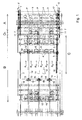
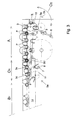
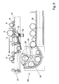
- the exemplary embodiment, shown in Figs. 1 and 2, of an endless conveyor for conveying substantially rotationally-symmetrical products P is in particular intended for conveying eggs P.
- the endless conveyor shown can constitute the transition from a feed-in portion of a sorting and packaging apparatus for eggs P. Lying against one another, the eggs P are fed to the endless conveyor.
- a main function of the endless conveyor is to increase the mutual distance between the eggs P, with this increase of distance taking place in a gradual fashion.
- the endless conveyor comprises at least one endless conveying element 1, 2.
- two endless conveying elements 1, 2 are provided.
- transverse elements 3 which extend substantially perpendicularly to a conveying direction T and are in the present case designed as shafts 3 interconnecting the two endless conveying elements 1, 2.
- the endless conveyor comprises a drive mechanism that is not shown.
- Mounted on each transverse element 3 is at least one hourglass-shaped roller 4.
- six hourglass-shaped rollers 4 are mounted on each transverse element 3, such that the hourglass-shaped rollers 4 mounted on the transverse elements 3 arranged one behind the other, form six rows R1-R6, which rows R1-R6 extend in the conveying direction T.
- the mutual distance between the successive transverse elements 3 in a first path part A is smaller than in a second path part B1-B4.
- the actual conveying part of the endless conveyor is formed by path part A, a portion B1 of path part B1-B4 and a transition O1.
- the other portions B2-B4 of the second path part B1-B4 form a return path B2-B4 along which the transverse elements 3 move in order to move again at an inlet side of the endless conveyor.
- the endless conveyor comprises a first control device 5a which effects an increase of distance between the transverse elements 3 at the location of a first transition O1 from the first A to the second path part B.
- a second control device 5b which effects a decrease of distance between the transverse elements 3 at the location of a second transition 02 from the second B1-B4 to the first path part A.
- a rotationally-symmetrical support element 6 has been moved between each pair of successive hourglass-shaped rollers 4, for supporting the eggs P to be conveyed.
- a guide 14 is arranged at each row R1-R6, which guide, at the first transition 01, comprises a curve path 20 which provides that the support element 6 gradually swivels upwards.
- rotation of a fouled egg P only causes fouling of one hourglass-shaped roller 4 and the support element 6 and no smearing of foul over the other hourglass-shaped rollers 4.
- the rotation is effected in that in the path C, a gear rack 16 is provided.
- Each transverse element 3 comprises a gear 17 which in the path C cooperates with the gear rack 16.
- the distance between the hourglass-shaped rollers 4 in the first path A is such that an egg having a diameter greater than 34 mm keeps resting thereon.
- the distance between the hourglass-shaped rollers 4 is such that each egg having a diameter smaller than 52 mm falls between the rollers. In this manner, it is ensured that in the first path A, even the smallest chicken egg occurring will not fall between the hourglass-shaped rollers 4, whereas in the second path B1, even the largest chicken egg can still fall between two successive hourglass-shaped rollers when the support element 6 located therebetween has temporarily been swiveled away.
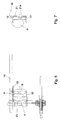
- the first control device 5a of the endless conveyor comprises a number of control elements 7 provided with control slots 8, which control slots 8 each have a slot bottom and an opposite, open, free end, and each define a longitudinal center line of the slot.
- the longitudinal center line of each control slot 8 extends substantially perpendicularly to a direction of travel of the control elements 7 and substantially perpendicularly to the transverse elements 3.
- the control elements 7 travel through a first curve 9, such that each transverse element 3 or part connected thereto that passes into the first transition gradually leaves a slot 8 from the slot bottom of the relevant control slot 8. During this exit movement, the mutual distance between the transverse elements 3 increases.
- the second control device 5b likewise comprises a number of control elements 7 having control slots 8, which control slots 8 each have a slot bottom and an opposite open, free end, and each define a longitudinal center line of the slot.
- the longitudinal center line of each control slot likewise extends substantially perpendicularly to a direction of travel of the control elements 7 and substantially perpendicularly to the transverse elements 3. In the second control device, this last is not necessarily the case, either.
- the control elements 7 follow a second curve 10, such that each transverse element 3 or part connected thereto that passes into the second transition O2 gradually enters a slot 8 from the open end of the relevant control slot 8, while during this entering movement, the mutual distance between the transverse elements 3 decreases.
- the decrease of the distance between the transverse elements 3 can be taken up in that the links of the chain hinge relative to each other.
- the decrease of the distance between the transverse elements 3 can also be taken up in another manner, for instance in that the transverse elements 3 are slidably connected to the endless conveying elements 1, 2.
- the Figures clearly demonstrate that the first and the second control device 5a and 5b respectively are designed as a single, integral control device 5, with the control elements 7 mounted on a single, endless control-conveying element 11 that travels through both the first and the second curve 9 and 10 respectively.
- the endless conveyor is provided with two control devices 5, 5' arranged on either side of the conveying face and each following the first and the second curve 9 and 10 respectively.
- two control devices 5, 5' instead of two single integrated control devices 5, 5', four separate control devices 5a, 5b, 5a', 5b' are also possible.
- the control elements 7 can then for instance be mounted on rotatably arranged disks, the circumference of the relevant disks then defining said first and second curves 9 and 10 respectively.
- each rotationally-symmetrical support element 6 is connected to a leading transverse element 3 via at least one swivel arm 12, 13.
- the two swivel arms 12, 13 are further interconnected by a second support element 21.
- This second support element 21, designed as a rod having a bend 21a, serves to prevent very small eggs from adopting a vertical position between the hourglass-shaped roller and the rotationally-symmetrical support element 6.
- guideways 14 defining the position of the support elements 6 relative to the hourglass-shaped rollers 4.
- each guideway 14 Provided in each guideway 14 is a part 15 that is capable of being swiveled aside and whose position is controllable, so that, if so desired, an egg P resting on an hourglass-shaped roller 4 and a rotationally-symmetrical support element 6 can be released or, conversely, fed through.
- the position of the swivel-aside part 15 in each guideway 14 is controlled by an actuator 18 (see Figs. 1 and 2) associated with the relevant swivel-aside part 15.
- a receiving device by means of which the products removed from the endless conveyor can be further discharged.
- a simple tray 19 is provided.
- a rotatable receiving cage 22 is arranged, for further discharging the released eggs P.
- Fig. 8 clearly demonstrates the operation of such rotatable receiving cage 22.
- the cage 22 comprises a kind of blade wheel 23 rotatable about a shaft 24.
- a guide section 25 extends. Rotation of the blade wheel 23 causes the released eggs to be guided along the guide section 25 and conveyed to the discharging path 26 in a controlled manner.
- the blade wheel 23 further comprises a number of partitions or strips that provide a subdivision, to form, below each row of hourglass-shaped rollers, a compartment in the receiving cage 22 for receiving released eggs therein.
- a transverse element 3 at the first transition O1 gradually moves from the control slot bottom towards the open, free end of the control slot.
- the different positions successively adopted by a transverse element 3 relative to the control slot of a control element 7 traveling through the first curve 9, are designated by 3a, 3b, 3c, 3d, 3e and 3f.
- the mutual distance between the transverse elements 3 gradually increases.
- Reference numerals 3g, 3h, 3i, 3j, 3k and 31 denote successive positions of transverse elements 3 relative to a control slot 8 of a control element 7 traveling through the second curve 10.
- a relevant transverse element 3 gradually moves from the open, free end of the control slot 8 towards the slot bottom, while at the same time, the mutual distance between the transverse elements 3 becomes smaller.
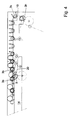
- Fig. 9 shows a partial top plan view of a second exemplary embodiment at the location of the first transition O1 of an endless conveyor according to the invention.
- Fig. 10 shows in side elevation the same portion as represented in Fig. 9.
- the reference numerals used in these Figures refer to parts having the same function as parts from Figs. 1-8 having corresponding reference numerals.
- the most important difference between the first and the second exemplary embodiment is that the control device 5 is provided with two endless control conveying elements 11 each carrying control elements 7, these control conveying elements 11 being arranged under the conveying face instead of on opposite sides of the conveying face.
- the width of the total system is determined by the width of the conveying face, that is, not additionally augmented by the width of the control devices 5, as these control devices 5 are disposed under the conveying face.
- the control elements 7 engage the transverse elements 3 instead of extensions of the transverse elements 3 which extend outside the endless conveying elements 1, 2.
- the exemplary embodiment of Figs. 9 and 10 therefore provides the advantage that the total width of the endless conveyor in question is considerably limited.
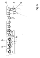
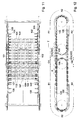
- Figs. 11-17 relate to a third exemplary embodiment of an endless conveyor according to the invention.
- the endless conveying elements 101, 102 which carry the transverse elements 103 with hourglass-shaped rollers 104, are provided with chain links 114 with control slots 108.
- the control cams 109 are disposed on chain links 115 which form part of the control element 105.
- the cams 109 are spaced apart on the endless control element 105 such that the distance between the hourglass-shaped rollers 4 in the first path part A1-A3 is such that an egg having a diameter greater than 34 mm remains resting thereon.
- the endless conveyor further comprises two second endless control elements 106 provided with control cams 110, 111, arranged for engagement of the control slots 108.
- the second control elements 106 extend on either side of the conveying face along the endless conveying elements 101, 102, at the location of the second path part B1-B3 of the endless conveyor.
- the two endless control elements 106 are interconnected by crossbars 112, on which crossbars 112 support elements 107 are mounted.
- the cams 110 move in the control slots 108 of the endless conveying elements 101, 102. Accordingly, the chain links 114 of the endless conveying elements 101, 102 are moved apart, causing the mutual distance between the hourglass-shaped rollers 104 to increase until said mutual distance is such that an egg having a diameter of 52 mm falls between the hourglass-shaped rollers 104.
- support elements 107 are mounted on the crossbars 112 that interconnect the control elements 106, which support elements, at the first transition O1, are moved between the transverse elements 103. In this manner, it is effected that the products P are gradually brought from a slight mutual distance to a greater mutual distance without undergoing a sudden change of speed.
- on each hourglass-shaped roller 104 in the second path part B1 only one product rests, so that during rotation of the roller 104, no smearing can occur between products relative to each other.
- the cam 111 pushes the chain links 114 of the endless conveying elements 101, 102 against one another again, so that they are again at a mutual distance in which the control cams 109 of the first endless control element 105 can readily move in the control slots 108.
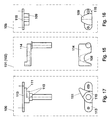
- Fig. 13 is a top plan view of the third exemplary embodiment at the first transition O1, and Fig. 14 shows the same portion in side elevation.
- Fig. 15 is a side elevation and a top plan view, respectively, of the chain links 113 of the second control element.
- first cam 110 and the second cam 111 which are both suitable for engagement in the control slot 108 of the chain link 114 of the endless conveying elements 101, 102, which chain link 114 is shown in detail in Fig. 16.
- the chain link 115 of the first control element 105 is shown in detail in Fig. 17, which likewise represents a top plan view as well as a side elevation, with the cam 109 being clearly visible.
Abstract
Description
Claims (14)
- An endless conveyor for conveying substantially rotationally-symmetrical products (P), comprising at least one endless conveying element (1, 2; 101, 102) and a number of transverse elements (3; 103) extending substantially perpendicularly to a conveying direction, wherein the endless conveyor comprises a drive mechanism, wherein at least one hourglass-shaped roller (4; 104) is mounted on each transverse element (3; 103), such that the hourglass-shaped rollers (4; 104) mounted on the transverse elements (3; 103) located one behind the other extend in one or more rows (R1-R6), said rows (R1-R6) extending in the conveying direction (T), wherein the mutual distance between the successive transverse elements (3; 103) in a first path part (A) is smaller than in a second path part (B1-B4), wherein a first control device (5a; 105) is provided effecting an increase of distance between the transverse elements (3; 103) at a first transition (O1) from the first (A) to the second path part (B), wherein a second control device (5b; 106) is provided effecting a decrease of distance between the transverse elements (3; 103) at a second transition (02) from the second (B) to the first path part (A), wherein in at least a portion (B1) of the second path part (B1-B4), which portion (B1), viewed in conveying direction (T), extends from the first transition (O1), a support element (6; 107) has moved between each pair of successive hourglass-shaped rollers (4) for supporting the products (P) to be conveyed.
- An endless conveyor according to claim 1, characterized in that in at least a part (C) of said portion (B1) of the second path part (B1-B4), either the hourglass-shaped rollers (4; 104) or the support elements (6; 107) that have moved between the hourglass-shaped rollers (4; 104) are rotatably drivable, while in the first path part (A), the hourglass-shaped rollers (4) do not rotate.
- An endless conveyor according to claim 1 or 2, characterized in that the distance between the hourglass-shaped rollers (4; 104) in the first path (A) is so small that the smallest ones of a specific type of product keep resting on two successive hourglass-shaped rollers, wherein the distance between the hourglass-shaped rollers in the second path is so great that the largest ones of said specific type of product can move between two successive hourglass-shaped rollers.
- An endless conveyor according to claim 3, characterized in that the distance between the successive hourglass-shaped rollers (4; 104) in the first path (A) is such that chicken eggs having a diameter of more than about 34 mm do not fall between the rollers (4; 104), wherein the distance between the successive hourglass-shaped rollers (4; 104) in the second path (B) is such that chicken eggs having a diameter of less than about 52 mm do fall between the rollers (4; 104).
- An endless conveyor according to any one of the preceding claims, characterized in that the at least one first control device (5a) comprises a number of control elements (7) provided with control slots (8), said control slots (8) each having a slot bottom and an opposite, open, free end and each defining a longitudinal center line of the slot, wherein at the first transition (O1) the control elements (7) travel through a first curve (9) such that each transverse element (3) or part connected thereto that passes into the first transition (O1), gradually leaves a slot (8) from the slot bottom of the relevant control slot (8), wherein during this exit movement, the mutual distance between the transverse elements (3) increases.
- An endless conveyor according to any one of the preceding claims, characterized in that the at least one second control device (5b) comprises a number of control elements (7) provided with control slots (8), said control slots (8) each having a slot bottom and an opposite, open, free end and each defining a longitudinal center line of the slot, wherein at the second transition (O2) the control elements (7) travel through a second curve (10) such that each transverse element (3) or part connected thereto that passes into the second transition (O2), gradually enters a slot (8) from the open end of the relevant control slot (8), wherein during this entering movement, the mutual distance between the transverse elements (3) decreases.
- An endless conveyor according to claims 5 and 6, characterized in that the at least one first and the at least one second control device (5a, 5a' and 5b, 5b' respectively) are designed as at least one single integral control device (5, 5'), wherein the control elements (7) are mounted on a single endless control-conveying element (11) traveling through both the first and the second curve (9 and 10 respectively).
- An endless conveyor according to any one of the preceding claims, characterized in that each rotationally-symmetrical support element (6) is connected, via at least one swivel arm (12, 13), to a leading or trailing transverse element (3), wherein at least one guideway (14) is provided which defines the position of the support elements (6) relative to the hourglass-shaped rollers (4).
- An endless conveyor according to claim 8, characterized in that in the or each guideway (14), a swivel-aside part (15) is arranged whose position is controllable, so that, if so desired, a product (P) resting on an hourglass-shaped roller (4) and a rotationally-symmetrical support element (6) can be released or fed through.
- An endless conveyor according to claim 9, characterized in that below a portion (B1) of the second path part (B1-B4), at the level of the swivel-aside part (15) in the guideway (14), a receiving cage (22) is arranged provided with a rotatable blade wheel (23) and a guide section (25) extending around at least a part of the outer circumference of the blade wheel (23).
- An endless conveyor according to any one of claims 1-4, characterized in that the endless conveying elements (101, 102) are provided with chain links (114) having control slots (108), wherein at least one first endless control element (105) is provided with control cams (109) arranged for engagement of the control slots (108), wherein the at least one first endless control element (105) extends along the endless conveying elements (101, 102) at the location of the first path (A1-A3).
- An endless conveyor according to any one of claims 1-4 or 11, characterized in that the endless conveying elements (101, 102) are provided with chain links (114) having control slots (108), wherein at least one second endless control element (106) is provided with control cams (110, 111) arranged for engagement of the control slots (108), wherein the at least one second control element (106) extends along the endless conveying elements (101, 102) at the location of the second path (B1-B3).
- An endless conveyor according to claim 12, characterized in that it is provided with two endless control elements (106) extending adjacent endless conveying elements (101, 102), said control elements (106) being interconnected by crossbars (112), on which crossbars the support elements (107) are mounted.
- An endless conveyor according to claim 12 or 13, characterized in that the second endless control elements (106) are provided with chain links (113) which each carry a first cam (110) for keeping the chain links (114) of the endless conveying elements (101, 102) at a distance, wherein the chain links (113) of the second endless control elements (106) each also carry a second cam (111) for moving the chain links (114) of the endless conveying elements (101, 102) towards each other in the second transition (O2).
Applications Claiming Priority (3)
| Application Number | Priority Date | Filing Date | Title |
|---|---|---|---|
| NL1009569A NL1009569C2 (en) | 1998-07-06 | 1998-07-06 | Endless conveyor. |
| NL1009569 | 1998-07-06 | ||
| PCT/NL1999/000419 WO2000001229A1 (en) | 1998-07-06 | 1999-07-05 | Endless conveyor |
Publications (2)
| Publication Number | Publication Date |
|---|---|
| EP1094700A1 EP1094700A1 (en) | 2001-05-02 |
| EP1094700B1 true EP1094700B1 (en) | 2002-01-23 |
Family
ID=19767432
Family Applications (1)
| Application Number | Title | Priority Date | Filing Date |
|---|---|---|---|
| EP99933279A Expired - Lifetime EP1094700B1 (en) | 1998-07-06 | 1999-07-05 | Endless conveyor |
Country Status (11)
| Country | Link |
|---|---|
| US (1) | US6454101B1 (en) |
| EP (1) | EP1094700B1 (en) |
| JP (1) | JP4375904B2 (en) |
| KR (1) | KR100617374B1 (en) |
| AT (1) | ATE212185T1 (en) |
| DE (1) | DE69900822T2 (en) |
| DK (1) | DK1094700T3 (en) |
| ES (1) | ES2172342T3 (en) |
| NL (1) | NL1009569C2 (en) |
| TW (1) | TW466098B (en) |
| WO (1) | WO2000001229A1 (en) |
Families Citing this family (16)
| Publication number | Priority date | Publication date | Assignee | Title |
|---|---|---|---|---|
| KR20040093698A (en) * | 2002-01-29 | 2004-11-08 | 에프피에스 푸드 프로세싱 시스템즈 비.브이. | System and method for washing eggs |
| CN1839077A (en) * | 2003-08-18 | 2006-09-27 | Fps食品加工系统公司 | Apparatus for conveying objects |
| NL1028090C2 (en) * | 2004-01-22 | 2006-01-25 | Food Processing Systems | Supply transporter. |
| NL1026727C2 (en) | 2004-07-26 | 2006-02-02 | Patrick Franciscus J Loosbroek | Beach umbrella. |
| WO2007117140A1 (en) | 2006-04-07 | 2007-10-18 | Fps Food Processing Systems B.V. | Apparatus for feeding eggs |
| ES2358283T3 (en) | 2006-09-01 | 2011-05-09 | Fps Food Processing Systems B.V. | DOSAGE DEVICE. |
| WO2009012135A2 (en) * | 2007-07-17 | 2009-01-22 | Diamond Automations, Inc. | Egg orienting and accumulating system with forward and reverse interconnected conveyors for preventing egg overflow/ride up and prior to exiting in individual rows upon spool bars |
| FR2948926B1 (en) * | 2009-08-06 | 2011-10-21 | Michelin Soc Tech | TRANSITIQUE SUITABLE FOR THE TRANSFER AND STORAGE OF TIRE CARCASES |
| TW201138652A (en) * | 2010-05-05 | 2011-11-16 | jie-wen Zhan | Egg yolk centralizing, aging and cooling device |
| KR101140085B1 (en) * | 2011-08-12 | 2012-05-07 | 공정식 | Apparatus for washing constant velocity joint for car |
| US9358585B2 (en) * | 2013-01-16 | 2016-06-07 | Crary Industries, Inc. | Agricultural article sizer |
| US9521831B2 (en) * | 2013-12-17 | 2016-12-20 | Zoetis Services Llc | Apparatus for removing eggs from egg carriers, and associated method |
| NL2013911B1 (en) * | 2014-12-03 | 2016-10-11 | Aweta G&P B V | Apparatus for singulating products. |
| DE202016102333U1 (en) * | 2016-05-03 | 2016-06-02 | Big Dutchman International Gmbh | Poultry farming system |
| NL2023787B1 (en) * | 2019-09-06 | 2021-05-17 | Hedipack Tech Beheer B V | Packing device for packing eggs |
| CN110844190A (en) * | 2019-11-14 | 2020-02-28 | 广东敬昌中药饮片有限公司 | Fractional packaging equipment for traditional Chinese medicine decoction pieces |
Family Cites Families (8)
| Publication number | Priority date | Publication date | Assignee | Title |
|---|---|---|---|---|
| US2296645A (en) | 1941-07-17 | 1942-09-22 | Fmc Corp | Melon aligning and spacing conveyer |
| US2417921A (en) * | 1944-02-04 | 1947-03-25 | Fmc Corp | Flexibly suspended ball means for advancing articles over transverse assorting rollers |
| US4195736A (en) * | 1978-01-18 | 1980-04-01 | Diamond International Corporation | Egg grading system |
| FR2588842B1 (en) * | 1985-10-21 | 1987-12-31 | Regie Autonome Transports | CONTINUOUS TRANSPORT DEVICE AT VARIABLE SPEED |
| US4872564A (en) | 1987-06-30 | 1989-10-10 | Staalkat B.V. | Method of, and apparatus for, automatically checking eggs for flaws and blemishes, such as cracks, blood, dirt, a leak, aberrant form and the like |
| US4979624A (en) * | 1989-02-24 | 1990-12-25 | Ellis Malcolm P | Sizing apparatus and proportional spacing mechanism |
| NL8901225A (en) * | 1989-05-17 | 1990-12-17 | Staalkat Bv | METHOD AND APPARATUS FOR CHECKING AND PROCESSING OF EGGS |
| US5181596A (en) * | 1990-10-19 | 1993-01-26 | Warkentin A James | Off-loading conveying system |
-
1998
- 1998-07-06 NL NL1009569A patent/NL1009569C2/en not_active IP Right Cessation
-
1999
- 1999-07-02 TW TW088111233A patent/TW466098B/en not_active IP Right Cessation
- 1999-07-05 US US09/743,099 patent/US6454101B1/en not_active Expired - Lifetime
- 1999-07-05 DK DK99933279T patent/DK1094700T3/en active
- 1999-07-05 DE DE69900822T patent/DE69900822T2/en not_active Expired - Lifetime
- 1999-07-05 KR KR1020017000115A patent/KR100617374B1/en not_active IP Right Cessation
- 1999-07-05 ES ES99933279T patent/ES2172342T3/en not_active Expired - Lifetime
- 1999-07-05 EP EP99933279A patent/EP1094700B1/en not_active Expired - Lifetime
- 1999-07-05 AT AT99933279T patent/ATE212185T1/en not_active IP Right Cessation
- 1999-07-05 WO PCT/NL1999/000419 patent/WO2000001229A1/en active IP Right Grant
- 1999-07-05 JP JP2000557687A patent/JP4375904B2/en not_active Expired - Lifetime
Also Published As
| Publication number | Publication date |
|---|---|
| WO2000001229A1 (en) | 2000-01-13 |
| US6454101B1 (en) | 2002-09-24 |
| DE69900822T2 (en) | 2002-08-29 |
| ES2172342T3 (en) | 2002-09-16 |
| DK1094700T3 (en) | 2002-05-06 |
| ATE212185T1 (en) | 2002-02-15 |
| DE69900822D1 (en) | 2002-03-14 |
| JP4375904B2 (en) | 2009-12-02 |
| KR20010071741A (en) | 2001-07-31 |
| EP1094700A1 (en) | 2001-05-02 |
| TW466098B (en) | 2001-12-01 |
| KR100617374B1 (en) | 2006-08-29 |
| JP2002519268A (en) | 2002-07-02 |
| NL1009569C2 (en) | 2000-01-10 |
Similar Documents
| Publication | Publication Date | Title |
|---|---|---|
| EP1094700B1 (en) | Endless conveyor | |
| EP3247202B1 (en) | Endless egg conveyor | |
| EP0098734B1 (en) | Egg handling system | |
| EP3197799B1 (en) | Pop-up conveyor transfer system | |
| US6029424A (en) | High-speed egg processing system and method | |
| EP0576181B1 (en) | Egg collector | |
| US5002016A (en) | Device for collecting eggs | |
| US3552541A (en) | Article handling apparatus | |
| CA1205415A (en) | Apparatus for combining several rows of bottles or similar objects on an inlet conveyor in a single row on an outlet conveyor | |
| NL9002455A (en) | EGG BREAKER. | |
| EP0897760B1 (en) | Conveying device in a container inspection system | |
| NL9100785A (en) | DEVICE FOR TAKING-IN, CASE-TRANSPORTING AND DELIVERING OBJECTS SUCH AS EGGS. | |
| US4293066A (en) | Egg transporting system | |
| JPH10212025A (en) | Transfer device for fragile article such as egg | |
| EP2377763B1 (en) | Apparatus and method for turning eggs | |
| NL8104746A (en) | DEVICE FOR ORGANIZING EGGS. | |
| EP4025507B1 (en) | Packaging device for packaging eggs | |
| SU759080A1 (en) | Apparatus for accumulating trough with sweet bodies to unit for rapid setting | |
| NL2014157B1 (en) | Endless egg conveyor. | |
| GB2064459A (en) | Positioning apparatus and conveying apparatus | |
| JPH09150938A (en) | Device for arranging direction of eggs |
Legal Events
| Date | Code | Title | Description |
|---|---|---|---|
| PUAI | Public reference made under article 153(3) epc to a published international application that has entered the european phase |
Free format text: ORIGINAL CODE: 0009012 |
|
| 17P | Request for examination filed |
Effective date: 20010124 |
|
| AK | Designated contracting states |
Kind code of ref document: A1 Designated state(s): AT BE CH CY DE DK ES FI FR GB GR IE IT LI LU MC NL PT SE |
|
| GRAG | Despatch of communication of intention to grant |
Free format text: ORIGINAL CODE: EPIDOS AGRA |
|
| GRAG | Despatch of communication of intention to grant |
Free format text: ORIGINAL CODE: EPIDOS AGRA |
|
| GRAH | Despatch of communication of intention to grant a patent |
Free format text: ORIGINAL CODE: EPIDOS IGRA |
|
| 17Q | First examination report despatched |
Effective date: 20010608 |
|
| GRAH | Despatch of communication of intention to grant a patent |
Free format text: ORIGINAL CODE: EPIDOS IGRA |
|
| GRAA | (expected) grant |
Free format text: ORIGINAL CODE: 0009210 |
|
| REG | Reference to a national code |
Ref country code: GB Ref legal event code: IF02 |
|
| AK | Designated contracting states |
Kind code of ref document: B1 Designated state(s): AT BE CH CY DE DK ES FI FR GB GR IE IT LI LU MC NL PT SE |
|
| PG25 | Lapsed in a contracting state [announced via postgrant information from national office to epo] |
Ref country code: LI Free format text: LAPSE BECAUSE OF FAILURE TO SUBMIT A TRANSLATION OF THE DESCRIPTION OR TO PAY THE FEE WITHIN THE PRESCRIBED TIME-LIMIT Effective date: 20020123 Ref country code: GR Free format text: LAPSE BECAUSE OF FAILURE TO SUBMIT A TRANSLATION OF THE DESCRIPTION OR TO PAY THE FEE WITHIN THE PRESCRIBED TIME-LIMIT Effective date: 20020123 Ref country code: FI Free format text: LAPSE BECAUSE OF FAILURE TO SUBMIT A TRANSLATION OF THE DESCRIPTION OR TO PAY THE FEE WITHIN THE PRESCRIBED TIME-LIMIT Effective date: 20020123 Ref country code: CH Free format text: LAPSE BECAUSE OF FAILURE TO SUBMIT A TRANSLATION OF THE DESCRIPTION OR TO PAY THE FEE WITHIN THE PRESCRIBED TIME-LIMIT Effective date: 20020123 Ref country code: AT Free format text: LAPSE BECAUSE OF FAILURE TO SUBMIT A TRANSLATION OF THE DESCRIPTION OR TO PAY THE FEE WITHIN THE PRESCRIBED TIME-LIMIT Effective date: 20020123 |
|
| REF | Corresponds to: |
Ref document number: 212185 Country of ref document: AT Date of ref document: 20020215 Kind code of ref document: T |
|
| REG | Reference to a national code |
Ref country code: CH Ref legal event code: EP |
|
| REG | Reference to a national code |
Ref country code: IE Ref legal event code: FG4D |
|
| REF | Corresponds to: |
Ref document number: 69900822 Country of ref document: DE Date of ref document: 20020314 |
|
| PG25 | Lapsed in a contracting state [announced via postgrant information from national office to epo] |
Ref country code: SE Free format text: LAPSE BECAUSE OF FAILURE TO SUBMIT A TRANSLATION OF THE DESCRIPTION OR TO PAY THE FEE WITHIN THE PRESCRIBED TIME-LIMIT Effective date: 20020423 Ref country code: PT Free format text: LAPSE BECAUSE OF FAILURE TO SUBMIT A TRANSLATION OF THE DESCRIPTION OR TO PAY THE FEE WITHIN THE PRESCRIBED TIME-LIMIT Effective date: 20020423 |
|
| REG | Reference to a national code |
Ref country code: DK Ref legal event code: T3 |
|
| PG25 | Lapsed in a contracting state [announced via postgrant information from national office to epo] |
Ref country code: LU Free format text: LAPSE BECAUSE OF NON-PAYMENT OF DUE FEES Effective date: 20020705 Ref country code: IE Free format text: LAPSE BECAUSE OF NON-PAYMENT OF DUE FEES Effective date: 20020705 |
|
| ET | Fr: translation filed | ||
| PG25 | Lapsed in a contracting state [announced via postgrant information from national office to epo] |
Ref country code: CY Free format text: LAPSE BECAUSE OF FAILURE TO SUBMIT A TRANSLATION OF THE DESCRIPTION OR TO PAY THE FEE WITHIN THE PRESCRIBED TIME-LIMIT Effective date: 20020731 |
|
| REG | Reference to a national code |
Ref country code: CH Ref legal event code: PL |
|
| REG | Reference to a national code |
Ref country code: ES Ref legal event code: FG2A Ref document number: 2172342 Country of ref document: ES Kind code of ref document: T3 |
|
| PLBE | No opposition filed within time limit |
Free format text: ORIGINAL CODE: 0009261 |
|
| STAA | Information on the status of an ep patent application or granted ep patent |
Free format text: STATUS: NO OPPOSITION FILED WITHIN TIME LIMIT |
|
| 26N | No opposition filed | ||
| PG25 | Lapsed in a contracting state [announced via postgrant information from national office to epo] |
Ref country code: MC Free format text: LAPSE BECAUSE OF NON-PAYMENT OF DUE FEES Effective date: 20030201 |
|
| REG | Reference to a national code |
Ref country code: IE Ref legal event code: MM4A |
|
| REG | Reference to a national code |
Ref country code: FR Ref legal event code: PLFP Year of fee payment: 17 |
|
| REG | Reference to a national code |
Ref country code: FR Ref legal event code: PLFP Year of fee payment: 18 |
|
| REG | Reference to a national code |
Ref country code: FR Ref legal event code: PLFP Year of fee payment: 19 |
|
| REG | Reference to a national code |
Ref country code: FR Ref legal event code: PLFP Year of fee payment: 20 |
|
| PGFP | Annual fee paid to national office [announced via postgrant information from national office to epo] |
Ref country code: NL Payment date: 20180620 Year of fee payment: 20 |
|
| PGFP | Annual fee paid to national office [announced via postgrant information from national office to epo] |
Ref country code: ES Payment date: 20180829 Year of fee payment: 20 Ref country code: FR Payment date: 20180725 Year of fee payment: 20 Ref country code: DE Payment date: 20180723 Year of fee payment: 20 Ref country code: IT Payment date: 20180724 Year of fee payment: 20 |
|
| PGFP | Annual fee paid to national office [announced via postgrant information from national office to epo] |
Ref country code: DK Payment date: 20180723 Year of fee payment: 20 Ref country code: BE Payment date: 20180718 Year of fee payment: 20 Ref country code: GB Payment date: 20180719 Year of fee payment: 20 |
|
| REG | Reference to a national code |
Ref country code: DE Ref legal event code: R071 Ref document number: 69900822 Country of ref document: DE |
|
| REG | Reference to a national code |
Ref country code: DK Ref legal event code: EUP Effective date: 20190705 |
|
| REG | Reference to a national code |
Ref country code: NL Ref legal event code: MK Effective date: 20190704 |
|
| REG | Reference to a national code |
Ref country code: GB Ref legal event code: PE20 Expiry date: 20190704 |
|
| REG | Reference to a national code |
Ref country code: BE Ref legal event code: MK Effective date: 20190705 |
|
| PG25 | Lapsed in a contracting state [announced via postgrant information from national office to epo] |
Ref country code: GB Free format text: LAPSE BECAUSE OF EXPIRATION OF PROTECTION Effective date: 20190704 |
|
| REG | Reference to a national code |
Ref country code: ES Ref legal event code: FD2A Effective date: 20200904 |
|
| PG25 | Lapsed in a contracting state [announced via postgrant information from national office to epo] |
Ref country code: ES Free format text: LAPSE BECAUSE OF EXPIRATION OF PROTECTION Effective date: 20190706 |