EP1094349A2 - Focusing apparatus for image recording system - Google Patents
Focusing apparatus for image recording system Download PDFInfo
- Publication number
- EP1094349A2 EP1094349A2 EP00112169A EP00112169A EP1094349A2 EP 1094349 A2 EP1094349 A2 EP 1094349A2 EP 00112169 A EP00112169 A EP 00112169A EP 00112169 A EP00112169 A EP 00112169A EP 1094349 A2 EP1094349 A2 EP 1094349A2
- Authority
- EP
- European Patent Office
- Prior art keywords
- light beam
- image recording
- lens
- recording system
- beam apparatus
- Prior art date
- Legal status (The legal status is an assumption and is not a legal conclusion. Google has not performed a legal analysis and makes no representation as to the accuracy of the status listed.)
- Granted
Links
- 230000003287 optical effect Effects 0.000 claims description 17
- 238000000034 method Methods 0.000 description 6
- 238000005259 measurement Methods 0.000 description 3
- 238000000926 separation method Methods 0.000 description 3
- 230000000903 blocking effect Effects 0.000 description 2
- 238000005286 illumination Methods 0.000 description 2
- 238000004519 manufacturing process Methods 0.000 description 2
- 230000000694 effects Effects 0.000 description 1
- 230000005855 radiation Effects 0.000 description 1
- 230000011514 reflex Effects 0.000 description 1
- 230000000007 visual effect Effects 0.000 description 1
Images



Classifications
-
- G—PHYSICS
- G02—OPTICS
- G02B—OPTICAL ELEMENTS, SYSTEMS OR APPARATUS
- G02B27/00—Optical systems or apparatus not provided for by any of the groups G02B1/00 - G02B26/00, G02B30/00
- G02B27/40—Optical focusing aids
-
- G—PHYSICS
- G02—OPTICS
- G02B—OPTICAL ELEMENTS, SYSTEMS OR APPARATUS
- G02B7/00—Mountings, adjusting means, or light-tight connections, for optical elements
- G02B7/28—Systems for automatic generation of focusing signals
Definitions
- the present invention relates generally to image recording devices, more particularly to cameras and video cameras, and even more particularly to the focus of such devices.
- an image recording device such as a photographic film still camera, a photographic film motion picture camera, an analog video camera, a digital still camera, a digital video camera, or the like
- the image projected onto the film or image sensor used for image capture must be in focus.
- a typical method of obtaining such focus is to vary the distance between the lens and the plane of the film or image sensor either manually or automatically in relation to the distance from the object to the lens.
- the in-focus object-to-lens distance is defined by the focal length of the lens system and the lens-to-plane-of-exposure distance, wherein the lens-to-plane-of-exposure distance is the distance between the lens of the image recording device and the plane of the film or image sensor used to record the image of the object.
- the in-focus object-to-lens distance can be obtained and subsequently adjusted by either (1) guessing the distance, (2) using an optical range-finder, (3) forming two images on an image sensor from two lenses located a short distance apart, using a mirror to move one of the images until the two sets of signals produced by the two images on the sensor have maximum correlation, and then correlating the object-to-lens distance with the position of the mirror, (4) measuring the time taken for an ultrasonic wave pulse to reach the object and be reflected back to a detector on the camera, (5) measuring the amount of light or infra-red radiation reflected back from a scene by an emitted flash and correlating that measurement to the object-to-lens distance based on the average reflectance observed with scenes of average reflectance, and (6) viewing the image prior to exposure as in a single-lens reflex camera.
- the present patent document describes method and apparatus for obtaining a focused image using an image recording device having a fixed lens-to-plane-of-exposure distance, wherein the lens-to-plane-of-exposure distance is the distance between the lens of the image recording device and the plane of the image recording medium which could be for example photographic film or an image sensor.
- the image recording system includes light beam sources directed such that when the projections of their light beams onto an object overlay or intersect each other, the object is positioned at the correct distance from the image recording system to project a focused image onto the image recording medium.
- the lens-to-plane-of-exposure distance can be fixed in representative embodiments providing the ability to manufacture relatively inexpensive cameras used for document recording.
- additional pairs of light beam sources are added to the image recording system to provide for rotational alignment of the image recording system with the object.
- the present patent document describes methods and apparatus for obtaining a focused image using an image recording system.
- the image recording system includes light beam sources directed such that when the projections of their light beams onto an object overlay or intersect each other, the object is positioned at the correct distance from the image recording system to project a focused image onto the image recording medium. While applicable for use with various lens-to-plane-of-exposure distances, the lens-to-plane-of-exposure distance can be fixed in representative embodiments providing the ability to manufacture relatively inexpensive cameras used for document recording.
- like elements are identified with like reference numerals.
- Figure 1 is a drawing of an image recording system 105 in accordance with a representative embodiment of the invention.
- the image recording system 105 comprises a lens 110 and an image recording medium 130 , wherein the image recording medium 130 could be, for example, photographic film 130 or an image sensor 130 and wherein the lens 110 is placed at a lens-to-plane-of-exposure distance 120 , also referred to herein as a first distance 120 , from the image recording medium 130 .
- Image recording systems 105 could be, for example, photographic film still cameras 105 , photographic film motion picture cameras 105 , analog video cameras 105 , digital still cameras 105 , digital video cameras 105 , or the like.
- an object 140 which could be for example a sheet of paper 140 or other document 140 , is shown at a first, a second, and a third positions 151 , 152 , 153 relative to the image recording system 105 .
- the distance between the object 140 and the lens 110 in the first position 151 is less than the distance between the object 140 and the lens 110 in the second position 152
- the distance between the object 140 and the lens 110 in the second position 152 is less than the distance between the object 140 and the lens 110 in the third position 153 .
- These positions 151 , 152 , 153 relative to the lens 110 of the image recording system 105 could be obtained by the relative positioning of either the object 140 or the image recording system 105 .
- Also shown in figure 1 is a case 107 within or to which the various components of the image recording system 105 are contained or mounted.
- An image 155 of the object 140 is only projected substantially in focus onto the image recording medium 130 when it is placed in a focal plane 170 of the lens 110 which is shown in figure 1 as the second position 152 .
- the object 140 is located a second distance 165 from the lens 110 .
- the image 155 of the object 140 projected onto the image recording medium 130 will be out of focus.
- the image recording system 105 further comprises a first light beam apparatus 181 and a second light beam apparatus 182 , wherein the first light beam apparatus 181 and the second light beam apparatus 182 emit first and second light beams 183 , 184 respectively.
- first and second light beam images 185 , 186 are projected onto the object 140 .
- First and second light beams 183 , 184 are essentially co-planar and are directed such that when the object 140 to be photographed lies in the fixed focal plane 170 of the image recording system 105 the images of the first and second light beams 183 , 184 overlay each other on the object 140 .
- a focused image is obtained by first moving the image recording system 105 with respect to the object 140 until the light beam images 185 , 186 overlay each other and then capturing the image 155 by for example opening the shutter of the lens 110 .
- the shutter in not shown in figure 1.
- the first light beam apparatus 181 and the second light beam apparatus 182 are turned off just prior to image 155 capture, so that the image of the light beams 183 , 184 produced by the first light beam apparatus 181 and the second light beam apparatus 182 do not appear in the resultant photograph.
- Control of illumination from first and second light beam apparatuses 181 , 182 could be, for example, by means of a four position switch.
- the four position switch is not shown in the drawings. In a first position, the light beam apparatuses 181 , 182 are turned off. In a second position, the light beam apparatuses 181 , 182 are turned on.
- the four position switch is placed in its third position which turns off illumination from the light beam apparatuses 181 , 182 .
- a shutter on the lens 110 is opened and the image recording medium 130 is exposed to the image 155 .
- first and second light beams 183 , 184 and optical axis 190 of the lens 110 of the image recording system 105 are co-planar, and first and second light beams 183 , 184 overlap at a point on the optical axis 190 when the object 140 is in focus.
- the light beams 183 , 184 could be directed so as to intersect at a point removed from the optical axis 190 of the image recording system 105 .
- lens as used herein includes systems of lenses. Also, by optical axis 190 is meant a line drawn perpendicular to the plane of the lens 110 and through the optical center of the lens 110 .
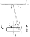
- FIG. 2A is a drawing of the first light beam apparatus 181 in a representative embodiment in accordance with the invention. Since in the representative embodiment, the first light beam apparatus 181 and the second light beam apparatus 182 are substantially identical, only one will be described herein.
- the light beam apparatus 181 comprises a light beam source 210 , which could be for example a light emitting diode (LED) 210 , a surface mount LED 210 , or a laser diode 210 and a light beam lens 240 .
- the light from the light beam source 210 is focused and directed by the light beam lens 240 in the general direction of the optical axis 190 of the image recording system 105 .
- the light beam lens 240 images the light from the light beam source 210 to a dot on the object 140 when the object 140 is in the second position 152 , i.e., when the image 155 of the object 140 is in focus on the image recording medium 130 .
- Figure 2B is a drawing of another first light beam apparatus 181 in a representative embodiment in accordance with the invention. Since in the representative embodiments, the first light beam apparatus 181 and the second light beam apparatus 182 are substantially identical, only one will be describe herein.
- the light beam apparatus 181 comprises the light beam source 210 , which could be for example the light emitting diode (LED) 210 , the surface mount LED 210 , or the laser diode 210 , a diffuser 220 , a light blocking plate 230 , and the light beam lens 240 .
- the light beam source 210 could be for example the light emitting diode (LED) 210 , the surface mount LED 210 , or the laser diode 210 , a diffuser 220 , a light blocking plate 230 , and the light beam lens 240 .
- the diffuser 220 diffuses the light emitted by the light beam source 210 over the area defined by a perimeter 250 of the diffuser 220 with substantially all of the remaining light from the light beam source 210 being blocked by the light blocking plate 230 .
- the light passing through the diffuser 220 is focused by the light beam lens 240 and directed in the general direction of the optical axis 190 of the image recording system 105 .
- the light beam lens 240 images the light passing through the diffuser 220 to a dot on the object 140 when the object 140 is in the second position 152 , i.e., when the image 155 of the object 140 is in focus on the image recording medium 130 .
- Figure 3 is another drawing of the image recording system 105 with a light beam focusing array 310 in accordance with a representative embodiment of the invention.
- the light beam focusing array 310 comprises the first light beam apparatus 181 , the second light beam apparatus 182 , a third light beam apparatus 312 , and a fourth light beam apparatus 314 .
- First and second light beams 183 , 184 from the first light beam apparatus 181 and the second light beam apparatus 182 may or may not be directed toward the optical axis 190 of the image recording system 105 and are incident upon a different area of the object 140 than are third and fourth light beams 322 , 324 from the third light beam apparatus 312 and the fourth light beam apparatus 314 .
- third and fourth light beams 322 , 324 are not shown in figure 3 but are substantially the same as the first light beam 183 shown in figure 2A.
- the light-beam focusing array 310 further comprises a fifth light beam apparatus 316 and a sixth light beam apparatus 318 in addition to the first light beam apparatus 181 , the second light beam apparatus 182 , the third light beam apparatus 312 , and the fourth light beam apparatus 314 .
- fifth and sixth light beams 326 , 328 from the fifth light beam apparatus 316 and the sixth light beam apparatus 318 are not directed toward the optical axis 190 of the image recording system 105 and are incident upon a different area of the object 140 than are first, second, third, and fourth light beams 183 , 184 , 322 , 324 from the first light beam apparatus 181 , the second light beam apparatus 182 , the third light beam apparatus 312 , and the fourth light beam apparatus 314 .
- third, fourth, fifth, and sixth light beam apparatuses 312 , 314 , 316 , 318 are substantially as previously shown and described in figures 2A and 2B for first light beam apparatus 181 .
- Exact placement of light beam apparatuses 181 , 182 , 312 , 314 , 316 , 318 is typically not critical. However, the greater the separation between first and second light beam apparatuses 181 , 182 the more precisely the overlaying of the first and second light beams 183 , 184 can be determined and the more precisely the image 155 can be focused onto the image recording medium 130 . In addition, the greater the separation between third and fourth light beam apparatuses 312 , 314 the more precisely the overlaying of the third and fourth light beams 322 , 324 can be determined and again the more precisely the image 155 can be focused onto the image recording medium 130 .
- a primary advantage of the embodiments as described in the present patent document over prior image recording systems 105 having fixed lens systems 110 is the ability to easily and inexpensively record a focused image.
- the operator can easily locate the object 140 in the fixed focal plane 170 by adjusting the distance between the object 140 and the lens 110 until the appropriate light beam images 185 , 186 incident on the object 140 from the appropriate light beam apparatus 181 , 182 overlap.
- Inexpensive, easy to use image recording systems 105 can be fabricated using the teachings of the present patent document.
- the effect of tilt of the image recording system 105 with respect to the object 140 can be minimized with additional third, fourth, fifth, and sixth light beam apparatuses 312 , 314 , 316 , 318 and additional overlaying of third and fourth light beams 322 , 324 and additional overlaying of fifth and sixth light beams 326 , 328 on the object when the object lies in the focal plane 170 .
Landscapes
- Physics & Mathematics (AREA)
- General Physics & Mathematics (AREA)
- Optics & Photonics (AREA)
- Studio Devices (AREA)
- Automatic Focus Adjustment (AREA)
- Lenses (AREA)
- Focusing (AREA)
- Light Sources And Details Of Projection-Printing Devices (AREA)
Abstract
Description
Claims (10)
- An image recording system [105], comprising:an image recording medium [130];a lens [110] having an optical axis [190] and located at a first distance [120] along the optical axis [190] from the image recording medium [130], wherein the lens [110] projects a substantially focused image [155] of an object [140] onto the image recording medium [130] when the object [140] is located at a second distance [165] from the lens [110] along the optical axis [190];a first light beam apparatus [181] fixed in position relative to the lens [110], wherein the first light beam apparatus [181] has capability of emitting a first light beam [183]; anda second light beam apparatus [182] fixed in position relative to the lens [110], wherein the second light beam apparatus [182] has capability of emitting a second light beam [184] and wherein the first light beam [183] and the second light beam [184] intersect at a distance equal to the value of the second distance [165] from a plane perpendicular to the optical axis [190] and passing through the center of the lens [110].
- The image recording system [105] as recited in claim 1, wherein the first light beam [183] and the second light beam [184] further intersect on the optical axis [190].
- The image recording system [105] as recited in claim 1, wherein the image recording medium [130] is selected from the group consisting of photographic film [130] or an image sensor [130].
- The image recording apparatus [105] as recited in claim 1, wherein first and second light beam apparatus [181,182] each comprise a light beam source [210] and a light beam lens [240].
- The image recording system [105] as recited in claim 4, wherein the light beam source [210] is selected from the group consisting of a light emitting diode (LED) [210], a surface mount LED [210], or a laser diode [210].
- The image recording system [105] as recited in claim 1, wherein the image recording system [105] is selected from the group consisting of a photographic film still camera [105], a photographic film motion picture camera [105], an analog video camera [105], a digital still camera [105], or a digital video camera [105].
- The image recording system [105] as recited in claim 1 further comprising:a third light beam apparatus [312] fixed in position relative to the lens [110], wherein the third light beam apparatus [312] has capability of emitting a third light beam [322]; anda fourth light beam apparatus [314] fixed in position relative to the lens [110], wherein the fourth light beam apparatus [314] has capability of emitting a fourth light beam [324] and wherein the third light beam [322] and the fourth light beam [324] intersect at a distance equal to the value of the second distance [165] from a plane perpendicular to the optical axis [190] and passing through the center of the lens [110].
- The image recording system [105] as recited in claim 7, wherein the image recording system [105] is selected from the group consisting of a photographic film still camera [105], a photographic film motion picture camera [105], an analog video camera [105], a digital still camera [105], or a digital video camera [105].
- The image recording system [105] as recited in claim 7 further comprising:a fifth light beam apparatus [316] fixed in position relative to the lens [110], wherein the fifth light beam apparatus [316] has capability of emitting a fifth light beam [326]; anda sixth light beam apparatus [318] fixed in position relative to the lens [110], wherein the sixth light beam apparatus [318] has capability of emitting a sixth light beam [328] and wherein the fifth light beam [326] and the sixth light beam [328] intersect at a distance equal to the value of the second distance [165] from a plane perpendicular to the optical axis [190] and passing through the center of the lens [110].
- The image recording system [105] as recited in claim 9, wherein the image recording system [105] is selected from the group consisting of a photographic film still camera [105], a photographic film motion picture camera [105], an analog video camera [105], a digital still camera [105], or a digital video camera [105].
Applications Claiming Priority (2)
| Application Number | Priority Date | Filing Date | Title |
|---|---|---|---|
| US420084 | 1999-10-18 | ||
| US09/420,084 US6774945B1 (en) | 1999-10-18 | 1999-10-18 | Focusing apparatus for image recording system |
Publications (3)
| Publication Number | Publication Date |
|---|---|
| EP1094349A2 true EP1094349A2 (en) | 2001-04-25 |
| EP1094349A3 EP1094349A3 (en) | 2003-03-26 |
| EP1094349B1 EP1094349B1 (en) | 2006-02-08 |
Family
ID=23665019
Family Applications (1)
| Application Number | Title | Priority Date | Filing Date |
|---|---|---|---|
| EP00112169A Expired - Lifetime EP1094349B1 (en) | 1999-10-18 | 2000-06-06 | Focusing apparatus for image recording system |
Country Status (5)
| Country | Link |
|---|---|
| US (1) | US6774945B1 (en) |
| EP (1) | EP1094349B1 (en) |
| JP (1) | JP2001166360A (en) |
| DE (1) | DE60025862D1 (en) |
| TW (1) | TW461970B (en) |
Cited By (2)
| Publication number | Priority date | Publication date | Assignee | Title |
|---|---|---|---|---|
| NL1032488C2 (en) * | 2006-09-13 | 2008-03-14 | Alb Van Gool R & D | Device and method for positioning recording means for recording images relative to an object. |
| WO2012011809A1 (en) | 2010-07-21 | 2012-01-26 | Diaderma B.V. | Camera and method for forming a recording of an image of at least a part of an object |
Families Citing this family (9)
| Publication number | Priority date | Publication date | Assignee | Title |
|---|---|---|---|---|
| US6822687B1 (en) * | 1999-07-08 | 2004-11-23 | Pentax Corporation | Three-dimensional image capturing device and its laser emitting device |
| JP2005221731A (en) * | 2004-02-05 | 2005-08-18 | Konica Minolta Photo Imaging Inc | Imaging device |
| US20070188651A1 (en) * | 2006-02-14 | 2007-08-16 | Akihiro Machida | Automatically capturing focused images obtained through unguided manual focus adjustment |
| JP4799216B2 (en) * | 2006-03-03 | 2011-10-26 | 富士通株式会社 | Imaging device having distance measuring function |
| KR100843099B1 (en) * | 2007-01-26 | 2008-07-03 | 삼성전자주식회사 | Apparatus and method for restoring an image |
| FR3022351B1 (en) * | 2014-06-17 | 2017-10-06 | Quantificare | CONTACTLESS DEVICE FOR STANDARDIZING PHOTOGRAPHY |
| CN104104876B (en) * | 2014-07-25 | 2017-09-15 | 广东欧珀移动通信有限公司 | A fast focusing method, device and mobile device |
| US10196005B2 (en) | 2015-01-22 | 2019-02-05 | Mobileye Vision Technologies Ltd. | Method and system of camera focus for advanced driver assistance system (ADAS) |
| TWI692969B (en) * | 2019-01-15 | 2020-05-01 | 沅聖科技股份有限公司 | Camera automatic focusing method and device thereof |
Family Cites Families (15)
| Publication number | Priority date | Publication date | Assignee | Title |
|---|---|---|---|---|
| DE942848C (en) | 1951-08-10 | 1956-05-09 | Andreas Veigel Fa | Device for focusing photographic equipment |
| US3738248A (en) * | 1972-02-18 | 1973-06-12 | Us Navy | Photographic module having acoustic transducer |
| US4032934A (en) | 1974-12-26 | 1977-06-28 | Hendrickson Kenneth L | Automatic focusing system |
| FR2504281A1 (en) | 1981-04-16 | 1982-10-22 | Euromask | PROJECTION APPARATUS WITH FOCUSING DEVICE |
| US4836671A (en) * | 1985-04-08 | 1989-06-06 | Charles Lescrenier | Locating device |
| JPS62229013A (en) * | 1986-03-31 | 1987-10-07 | Toshiba Corp | Image sensing apparatus |
| JPS62229016A (en) | 1986-03-31 | 1987-10-07 | Toshiba Corp | Pattern inspecting device |
| US4777501A (en) | 1987-04-20 | 1988-10-11 | Harbor Branch Oceanographic Institution, Inc. | Underwater optical methods and apparatus |
| US4914460A (en) | 1987-05-29 | 1990-04-03 | Harbor Branch Oceanographic Institution Inc. | Apparatus and methods of determining distance and orientation |
| US5550641A (en) * | 1991-05-15 | 1996-08-27 | Gentech Corporation | System and method for rendering images |
| US5142299A (en) | 1991-10-15 | 1992-08-25 | Braun Photo-Aquatic Systems | Hand held system for close-range underwater photography composing and focusing |
| US5289220A (en) * | 1992-12-28 | 1994-02-22 | Polaroid Corporation | Detachable close-up lens assembly for an adjustable focus lens camera incorporating a photoranging system |
| US5459532A (en) * | 1993-03-29 | 1995-10-17 | Seiko Epson Corporation | Automatic focus adjuster for projection display systems having focus adjustment display symbols |
| US5416544A (en) | 1993-12-07 | 1995-05-16 | Stapleton; Michael E. | Camera lens attachment to aid focusing |
| JPH11288063A (en) | 1998-04-03 | 1999-10-19 | Konica Corp | Film unit equipped with lens |
-
1999
- 1999-10-18 US US09/420,084 patent/US6774945B1/en not_active Expired - Fee Related
-
2000
- 2000-05-18 TW TW089109551A patent/TW461970B/en not_active IP Right Cessation
- 2000-06-06 EP EP00112169A patent/EP1094349B1/en not_active Expired - Lifetime
- 2000-06-06 DE DE60025862T patent/DE60025862D1/en not_active Expired - Lifetime
- 2000-10-18 JP JP2000317531A patent/JP2001166360A/en active Pending
Cited By (3)
| Publication number | Priority date | Publication date | Assignee | Title |
|---|---|---|---|---|
| NL1032488C2 (en) * | 2006-09-13 | 2008-03-14 | Alb Van Gool R & D | Device and method for positioning recording means for recording images relative to an object. |
| WO2008033010A1 (en) * | 2006-09-13 | 2008-03-20 | Alb. Van Gool R & D | Device and method for positioning recording means for recording images relative to an object |
| WO2012011809A1 (en) | 2010-07-21 | 2012-01-26 | Diaderma B.V. | Camera and method for forming a recording of an image of at least a part of an object |
Also Published As
| Publication number | Publication date |
|---|---|
| EP1094349B1 (en) | 2006-02-08 |
| JP2001166360A (en) | 2001-06-22 |
| EP1094349A3 (en) | 2003-03-26 |
| US6774945B1 (en) | 2004-08-10 |
| DE60025862D1 (en) | 2006-04-20 |
| TW461970B (en) | 2001-11-01 |
Similar Documents
| Publication | Publication Date | Title |
|---|---|---|
| US7405762B2 (en) | Camera having AF function | |
| US4878080A (en) | Camera zoom lens automatic magnification apparatus | |
| US4067026A (en) | Front projection system embodying a single lens | |
| US4582411A (en) | Automatic focusing apparatus | |
| US6774945B1 (en) | Focusing apparatus for image recording system | |
| US4801963A (en) | Focus detecting system | |
| US5589908A (en) | Control for variable magnification in an imaging apparatus | |
| JPH04295837A (en) | Active ranging device with remote control function | |
| US5530512A (en) | Autofocus camera | |
| GB2352919A (en) | Imaging device for selecting most in focus image from plural stored images. | |
| JPS60233610A (en) | distance measuring device | |
| EP0950912A2 (en) | Image forming apparatus with intermediate image surface | |
| US20050041133A1 (en) | Video-camera unit and adapter for a video-camera unit | |
| US20020186971A1 (en) | AF auxiliary light projector for AF camera | |
| US4428653A (en) | Mirror reflex camera with an electronic range finder | |
| JP2003215441A (en) | Camera | |
| USRE32959E (en) | Automatic focusing apparatus | |
| JP3063240B2 (en) | Converter device and camera system using the same | |
| US5379082A (en) | Method of automatically focusing glass-mounted and glassless slides in slide projectors | |
| JPS63139310A (en) | Pattern projecting device for detecting focus | |
| JP2579977Y2 (en) | Auxiliary floodlight for distance measurement | |
| JP2006184321A (en) | FOCUS DETECTION DEVICE AND OPTICAL DEVICE HAVING FOCUS DETECTION DEVICE | |
| JP3272636B2 (en) | Camera viewfinder device | |
| JPS6252538A (en) | Automatic focusing camera | |
| JPH06167652A (en) | Focus detecting device and automatic focus type photographing device |
Legal Events
| Date | Code | Title | Description |
|---|---|---|---|
| PUAI | Public reference made under article 153(3) epc to a published international application that has entered the european phase |
Free format text: ORIGINAL CODE: 0009012 |
|
| AK | Designated contracting states |
Kind code of ref document: A2 Designated state(s): AT BE CH CY DE DK ES FI FR GB GR IE IT LI LU MC NL PT SE |
|
| AX | Request for extension of the european patent |
Free format text: AL;LT;LV;MK;RO;SI |
|
| PUAL | Search report despatched |
Free format text: ORIGINAL CODE: 0009013 |
|
| AK | Designated contracting states |
Kind code of ref document: A3 Designated state(s): AT BE CH CY DE DK ES FI FR GB GR IE IT LI LU MC NL PT SE |
|
| AX | Request for extension of the european patent |
Extension state: AL LT LV MK RO SI |
|
| RIC1 | Information provided on ipc code assigned before grant |
Ipc: 7G 03B 13/32 B Ipc: 7G 02B 7/28 B Ipc: 7G 02B 7/04 A Ipc: 7G 02B 27/40 B |
|
| 17P | Request for examination filed |
Effective date: 20030430 |
|
| AKX | Designation fees paid |
Designated state(s): DE FR GB |
|
| 17Q | First examination report despatched |
Effective date: 20040318 |
|
| GRAP | Despatch of communication of intention to grant a patent |
Free format text: ORIGINAL CODE: EPIDOSNIGR1 |
|
| GRAS | Grant fee paid |
Free format text: ORIGINAL CODE: EPIDOSNIGR3 |
|
| GRAA | (expected) grant |
Free format text: ORIGINAL CODE: 0009210 |
|
| AK | Designated contracting states |
Kind code of ref document: B1 Designated state(s): DE FR GB |
|
| REG | Reference to a national code |
Ref country code: GB Ref legal event code: FG4D |
|
| REF | Corresponds to: |
Ref document number: 60025862 Country of ref document: DE Date of ref document: 20060420 Kind code of ref document: P |
|
| PG25 | Lapsed in a contracting state [announced via postgrant information from national office to epo] |
Ref country code: DE Free format text: LAPSE BECAUSE OF FAILURE TO SUBMIT A TRANSLATION OF THE DESCRIPTION OR TO PAY THE FEE WITHIN THE PRESCRIBED TIME-LIMIT Effective date: 20060509 |
|
| PGFP | Annual fee paid to national office [announced via postgrant information from national office to epo] |
Ref country code: FR Payment date: 20060620 Year of fee payment: 7 |
|
| PGFP | Annual fee paid to national office [announced via postgrant information from national office to epo] |
Ref country code: DE Payment date: 20060731 Year of fee payment: 7 |
|
| PLBE | No opposition filed within time limit |
Free format text: ORIGINAL CODE: 0009261 |
|
| STAA | Information on the status of an ep patent application or granted ep patent |
Free format text: STATUS: NO OPPOSITION FILED WITHIN TIME LIMIT |
|
| 26N | No opposition filed |
Effective date: 20061109 |
|
| EN | Fr: translation not filed | ||
| PGFP | Annual fee paid to national office [announced via postgrant information from national office to epo] |
Ref country code: GB Payment date: 20070628 Year of fee payment: 8 |
|
| PG25 | Lapsed in a contracting state [announced via postgrant information from national office to epo] |
Ref country code: FR Free format text: LAPSE BECAUSE OF FAILURE TO SUBMIT A TRANSLATION OF THE DESCRIPTION OR TO PAY THE FEE WITHIN THE PRESCRIBED TIME-LIMIT Effective date: 20070330 |
|
| GBPC | Gb: european patent ceased through non-payment of renewal fee |
Effective date: 20080606 |
|
| PG25 | Lapsed in a contracting state [announced via postgrant information from national office to epo] |
Ref country code: GB Free format text: LAPSE BECAUSE OF NON-PAYMENT OF DUE FEES Effective date: 20080606 |