EP1094343A2 - Optical mirror, optical scanner and laser machining apparatus using the same - Google Patents
Optical mirror, optical scanner and laser machining apparatus using the same Download PDFInfo
- Publication number
- EP1094343A2 EP1094343A2 EP00122895A EP00122895A EP1094343A2 EP 1094343 A2 EP1094343 A2 EP 1094343A2 EP 00122895 A EP00122895 A EP 00122895A EP 00122895 A EP00122895 A EP 00122895A EP 1094343 A2 EP1094343 A2 EP 1094343A2
- Authority
- EP
- European Patent Office
- Prior art keywords
- mirror
- reflecting surface
- optical mirror
- optical
- holder
- Prior art date
- Legal status (The legal status is an assumption and is not a legal conclusion. Google has not performed a legal analysis and makes no representation as to the accuracy of the status listed.)
- Granted
Links
Images





Classifications
-
- B—PERFORMING OPERATIONS; TRANSPORTING
- B23—MACHINE TOOLS; METAL-WORKING NOT OTHERWISE PROVIDED FOR
- B23K—SOLDERING OR UNSOLDERING; WELDING; CLADDING OR PLATING BY SOLDERING OR WELDING; CUTTING BY APPLYING HEAT LOCALLY, e.g. FLAME CUTTING; WORKING BY LASER BEAM
- B23K26/00—Working by laser beam, e.g. welding, cutting or boring
- B23K26/08—Devices involving relative movement between laser beam and workpiece
-
- B—PERFORMING OPERATIONS; TRANSPORTING
- B23—MACHINE TOOLS; METAL-WORKING NOT OTHERWISE PROVIDED FOR
- B23K—SOLDERING OR UNSOLDERING; WELDING; CLADDING OR PLATING BY SOLDERING OR WELDING; CUTTING BY APPLYING HEAT LOCALLY, e.g. FLAME CUTTING; WORKING BY LASER BEAM
- B23K26/00—Working by laser beam, e.g. welding, cutting or boring
- B23K26/08—Devices involving relative movement between laser beam and workpiece
- B23K26/082—Scanning systems, i.e. devices involving movement of the laser beam relative to the laser head
-
- G—PHYSICS
- G02—OPTICS
- G02B—OPTICAL ELEMENTS, SYSTEMS OR APPARATUS
- G02B26/00—Optical devices or arrangements for the control of light using movable or deformable optical elements
- G02B26/08—Optical devices or arrangements for the control of light using movable or deformable optical elements for controlling the direction of light
- G02B26/10—Scanning systems
- G02B26/101—Scanning systems with both horizontal and vertical deflecting means, e.g. raster or XY scanners
-
- G—PHYSICS
- G02—OPTICS
- G02B—OPTICAL ELEMENTS, SYSTEMS OR APPARATUS
- G02B7/00—Mountings, adjusting means, or light-tight connections, for optical elements
- G02B7/18—Mountings, adjusting means, or light-tight connections, for optical elements for prisms; for mirrors
- G02B7/182—Mountings, adjusting means, or light-tight connections, for optical elements for prisms; for mirrors for mirrors
- G02B7/1821—Mountings, adjusting means, or light-tight connections, for optical elements for prisms; for mirrors for mirrors for rotating or oscillating mirrors
Definitions
- the present invention relates to an optical mirror rotatable rapidly, and an optical scanner and a laser machining apparatus employing the improved mirror.
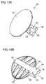
- Optical mirror 120 (Figs. 12A, 12B) is attached directly to the rotary shaft of the motor (not shown), and used for a galvanometer scanner in which the rotation angle of the motor defines a reflecting direction of light.
- the motor shaft is fitted in semi-circular groove 122 and held with a retaining ring (not shown) having also a semi-circular groove, then secured by screws at screw holes 123.
- Diameters both of groove 122 and the groove of the retaining ring are generally sized to be a few micrometers bigger than that of the motor shaft.
- the perimeter of the motor shaft measures bigger than the perimeter of roughly semi-cylindrical shape formed from facing each semi-circular portion of groove 122 and the retaining ring's groove. Therefore, fastening the screws to secure the optical mirror to the motor shaft inconveniently applies a stress to screw holes 123 vertically with reflecting surface 121.
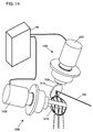
- Optical mirror 141A of galvano-mirror 140A horizontally rotates about motor shaft 142A, while mirror 141B of galvano-mirror 140B vertically rotates about motor shaft 142B.
- the optical mirror of the present invention comprises a reflecting surface having optical characteristics, a holder to attach the mirror to other member, and a plurality of ribs disposed on the rear of the reflecting surface.
- the mirror also has slits in the ribs peripherally disposed close to the holder.
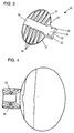
- Optical mirror 30 shown in Fig. 3 differs from optical mirror 10 shown in Fig. 1 in that ribs 16 are removed from its constitution.
- Mirror support beam 34 functions as an absorber of the vibrations created in the axial direction of the motor shaft while the motor is rotating. Besides, ribs 35 make a large contribute to minimize the fluttering of the mirror when rotating.
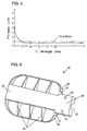
- Fig. 5 shows the relation between the distortion in the mirror surface and slit length "L" in the ribs disposed near the holder.
- the distortion in the reflecting surface shown in Fig. 5 is measured, with the motor shaft attached to the optical mirror.
- the optical mirror made of a material containing beryllium is employed for the measurement.
- the acceptable distortion is at most 900 nm. It is equivalent to the optical path difference of at most one and a half wavelengths, when the light having its beam diameter greater than 25 mm is reflected and measured by an interferometer employing helium neon laser.
- the optical mirror shown in Fig. 6 is also effective. Also like the structure shown in Fig. 3, ribs 66 disposed close to the holder may be removed from the constitution.
- Reflecting surface 71 as shown in Fig.7, has on its rear surface:
- Mirror support beam 74 functions as an absorber of the vibrations created in the axial direction of the motor shaft while the motor is rotating. Besides, ribs 75 make a large contribute to minimize the fluttering of the mirror when rotating.
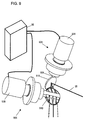
- the two-dimensional optical scanner of the embodiment comprises, as shown in Fig. 9, two sets of galvano-mirrors 90A, 90B and position control unit 98.
- the optical mirror described in the first or the second preferred embodiment is used for optical mirror 91A and 91B for galvano-mirrors 90A and 90B.
- Optical mirror 91A reflects laser beam 95 shown in Fig. 9 to direct an intended position on optical mirror 91B.
- the position sensor which is built in motor 93A of galvano-mirror 90A, detects the orientation of mirror 91A. Getting the signal back from the position sensor, position control unit 98 adjusts the reflecting direction.
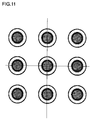
- Fig. 11 shows the strength distribution of laser spots, comparing with each other the strength at nine spots in the entire scan area. At all the spots in the center and the periphery; as shown in Fig. 11, each main beam for machining maintains its diameter's shape being circular, i.e. symmetric. In machining a workpiece made of resin with relatively low work threshold, each main beam can evenly machines each hole with its diameter's shape being circular, or symmetric. Unlike the machining with the conventional apparatus, machined workpieces have no flaws such as unwanted holes near the main machined hole.
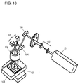
- the reflecting surface of the optical mirror for the laser machining apparatus of the embodiment is roughly circular shaped, it is possible to employ a roughly rectangular shaped surface for the optical mirror, as shown in Fig. 6, for the same effect. As shown in Fig. 10, combination of these different shaped mirrors is also available: one optical mirror may have a roughly circular mirror, while the other may have a roughly rectangular one.
- the ribs close to the holder have slits adjacent to the support beam running across the rear side of the reflecting surface.
- the holder for the optical mirror is structured such that the motor shaft-to-be-attached surface of the holder is arranged almost vertically with the reflecting surface. With such improved structure, the distortion, which is occurred in the reflecting surface due to fastening screws, is locally and negligible.
- the reflecting mirror of the present invention allows the workpiece to be free from flaws outside its main machined hole.
Landscapes
- Physics & Mathematics (AREA)
- Optics & Photonics (AREA)
- Engineering & Computer Science (AREA)
- Plasma & Fusion (AREA)
- Mechanical Engineering (AREA)
- General Physics & Mathematics (AREA)
- Optical Elements Other Than Lenses (AREA)
- Laser Beam Processing (AREA)
- Mechanical Optical Scanning Systems (AREA)
- Mounting And Adjusting Of Optical Elements (AREA)
Abstract
Description
Claims (10)
- A rotatable optical mirror attached to a motor shaft, comprising:a reflecting surface; anda holder by which said optical mirror is attached to the motor shaft,said reflecting surface further includes on its rear surface a support beam which is centered across the rear surface and extended from said holder, and plural first ribs extending from said support beam toward a rim of said reflecting surface.
- The optical mirror as defined in claim 1, wherein peripheral second ribs, other than said first ribs, are disposed along a periphery of the rear surface of said reflecting surface, with a space kept from said support beam.
- The optical mirror as defined in claim 2, wherein said second ribs are disposed along a periphery of the rear surface of said reflecting surface, spaced at least 1 mm from said support beam.
- A rotatable optical mirror attached to a motor shaft, comprising:a reflecting surface; anda holder by which said optical mirror is attached to the motor shaft,said reflecting surface further includes on its rear surface a support beam which is centered across the surface and extended from said holder, and plural first ribs extending from said support beam, wherein a motor shaft-to-be-attached surface of said holder is arranged almost vertically with said reflecting surface.
- An optical scanner having a motor with a motor shaft and an optical mirror, said optical mirror comprising:a reflecting surface; anda holder by which said optical mirror is attached to the motor shaft,said reflecting surface further includes on its rear surface a support beam which is centered across the surface and extended from said holder, and plural first ribs extending from said support beam toward a rim of the rear surface of said reflecting surface.
- The optical scanner as defined in claim 4, wherein said optical mirror for said scanner includes on its rear surface, other than said plural first ribs, peripheral second ribs disposed along the periphery of the rear surface of said reflecting surface, with a space kept from said support beam.
- An optical scanner having a motor with a motor shaft and an optical mirror, said optical mirror comprising:a reflecting surface; anda holder by which said optical mirror is attached to the motor shaft,said reflecting surface further includes on its rear surface a support beam which is centered across the surface and extended from said holder, and plural ribs extending from said support beam,said optical mirror wherein a motor shaft-to-be-attached surface of said holder is arranged almost vertically with said reflecting surface.
- A laser machining apparatus equipped with a laser oscillator and an optical scanner arranged on an optical path of a laser beam from the laser oscillator, said optical scanner comprising:a motor having a motor shaft; andan optical mirror,said optical mirror further comprising:a reflecting surface; anda holder by which said optical mirror is attached to the motor shaft,said reflecting surface further includes on its rear surface a support beam which is centered across the surface and extended from said holder, and plural first ribs extending from said support beam toward a rim of the rear surface of said reflecting surface.
- The laser machining apparatus as defined in claim 8, wherein said optical mirror for said scanner includes on its rear surface, other than said plural first ribs, peripheral second ribs disposed along the periphery of the rear surface of said reflecting surface, with a space kept from said support beam.
- A laser machining apparatus equipped with a laser oscillator and an optical scanner arranged on an optical path of a laser beam from the laser oscillator, said optical scanner comprising:a motor having a motor shaft; andan optical mirror,said optical mirror further comprising:a reflecting surface; anda holder by which said optical mirror is attached to the motor shaft,said reflecting surface includes on its rear surface a support beam which is centered across the surface and extended from said holder, and plural ribs extending from said support beam toward a rim of said reflecting surface, wherein a motor shaft-to-be-attached surface of said holder is arranged almost vertically with said reflecting surface.
Applications Claiming Priority (2)
| Application Number | Priority Date | Filing Date | Title |
|---|---|---|---|
| JP29963399A JP3531554B2 (en) | 1999-10-21 | 1999-10-21 | Optical mirror, optical scanner and laser processing machine |
| JP29963399 | 1999-10-21 |
Publications (3)
| Publication Number | Publication Date |
|---|---|
| EP1094343A2 true EP1094343A2 (en) | 2001-04-25 |
| EP1094343A3 EP1094343A3 (en) | 2003-05-21 |
| EP1094343B1 EP1094343B1 (en) | 2004-12-29 |
Family
ID=17875129
Family Applications (1)
| Application Number | Title | Priority Date | Filing Date |
|---|---|---|---|
| EP00122895A Expired - Lifetime EP1094343B1 (en) | 1999-10-21 | 2000-10-20 | Optical mirror, optical scanner and laser machining apparatus using the same |
Country Status (6)
| Country | Link |
|---|---|
| US (2) | US6556331B1 (en) |
| EP (1) | EP1094343B1 (en) |
| JP (1) | JP3531554B2 (en) |
| KR (1) | KR100678809B1 (en) |
| DE (1) | DE60017051T2 (en) |
| TW (1) | TW460353B (en) |
Cited By (3)
| Publication number | Priority date | Publication date | Assignee | Title |
|---|---|---|---|---|
| DE102006056406B4 (en) * | 2006-06-07 | 2010-07-22 | Mitsubishi Electric Corporation | laser oscillating |
| DE102017128356A1 (en) | 2017-11-30 | 2019-06-06 | Trumpf Laser Gmbh | Scan mirror, mirror holder and scanning mirror unit for a laser scanning system |
| DE102018205786A1 (en) | 2018-04-17 | 2019-10-17 | Trumpf Laser Gmbh | Scanner mirror, scanner device and irradiation device |
Families Citing this family (17)
| Publication number | Priority date | Publication date | Assignee | Title |
|---|---|---|---|---|
| US7453617B2 (en) * | 2004-08-18 | 2008-11-18 | Lg Electronics Inc. | Scanning device and fabrication method thereof |
| JP4522315B2 (en) * | 2005-04-28 | 2010-08-11 | 三菱電機株式会社 | Scan mirror, method for manufacturing the same, and laser processing machine |
| US8057463B2 (en) * | 2006-04-07 | 2011-11-15 | Amo Development, Llc. | Adaptive pattern correction for laser scanners |
| CN101754832B (en) | 2007-06-12 | 2014-03-26 | 技术线有限责任公司 | High speed and high power laser scribing methods and systems |
| USD642265S1 (en) * | 2007-07-26 | 2011-07-26 | Optosic Gmbh | Pair of galvano scanning mirrors |
| JP4974855B2 (en) * | 2007-11-09 | 2012-07-11 | 三菱電機株式会社 | Optical mirror for laser light |
| US8081362B2 (en) * | 2009-08-12 | 2011-12-20 | Mitsubishi Electric Research Laboratories, Inc. | Method and apparatus for stabilizing galvanometer scanner |
| JP5700793B2 (en) * | 2011-01-20 | 2015-04-15 | 株式会社キーエンス | Laser processing equipment |
| US8585226B2 (en) * | 2011-07-29 | 2013-11-19 | Cambridge Technology, Inc. | Systems and methods for balancing mirrors in limited rotation motor systems |
| EP2737357A4 (en) | 2011-07-29 | 2015-04-22 | Cambridge Technology Inc | SYSTEMS AND METHODS FOR PROVIDING MIRRORS WITH HIGH RIGIDITY AND LOW INERTIA INVOLVING CHEMICAL ENGRAVING |
| JP5868226B2 (en) * | 2012-03-12 | 2016-02-24 | 住友重機械工業株式会社 | Galvano scanner |
| KR102435765B1 (en) * | 2015-09-14 | 2022-08-24 | 삼성디스플레이 주식회사 | Laser crystalling apparatus |
| WO2018189828A1 (en) | 2017-04-12 | 2018-10-18 | 三菱電機株式会社 | Galvanomirror, galvanoscanner using galvanomirror, laser processing machine using galvanomirror, and method for manufacturing galvanomirror |
| CN112269261A (en) * | 2020-09-30 | 2021-01-26 | 广州新可激光设备有限公司 | Manufacturing process of high-speed reciprocating rotary galvanometer |
| WO2022112418A1 (en) * | 2020-11-26 | 2022-06-02 | Zoller & Fröhlich GmbH | Laser scanner |
| JP7273780B2 (en) | 2020-12-09 | 2023-05-15 | 矢崎総業株式会社 | head-up display device |
| DE102022130481A1 (en) * | 2022-11-17 | 2024-05-23 | Scanlab Gmbh | Scanning mirror unit for a laser scanning device |
Family Cites Families (9)
| Publication number | Priority date | Publication date | Assignee | Title |
|---|---|---|---|---|
| DE2527731A1 (en) * | 1975-06-21 | 1976-12-23 | Eltro Gmbh | Oscillating mirror in optical system - has oscillation and resonance system and is operated by driving shaft which is supported on both sides |
| US4655543A (en) * | 1985-05-08 | 1987-04-07 | General Scanning, Inc. | Mount for attaching an optical element to a rotating shaft |
| US4820911A (en) * | 1986-07-11 | 1989-04-11 | Photographic Sciences Corporation | Apparatus for scanning and reading bar codes |
| DE3625642A1 (en) * | 1986-07-29 | 1988-02-11 | Messerschmitt Boelkow Blohm | TWO STORED TURNTABLE MIRROR FOR OPTICAL SYSTEMS |
| JP2697203B2 (en) * | 1989-11-24 | 1998-01-14 | 三菱電機株式会社 | Reflector |
| US5091646A (en) * | 1990-05-29 | 1992-02-25 | Kollmorgen Corporation | Integrated thermal imaging system |
| JP3164702B2 (en) | 1993-07-27 | 2001-05-08 | シャープ株式会社 | Liquid crystal display |
| JPH07287184A (en) * | 1994-04-19 | 1995-10-31 | Fuji Photo Film Co Ltd | Resonance type optical deflector |
| US6239928B1 (en) * | 1999-09-20 | 2001-05-29 | Donnelly Corporation | Extendable exterior rearview mirror assembly for vehicles |
-
1999
- 1999-10-21 JP JP29963399A patent/JP3531554B2/en not_active Expired - Fee Related
-
2000
- 2000-10-18 KR KR1020000061241A patent/KR100678809B1/en not_active Expired - Fee Related
- 2000-10-19 US US09/691,250 patent/US6556331B1/en not_active Expired - Lifetime
- 2000-10-20 DE DE60017051T patent/DE60017051T2/en not_active Expired - Lifetime
- 2000-10-20 EP EP00122895A patent/EP1094343B1/en not_active Expired - Lifetime
- 2000-10-20 TW TW089122139A patent/TW460353B/en not_active IP Right Cessation
-
2002
- 2002-08-30 US US10/231,204 patent/US6633422B2/en not_active Expired - Lifetime
Cited By (3)
| Publication number | Priority date | Publication date | Assignee | Title |
|---|---|---|---|---|
| DE102006056406B4 (en) * | 2006-06-07 | 2010-07-22 | Mitsubishi Electric Corporation | laser oscillating |
| DE102017128356A1 (en) | 2017-11-30 | 2019-06-06 | Trumpf Laser Gmbh | Scan mirror, mirror holder and scanning mirror unit for a laser scanning system |
| DE102018205786A1 (en) | 2018-04-17 | 2019-10-17 | Trumpf Laser Gmbh | Scanner mirror, scanner device and irradiation device |
Also Published As
| Publication number | Publication date |
|---|---|
| EP1094343A3 (en) | 2003-05-21 |
| EP1094343B1 (en) | 2004-12-29 |
| US20020196512A1 (en) | 2002-12-26 |
| DE60017051D1 (en) | 2005-02-03 |
| US6556331B1 (en) | 2003-04-29 |
| KR20010040117A (en) | 2001-05-15 |
| TW460353B (en) | 2001-10-21 |
| DE60017051T2 (en) | 2005-05-25 |
| KR100678809B1 (en) | 2007-02-05 |
| JP2001116911A (en) | 2001-04-27 |
| US6633422B2 (en) | 2003-10-14 |
| JP3531554B2 (en) | 2004-05-31 |
Similar Documents
| Publication | Publication Date | Title |
|---|---|---|
| EP1094343B1 (en) | Optical mirror, optical scanner and laser machining apparatus using the same | |
| US6285390B1 (en) | Rotatable mirror assembly | |
| GB2307305A (en) | An optical scanning device having a spherical exit window | |
| CA2029767A1 (en) | Laser scanning system for use in laser imaging | |
| US4657360A (en) | Optical system for making an annular beam | |
| KR100228975B1 (en) | A device and a method for correcting astigmatism, bow distortion and field curvature | |
| JPH03179420A (en) | Optical apparatus | |
| JP2001021822A (en) | Optical scanning optical system and image forming apparatus using the same | |
| JP3707508B2 (en) | Optical scanning device | |
| US5555122A (en) | Light scanning device | |
| JPH0915521A (en) | Laser light source device | |
| JPS5815768B2 (en) | Sousakou Gakkei | |
| US5982527A (en) | Inertial stabilization of rotational optical scanners | |
| JPS63316819A (en) | Light beam scanning device | |
| JP2743561B2 (en) | Mirror for laser beam scanner | |
| JP3515641B2 (en) | Laser beam scanning device | |
| JPH10197823A (en) | Scan lens | |
| JP2907292B2 (en) | Achromatic laser scanning optics | |
| JP3922382B2 (en) | Optical scanning device | |
| US5771063A (en) | Method and apparatus for positioning a polygon on a spindle of a laser writer | |
| JP2712034B2 (en) | Scanning optical device | |
| JP3446267B2 (en) | Scanning position adjustment method for optical scanning device | |
| JPS62184433A (en) | Method for correcting unevenness of scanning line in optical scanner and optical scanner | |
| JP4551529B2 (en) | Optical scanning optical device | |
| JPH1138344A (en) | Scanning optical device |
Legal Events
| Date | Code | Title | Description |
|---|---|---|---|
| PUAI | Public reference made under article 153(3) epc to a published international application that has entered the european phase |
Free format text: ORIGINAL CODE: 0009012 |
|
| AK | Designated contracting states |
Kind code of ref document: A2 Designated state(s): AT BE CH CY DE DK ES FI FR GB GR IE IT LI LU MC NL PT SE |
|
| AX | Request for extension of the european patent |
Free format text: AL;LT;LV;MK;RO;SI |
|
| PUAL | Search report despatched |
Free format text: ORIGINAL CODE: 0009013 |
|
| AK | Designated contracting states |
Designated state(s): AT BE CH CY DE DK ES FI FR GB GR IE IT LI LU MC NL PT SE |
|
| AX | Request for extension of the european patent |
Extension state: AL LT LV MK RO SI |
|
| RIC1 | Information provided on ipc code assigned before grant |
Ipc: 7G 02B 7/182 A Ipc: 7G 02B 5/08 B |
|
| 17P | Request for examination filed |
Effective date: 20030604 |
|
| 17Q | First examination report despatched |
Effective date: 20030722 |
|
| AKX | Designation fees paid |
Designated state(s): DE FI SE |
|
| GRAP | Despatch of communication of intention to grant a patent |
Free format text: ORIGINAL CODE: EPIDOSNIGR1 |
|
| GRAS | Grant fee paid |
Free format text: ORIGINAL CODE: EPIDOSNIGR3 |
|
| GRAA | (expected) grant |
Free format text: ORIGINAL CODE: 0009210 |
|
| AK | Designated contracting states |
Kind code of ref document: B1 Designated state(s): DE FI SE |
|
| REG | Reference to a national code |
Ref country code: IE Ref legal event code: FG4D |
|
| REF | Corresponds to: |
Ref document number: 60017051 Country of ref document: DE Date of ref document: 20050203 Kind code of ref document: P |
|
| PLBE | No opposition filed within time limit |
Free format text: ORIGINAL CODE: 0009261 |
|
| STAA | Information on the status of an ep patent application or granted ep patent |
Free format text: STATUS: NO OPPOSITION FILED WITHIN TIME LIMIT |
|
| 26N | No opposition filed |
Effective date: 20050930 |
|
| PGFP | Annual fee paid to national office [announced via postgrant information from national office to epo] |
Ref country code: FI Payment date: 20161010 Year of fee payment: 17 |
|
| PGFP | Annual fee paid to national office [announced via postgrant information from national office to epo] |
Ref country code: DE Payment date: 20171018 Year of fee payment: 18 |
|
| PGFP | Annual fee paid to national office [announced via postgrant information from national office to epo] |
Ref country code: SE Payment date: 20171011 Year of fee payment: 18 |
|
| PG25 | Lapsed in a contracting state [announced via postgrant information from national office to epo] |
Ref country code: FI Free format text: LAPSE BECAUSE OF NON-PAYMENT OF DUE FEES Effective date: 20171020 |
|
| REG | Reference to a national code |
Ref country code: DE Ref legal event code: R119 Ref document number: 60017051 Country of ref document: DE |
|
| REG | Reference to a national code |
Ref country code: SE Ref legal event code: EUG |
|
| PG25 | Lapsed in a contracting state [announced via postgrant information from national office to epo] |
Ref country code: SE Free format text: LAPSE BECAUSE OF NON-PAYMENT OF DUE FEES Effective date: 20181021 Ref country code: DE Free format text: LAPSE BECAUSE OF NON-PAYMENT OF DUE FEES Effective date: 20190501 |