EP1094267A1 - Device for reducing structural noise in pipelines - Google Patents
Device for reducing structural noise in pipelines Download PDFInfo
- Publication number
- EP1094267A1 EP1094267A1 EP99121112A EP99121112A EP1094267A1 EP 1094267 A1 EP1094267 A1 EP 1094267A1 EP 99121112 A EP99121112 A EP 99121112A EP 99121112 A EP99121112 A EP 99121112A EP 1094267 A1 EP1094267 A1 EP 1094267A1
- Authority
- EP
- European Patent Office
- Prior art keywords
- arrangement
- intermediate medium
- particular according
- line
- connection ends
- Prior art date
- Legal status (The legal status is an assumption and is not a legal conclusion. Google has not performed a legal analysis and makes no representation as to the accuracy of the status listed.)
- Withdrawn
Links
Images


Classifications
-
- F—MECHANICAL ENGINEERING; LIGHTING; HEATING; WEAPONS; BLASTING
- F16—ENGINEERING ELEMENTS AND UNITS; GENERAL MEASURES FOR PRODUCING AND MAINTAINING EFFECTIVE FUNCTIONING OF MACHINES OR INSTALLATIONS; THERMAL INSULATION IN GENERAL
- F16L—PIPES; JOINTS OR FITTINGS FOR PIPES; SUPPORTS FOR PIPES, CABLES OR PROTECTIVE TUBING; MEANS FOR THERMAL INSULATION IN GENERAL
- F16L55/00—Devices or appurtenances for use in, or in connection with, pipes or pipe systems
- F16L55/02—Energy absorbers; Noise absorbers
- F16L55/033—Noise absorbers
- F16L55/0337—Noise absorbers by means of a flexible connection
-
- F—MECHANICAL ENGINEERING; LIGHTING; HEATING; WEAPONS; BLASTING
- F16—ENGINEERING ELEMENTS AND UNITS; GENERAL MEASURES FOR PRODUCING AND MAINTAINING EFFECTIVE FUNCTIONING OF MACHINES OR INSTALLATIONS; THERMAL INSULATION IN GENERAL
- F16L—PIPES; JOINTS OR FITTINGS FOR PIPES; SUPPORTS FOR PIPES, CABLES OR PROTECTIVE TUBING; MEANS FOR THERMAL INSULATION IN GENERAL
- F16L27/00—Adjustable joints, Joints allowing movement
- F16L27/10—Adjustable joints, Joints allowing movement comprising a flexible connection only, e.g. for damping vibrations
- F16L27/1021—Adjustable joints, Joints allowing movement comprising a flexible connection only, e.g. for damping vibrations comprising an intermediate resilient element, e.g. a ring
Definitions
- the present invention relates to an arrangement for reduction of structure-borne noise in a fluid medium Pipe and in particular a device for reduction structure-borne noise transmission in hydraulic systems or hydraulic lines at high pressures.
- this problem should be based on be described by hydraulic systems. Because of the non-uniform Flow rate, for example of positive displacement pumps in hydraulic systems and the resulting pressure pulsations become the walls of a hydraulic system Vibrations stimulated. This leads to an emission of Airborne sound and thus to a noise impairment the environment. In hydraulic systems, for example Pipe walls due to the pulsation of the liquid flow stimulated to vibrate. Furthermore, vibrations, that arise in the hydraulic pump itself. Around the sound radiation in downstream systems, e.g. in a hydraulic cylinder or generally at a consumer or avoiding the connecting pipelines is therefore the Smooth flow flow pulsation.
- a pulsation reducer can be used as an expansion hose or is designed as a storage element.
- Such pulsation reducers, such as expansion hoses are from EP 426 789 or EP 471 044.
- Adaptive passive and active Pulsation dampers with a memory element are from EP 679 832 or EP 633 400 known.
- the installation location should be as possible close to the pulsation source (hydraulic pump). Success with this measure a smoothing of the liquid pulsation, so the walls in downstream systems are no longer closed Vibrations stimulated. The vibrations in the pipeline or arise in the hydraulic pump, but are via the pulsation reducer transferred if this is not sufficient Insulation of structure-borne noise guaranteed.
- the object of the present invention is to create an arrangement for reducing vibration or structure-borne sound wave transmission lines carrying fluids, which is particularly suitable in hydraulic systems with high Operating or working pressures.
- a separation area in a line carrying a fluid medium is provided, which is the line carrying the fluid medium interrupts, comprising a connection arrangement for connection of the two corresponding connection ends of the separate Management.
- This separation area consists of at least one intermediate medium with a tight, connecting the two lines Line section as well as funds to the intermediate medium to compress or to apply pressure to this intermediate medium to execute.
- the intermediate medium preferably has a lower one Density on than the conduit material to attenuate the Achieve sound transmission. Because of the pressing results that the intermediate medium is a larger one in the unmounted state Has volume than in the means for pressing assembled condition.
- connection ends of the interrupted line arranged an inelastic intermediate ring , which preferably has a higher density than the intermediate medium.
- the intermediate medium made of a soft or elastic material.
- a difference in the arrangement proposed according to the invention compared to all the various damping elements and devices, known from the prior art, consists in that that is between the connection ends of the broken line arranged intermediate medium in the assembled state of the arrangement is pressed. This creates intermediate medium separating surfaces and connection ends or the intermediate ring a surface pressure, which supports the sealing function.
- the one proposed according to the invention is suitable Arrangement especially for the reduction of vibration or Sound wave transmissions in hydraulic systems with high pressures.
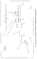
- a hydraulic system is shown in the measures to reduce pressure pulsations and structure-borne noise are implemented.
- the hydraulic medium like for example hydraulic oil, promoted by means of a hydraulic pump 31. Due to the non-uniform flow rate of the hydraulic pump and the resulting pressure pulsations become the walls of the hydraulic system is excited to vibrate. Hereby there is an emission of airborne sound and thus one noisy environment.
- the illustrated Hydraulic system through the walls of the pipe 33 the pulsation of the liquid flow is excited to vibrate. Furthermore, vibrations in the hydraulic pump 31 itself arise, transferred.
- the flow pulsation should be smoothed out.
- a pulsation reducer 35 for example as an expansion hose or as a storage element is carried out, as at the beginning with reference to various European Patent specifications explained.
- Fig. 1st a Insulation of structure-borne noise to ensure what is shown in Fig. 1st is referred to as device 39.
- this device as shown downstream to integrate the insulation of liquid pulsations is because the walls otherwise due to pressure pulsations of the system are excited to vibrate again, resulting in a Structure-borne noise.
- this Device 39 for the insulation of structure-borne noise are the following Pipelines 40 and 42 almost free of vibrations or Structure-borne sound waves, which is also a consumption example 4/3-way valve 41 and the synchronous cylinder 43 free of Structure-borne noise.
- the hydraulic medium is in the final pipeline 45 again the reservoir 29 fed.
- Fig. 2 is now one for the purpose of structure-borne sound insulation developed device shown in longitudinal section.
- Structure-borne noise insulation is essentially through a perfect Separation of the metallic surfaces of the pipes, for example 1 and 6 achieved with the help of an intermediate medium 3.
- the tube 1 transmits the vibrations generated on the pump 31 (Structure-borne noise).
- the intermediate medium 3 preferably has a very much lower density than the pipe material. By the difference in density from tube 1 and intermediate medium 3 are the incoming Sound waves are largely reflected at their interface and only passed on to a small extent through the intermediate medium 3. Added to this is the damping property (absorption) of the intermediate medium, which is preferably to be executed soft, whereby additional sound energy is dissipated.
- the interface between the intermediate medium 3 and the tube 6 are used for reflection of sound waves that are transmitted in the intermediate medium.
- the intermediate medium can result from the shape of the pipe ends not be ousted. It arises at the dividing surfaces 13, 14, 15 and 16 an additional pressing of the intermediate medium and the pipe ends that support the sealing function.
- the level of structure-borne noise insulation significantly from the insulation of the liquid pulsations may depend on the poor insulation of the liquid pulsation to structure-borne noise in the system downstream of the Structure-borne noise insulation can result.
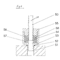
- FIG. 3 shows a further embodiment variant of a decoupling device, which in a pump housing for decoupling the vibrations and / or on a downstream of the pulsation damper Consumer can be screwed in.
- 3 are the pump housing or the consumer through the flange 51 represents.
- the most important aspects regarding the function of the decoupling element are also met here. How even in the element shown in Fig. 2, the perfect Separation of the metallic surfaces achieved.
- the end of the tube 50 in turn has a projection, which by a disc 54 is formed, which by a welding or Solder connection is firmly connected to the tube 50.
- This version of the pipe end is more technically feasible.
- the sealing function is also supported here. Will that be Pressurized fluid-carrying line 20, so it will rubber-elastic intermediate medium, formed by a disc-shaped Element 57, displaced radially outwards.
- the intermediate medium prevented a radial flow movement, and it builds up the annular nose on a surface pressure, which the Sealing function supports.
- the intermediate medium area 56 also designed as an annular element 56, which is axially pressed by the deformation of the ring 57 and its possible flow movement through this compression in the radial direction (towards the pipe axis) also through the nose-shaped design of the discs is additionally hindered. This also leads to an increased surface pressure of the intermediate medium on the disc-shaped projection 54 and one Nut 55, which supports the sealing function.
- the socket 53 is screwed into the flange 51, which annular housing 52 of the seal of this screw serves. This is when screwing pipes in steering gear and pump of a power steering state of the art.
- FIG. 4 shows a graphic for demonstrating the function of a decoupling element, for example shown in FIG. 2.
- Two measurements are shown, which were determined in a system which corresponds to that in FIG. 1.
- the acceleration of the pipe wall perpendicular to the pipe axis ie in the radial direction of the pipe cross-section, was measured with piezoelectric accelerometers.
- the first measuring point is in the pipe section 33, and here the signal a 1 was recorded.
- the second measuring point lies in the pipe section 40, and here the signal a 2 was recorded.
- the dotted line 61 shows the transfer function of an expansion hose 35 without a decoupling element 39 connected downstream. It can be seen that the transfer function is even higher than 1 (or 0 dB) and consequently the vibrations in the pipeline section 39 are stronger than in section 33. This is an indication that the expansion hose, although its good reduction in pressure pulsations, is the transmission of structure-borne noise not prevented.
- the solid curve 63 shows the same transfer function for the system in which the decoupling element 39 was connected downstream of the expansion hose 35. There is a significant reduction in pipe vibration in section 40 (a 1 ) compared to section 33 (a 2 ).
- FIGS. 2 and 3 act it is of course only examples to explain the present invention. It goes without saying that the interrupted pipeline is also a plastic line, however, the problem of structure-borne noise transmission can be less serious in plastic pipes.
- the interpretation the device in the case of using, for example reinforced plastic pipes is similar to those shown in Figs. 2 and 3, again by an intermediate medium is selected whose density is less than the density of the polymer material from which the pipeline is made is.
- the envelope encompassing the device on the outside or the ring-shaped connection socket 53 does not necessarily have to be made of metal be made, but also for example reinforced polymer material can be used.
- Disposable items can be the sleeve or the nut during assembly the intermediate medium can be arranged in a pressing manner, for example by means of shrinking, pressing or injection molding technology.
- the screws shown can also be rivets, for example are used, as well as other assembly elements.
- Suitable damping materials are certainly NBR Rubber, silicones, polyurethanes and other thermoplastic or thermosetting elastomers in question, but it is clear that the material used meets the required criterion which should have a lower density and be flexible. At a possible series production, there are many other factors, such as. Temperature and abrasion resistance, a role play, as a matter of course also the applicability by means of simplest manufacturing technology.
- instead of two or more intermediate rings are arranged from an intermediate ring be, of course also an execution without intermediate ring is quite conceivable, such as in Fig. 3 shown.
Abstract
Description
Die vorliegende Erfindung betrifft eine Anordnung zur Reduktion von Körperschallübertragungen in einer ein fluides Medium führenden Leitung und insbesondere eine Vorrichtung zur Reduktion der Körperschallübertragung in Hydrauliksystemen bzw. Hydraulikleitungen bei hohen Drücken.The present invention relates to an arrangement for reduction of structure-borne noise in a fluid medium Pipe and in particular a device for reduction structure-borne noise transmission in hydraulic systems or hydraulic lines at high pressures.
In Hydrauliksystemen, Abgasleitungen bzw. generell in Flüssigkeiten oder Gasen führenden Leitungssystemen besteht oft das Problem der Übertragung bzw. des Fortlaufens von Vibrationen, Schallwellen und dergleichen. Diese werden beispielsweise verursacht durch Pumpen, stossweise geführte Flüssigkeiten oder Gase etc.In hydraulic systems, exhaust pipes or generally in liquids or gas-carrying piping systems often exists Problem of the transmission or the continuation of vibrations, Sound waves and the like. These are caused, for example by pumps, intermittent liquids or Gases etc.
Im speziellen und beispielsweise soll diese Problematik anhand von Hydrauliksystemen beschrieben werden. Aufgrund des ungleichförmigen Förderstromes beispielsweise von Verdrängerpumpen in Hydrauliksystemen und den daraus resultierenden Druckpulsationen werden die Wandungen eines Hydrauliksystems zu Schwingungen angeregt. Hierdurch kommt es zu einer Emission von Luftschall und somit zu einer geräuschlichen Beeinträchtigung der Umgebung. In Hydrauliksystemen werden beispielsweise die Wandungen von Rohrleitungen durch die Pulsation des Flüssigkeitsstromes zu Schwingungen angeregt. Weiterhin werden Schwingungen, die in der Hydropumpe selbst entstehen, übertragen. Um die Schallabstrahlung in nachgeschalteten Systemen, wie z.B. in einem Hydrozylinder bzw. generell bei einem Verbraucher oder den verbindenden Rohrleitungen, zu vermeiden, ist somit die Förderstrompulsation zu glätten. Dies kann beispielsweise mit Hilfe eines Pulsationsminderers erfolgen, der als Dehnschlauch oder als Speicherelement ausgeführt ist. Derartige Pulsationsminderer, wie beispielsweise Dehnschläuche, sind aus der EP 426 789 bzw. der EP 471 044 bekannt. Adaptive passive und aktive Pulsationsdämpfer mit Speicherelement sind aus der EP 679 832 bzw. EP 633 400 bekannt. Der Einbauort sollte dabei möglichst nahe an der Pulsationsquelle (Hydropumpe) liegen. Erfolgt mit dieser Massnahme eine Glättung der Flüssigkeitspulsation, so werden in nachgeschalteten Systemen die Wandungen nicht mehr zu Schwingungen angeregt. Die Schwingungen, die in der Rohrleitung bzw. in der Hydropumpe entstehen, werden jedoch über den Pulsationsminderer hinweg übertragen, sofern dieser keine ausreichende Dämmung der Körperschallübertragung gewährleistet. Als Pulsationsminderer mit geringer Körperschallübertragung in Hydrauliksystemen mit hohem Betriebsdruck werden nach dem aktuellen Stand der Technik Dehnschläuche eingesetzt. Diese besitzen zur Gewährleistung der Druckfestigkeit Einlagen aus Kunststoffgewebe, die unter hohem Betriebsdruck gespannt werden und Körperschall in begrenztem Masse übertragen. Dieser breitet sich in nachgeschalteten Systemen aus und führt somit zu Restschwingungen und zur Abstrahlung von Luftschall in der gesamten Struktur. Um eine geräuschliche Beeinträchtigung der Umgebung weitgehendst zu verhindern, ist neben der Glättung von Flüssigkeitspulsation folglich auch für eine Dämmung der Körperschallübertragung zu sorgen.In particular and for example, this problem should be based on be described by hydraulic systems. Because of the non-uniform Flow rate, for example of positive displacement pumps in hydraulic systems and the resulting pressure pulsations become the walls of a hydraulic system Vibrations stimulated. This leads to an emission of Airborne sound and thus to a noise impairment the environment. In hydraulic systems, for example Pipe walls due to the pulsation of the liquid flow stimulated to vibrate. Furthermore, vibrations, that arise in the hydraulic pump itself. Around the sound radiation in downstream systems, e.g. in a hydraulic cylinder or generally at a consumer or avoiding the connecting pipelines is therefore the Smooth flow flow pulsation. This can be done with, for example A pulsation reducer can be used as an expansion hose or is designed as a storage element. Such pulsation reducers, such as expansion hoses are from EP 426 789 or EP 471 044. Adaptive passive and active Pulsation dampers with a memory element are from EP 679 832 or EP 633 400 known. The installation location should be as possible close to the pulsation source (hydraulic pump). Success with this measure a smoothing of the liquid pulsation, so the walls in downstream systems are no longer closed Vibrations stimulated. The vibrations in the pipeline or arise in the hydraulic pump, but are via the pulsation reducer transferred if this is not sufficient Insulation of structure-borne noise guaranteed. As Pulsation reducer with low structure-borne noise transmission in hydraulic systems with high operating pressure according to the current State of the art expansion hoses used. Own them inserts made of plastic fabric to ensure pressure resistance, which are tensioned under high operating pressure and structure-borne noise transferred to a limited extent. This spreads in downstream systems and thus leads to residual vibrations and to radiate airborne sound throughout Structure. To have a noisy environment To prevent as much as possible is to smooth out liquid pulsation consequently also for insulation of structure-borne noise transmission to care.
Zur Dämmung derartiger Schallübertragungen wird beispielsweise
in der US 3 936 078 ein Dämpfungselement beschrieben, wobei in
einem Leitungsunterbruch elastisches Material zwischen zwei
speziell ausgebildeten Anschlussenden vorgesehen ist. Weitere
analoge Dämpfungselemente werden in der EP 575 727 sowie der US
4 045 057 beschrieben. Aus der US 5 639 127 sowie der EP 0 615
595 sind Dämpfungsanordnungen bekannt speziell geeignet bei Abgasanlagen
von Kraftfahrzeugen.For the insulation of such sound transmissions, for example
in US 3 936 078 describes a damping element, wherein in
a line break between elastic material
specially designed connection ends is provided. Further
Analog damping elements are described in EP 575 727 and US
4,045,057. From US 5 639 127 and
Die Aufgabe der vorliegenden Erfindung besteht nun im Schaffen einer Anordnung zur Reduktion von Vibrations- bzw. Körperschallwellenübertragung in fluide Medien führenden Leitungen, welche insbesondere geeignet ist in Hydrauliksystemen mit hohen Betriebs- bzw. Arbeitsdrücken.The object of the present invention is to create an arrangement for reducing vibration or structure-borne sound wave transmission lines carrying fluids, which is particularly suitable in hydraulic systems with high Operating or working pressures.
Erfindungsgemäss wird die gestellte Aufgabe mittels einer Anordnung gemäss dem Wortlaut nach Anspruch 1 gelöst.According to the invention, the object is achieved by means of an arrangement solved according to the wording of claim 1.
Vorgeschlagen wird, dass zur Reduktion von Körperschallübertragungen in einer ein fluides Medium führenden Leitung ein Trennbereich vorgesehen ist, der die das fluide Medium führende Leitung unterbricht, aufweisend eine Verbindungsanordnung zum Verbinden der beiden entsprechenden Anschlussenden der getrennten Leitung. Dieser Trennbereich besteht mindestens aus einem Zwischenmedium mit einem die beiden Leitungen verbindenden, dichten Leitungsabschnitt sowie aus Mitteln, um das Zwischenmedium zu verpressen bzw. um einen Druck auf dieses Zwischenmedium auszuführen.It is proposed to reduce structure-borne noise a separation area in a line carrying a fluid medium is provided, which is the line carrying the fluid medium interrupts, comprising a connection arrangement for connection of the two corresponding connection ends of the separate Management. This separation area consists of at least one intermediate medium with a tight, connecting the two lines Line section as well as funds to the intermediate medium to compress or to apply pressure to this intermediate medium to execute.
Das Zwischenmedium weist dabei vorzugsweise eine geringere Dichte auf als das Leitungsmaterial, um eine Dämpfung der Schallübertragung zu erzielen. Aufgrund der Verpressung ergibt sich, dass das Zwischenmedium im unmontierten Zustand ein grösseres Volumen aufweist als im mittels der Mittel zum Verpressen montierten Zustand.The intermediate medium preferably has a lower one Density on than the conduit material to attenuate the Achieve sound transmission. Because of the pressing results that the intermediate medium is a larger one in the unmounted state Has volume than in the means for pressing assembled condition.
Weiter wird vorgeschlagen, dass zwischen den Anschlussenden der unterbrochenen Leitung ein unelastischer Zwischenring angeordnet ist, welcher vorzugsweise eine höhere Dichte aufweist als das Zwischenmedium.It is further proposed that between the connection ends of the interrupted line arranged an inelastic intermediate ring , which preferably has a higher density than the intermediate medium.
Gemäss einer bevorzugten Ausführungsvariante besteht das Zwischenmedium aus einem weichen oder elastischen Material.According to a preferred embodiment variant, there is the intermediate medium made of a soft or elastic material.
Weitere bevorzugte Ausführungsvarianten der erfindungsgemäss definierten Anordnung sind in den abhängigen Ansprüchen definiert.Further preferred embodiments of the invention defined arrangement are defined in the dependent claims.
Ein Unterschied der erfindungsgemäss vorgeschlagenen Anordnung im Vergleich zu all den diversen Dämpfungselementen und Einrichtungen, bekannt aus dem Stand der Technik, besteht darin, dass das zwischen den Anschlussenden der unterbrochenen Leitung angeordnete Zwischenmedium im montierten Zustand der Anordnung verpresst ist. Dadurch entsteht an den Trennflächen von Zwischenmedium und Anschlussenden bzw. dem Zwischenring eine Flächenpressung, welche die Dichtfunktion unterstützt.A difference in the arrangement proposed according to the invention compared to all the various damping elements and devices, known from the prior art, consists in that that is between the connection ends of the broken line arranged intermediate medium in the assembled state of the arrangement is pressed. This creates intermediate medium separating surfaces and connection ends or the intermediate ring a surface pressure, which supports the sealing function.
Entsprechend eignet sich die erfindungsgemäss vorgeschlagene Anordnung insbesondere für die Reduktion von Vibrations- bzw. Schallwellenübertragungen in Hydrauliksystemen mit hohen Drükken.Accordingly, the one proposed according to the invention is suitable Arrangement especially for the reduction of vibration or Sound wave transmissions in hydraulic systems with high pressures.
Die Erfindung wird nun beispielsweise und unter Bezug auf die beigefügten Figuren näher erläutert. Dabei zeigen:
- Fig. 1:
- Schematisch dargestellt, ein Hydrauliksystem mit Elementen zur Dämmung von Flüssigkeitspulsationen und Körperschall,
- Fig. 2:
- eine erfindungsgemässe Vorrichtung zur Dämmung von Körperschall bzw. Vibrationen,
- Fig. 3:
- eine weitere erfindungsgemässe Vorrichtung, unmittelbar angeschlossen an ein Pumpengehäuse zur Entkoppelung der Schwingungen, und
- Fig. 4:
- eine graphische Darstellung zum Nachweis der Funktion einer erfindungsgemässen Entkoppelungsvorrichtung.
- Fig. 1:
- Shown schematically, a hydraulic system with elements for insulating liquid pulsations and structure-borne noise,
- Fig. 2:
- a device according to the invention for the insulation of structure-borne noise or vibrations,
- Fig. 3:
- another device according to the invention, directly connected to a pump housing for decoupling the vibrations, and
- Fig. 4:
- a graphic representation to demonstrate the function of a decoupling device according to the invention.
In Fig. 1 ist ein Hydrauliksystem dargestellt, in dem Massnahmen
zur Minderung von Druckpulsationen und Körperschallübertragung
implementiert sind. Dabei wird das Hydraulikmedium, wie
beispielsweise Hydrauliköl, mittels einer Hydropumpe 31 gefördert.
Aufgrund des ungleichförmigen Förderstroms der Hydropumpe
und den daraus resultierenden Druckpulsationen werden die Wandungen
des Hydrauliksystems zu Schwingungen angeregt. Hierdurch
kommt es zu einer Emission von Luftschall und somit zu einer
geräuschlichen Beeinträchtigung der Umgebung. Im dargestellten
Hydrauliksystem werden die Wandungen der Rohrleitung 33 durch
die Pulsation des Flüssigkeitsstromes zu Schwingungen angeregt.
Weiterhin werden Schwingungen, die in der Hydropumpe 31 selbst
entstehen, übertragen. Um die Schallabstrahlung in nachgeschalteten
Systemen, wie beispielsweise dem in Fig. 1 dargestellten
Gleichgangzylinder 43 oder den verbindenden Rohrleitungen 40
und 42, zu vermeiden, ist die Förderstrompulsation zu glätten.
Dies geschieht zunächst mit Hilfe eines Pulsationsminderers 35,
der beispielsweise als Dehnschlauch oder als Speicherelement
ausgeführt ist, wie eingangs unter Bezug auf diverse europäische
Patentschriften näher erläutert. Die Schwingungen, die in
der Rohrleitung 33 bzw. in der Hydropumpe entstehen, werden jedoch
über den Pulsationsminderer 35 hinweg übertragen, sofern
dieser keine ausreichende Dämmung der Körperschallübertragung
gewährleistet. Speziell bei hohem Betriebsdruck sind die aus
dem Stand der Technik bekannten Pulsationsminderer nicht geeignet,
Körperschall ausreichend zu dämpfen, womit dieser im begrenzten
Masse auf Rohrleitung 37 übertragen wird. Dieser breitet
sich somit im nachgeschalteten System aus und führt somit
zu Restschwingungen und zur Abstrahlung von Luftschall in der
gesamten Struktur. Um eine geräuschliche Beeinträchtigung der
Umgebung weitgehendst zu verhindern, ist neben der Glättung von
Flüssigkeitspulsationen im Dämpfer 35 folglich auch für eine
Dämmung der Körperschallübertragung zu sorgen, was in Fig. 1
als Vorrichtung 39 bezeichnet wird. Dabei handelt es sich um
die erfindungsgemäss vorgeschlagene Vorrichtung zur Dämmung von
Körperschall, wobei diese Vorrichtung wie dargestellt stromabwärts
der Dämmung von Flüssigkeitspulsationen zu integrieren
ist, da ansonsten infolge von Druckpulsationen die Wandungen
des Systems erneut zu Schwingungen angeregt werden, was zu einer
Entstehung von Körperschall führt. Durch Anordnen dieser
Vorrichtung 39 zur Dämmung von Körperschall sind die nachfolgenden
Rohrleitungen 40 und 42 nahezu frei von Vibrationen bzw.
Körperschallwellen, womit auch verbraucherseits ein beispielsweise
4/3-Wegventil 41 sowie der Gleichgangzylinder 43 frei von
Körperschall sind. Schlussendlich wird das Hydraulikmedium in
der abschliessenden Rohrleitung 45 erneut dem Vorratsbehälter
29 zugeführt.In Fig. 1, a hydraulic system is shown in the measures
to reduce pressure pulsations and structure-borne noise
are implemented. The hydraulic medium, like
for example hydraulic oil, promoted by means of a
In Fig. 2 nun ist eine für den Zweck der Körperschalldämmung
entwickelte Vorrichtung im Längsschnitt dargestellt. Die Körperschalldämmung
wird im wesentlichen durch eine vollkommene
Trennung der beispielsweise metallischen Oberflächen der Rohrleitungen
1 und 6 mit Hilfe eines Zwischenmediums 3 erreicht.
Das Rohr 1 überträgt die an der Pumpe 31 erzeugten Schwingungen
(Körperschall). Das Zwischenmedium 3 hat eine vorzugsweise sehr
viel geringere Dichte als das Rohrmaterial. Durch den Dichteunterschied
von Rohr 1 und Zwischenmedium 3 werden die ankommenden
Schallwellen an deren Trennfläche zum Grossteil reflektiert
und nur zu einem geringen Teil durch das Zwischenmedium 3 weitergeleitet.
Hinzu kommt die Dämpfungseigenschaft (Absorption)
des vorzugsweise weich auszuführenden Zwischenmediums, wodurch
zusätzlich Schallenergie dissipiert wird. Die Trennfläche zwischen
dem Zwischenmedium 3 und dem Rohr 6 dient der Reflexion
von Schallwellen, die im Zwischenmedium übertragen werden.In Fig. 2 is now one for the purpose of structure-borne sound insulation
developed device shown in longitudinal section. Structure-borne noise insulation
is essentially through a perfect
Separation of the metallic surfaces of the pipes, for example
1 and 6 achieved with the help of an
Durch die Elastizität des Zwischenmediums übernimmt dieses zusätzlich
eine Dichtfunktion. Zur Sicherung der Dichtheit auch
bei hohen Drücken sind die Rohrenden 7 und 8 wie dargestellt
ausgeführt. Durch das Verschrauben einer aussen umgreifenden
Hülle 2 mit einem Deckel 5 wird das elastische Zwischenmedium,
welches im unmontierten Zustand ein grösseres als das dargestellte
Volumen besitzt, verpresst. Aufgrund der ausgeführten
Rohrenden kommt es im Bereich der dargestellten überstehenden
Nasen 9, 10, 11 und 12 zu einer erhöhten Pressung des Zwischenmediums.
Um diese auch über der gesamten Distanz, die die beiden
Rohrenden voneinander trennt, aufrechtzuerhalten, ist vorzugsweise
ein unelastischer Zwischenring 4 vorzusehen, welcher
ebenfalls beispielsweise aus Metall hergestellt sein kann. Weiterhin
wird bei einer Beaufschlagung des Systems mit hohem
Druck das elastische Zwischenmedium in radialer Richtung verdichtet.
Durch die Querschnittsverengung in radialer Richtung,
die sich aus der Formgebung der Rohrenden ergibt, kann das Zwischenmedium
nicht verdrängt werden. Es entsteht an den Trennflächen
13, 14, 15 und 16 eine zusätzliche Verpressung von Zwischenmedium
und den Rohrenden, die die Dichtfunktion unterstützt. Due to the elasticity of the intermediate medium, this also takes over
a sealing function. To ensure tightness too
at high pressures the pipe ends 7 and 8 are as shown
executed. By screwing one around the
In Messungen mit einem vorgeschalteten Pulsationsminderer (Dämmfaktor 10) konnte gezeigt werden, dass die Schwingungsamplituden im Rohrmaterial um den Faktor 8 reduziert werden konnten.In measurements with an upstream pulsation reducer (Insulation factor 10) it could be shown that the vibration amplitudes in the pipe material can be reduced by a factor of 8 could.
Schliesslich sei darauf hingewiesen, dass die Höhe der Körperschalldämmung massgeblich von der Dämmung der Flüssigkeitspulsationen abhängen kann, da eine mangelhafte Dämmung der Flüssigkeitspulsation zu Körperschall im System stromabwärts der Körperschalldämmung führen kann.Finally, it should be noted that the level of structure-borne noise insulation significantly from the insulation of the liquid pulsations may depend on the poor insulation of the liquid pulsation to structure-borne noise in the system downstream of the Structure-borne noise insulation can result.
Fig. 3 zeigt eine weitere Ausführungsvariante einer Entkoppelungsvorrichtung,
welche in ein Pumpengehäuse zur Entkoppelung
der Schwingungen und/oder an einem dem Pulsationsdämpfer nachgeschalteten
Verbraucher eingeschraubt werden kann. In Fig. 3
sind das Pumpengehäuse oder der Verbraucher durch den Flansch
51 repräsentiert. Die wichtigsten Aspekte bezüglich der Funktion
des Entkoppelungselementes werden auch hier erfüllt. Wie
auch bei dem in Fig. 2 dargestellten Element wird die vollkommene
Trennung der metallischen Oberflächen erreicht. Das Ende
des Rohres 50 weist wiederum eine Aufkragung auf, welche durch
eine Scheibe 54 gebildet wird, welche durch eine Schweiss- oder
Lötverbindung fest mit dem Rohr 50 verbunden ist. Somit ergibt
sich eine ganz ähnliche Geometrie des Rohrendes wie bei denjenigen
dargestellt in Fig. 2. Diese Ausführung des Rohrendes ist
fertigungstechnisch besser durchführbar. Durch die Ausführung
der ringförmigen Nasen 58 an den beiden Stirnseiten der Scheibe
54 wird auch hier die Dichtfunktion unterstützt. Wird die das
Fluid führende Leitung 20 mit Druck beaufschlagt, so wird das
gummielastische Zwischenmedium, gebildet durch ein scheibenförmiges
Element 57, radial nach aussen verdrängt. Durch die nasenförmige
Ausführung der Scheibe 54 wird das Zwischenmedium an
einer radialen Fliessbewegung gehindert, und es baut sich an
der ringförmigen Nase eine Flächenpressung auf, welche die
Dichtfunktion stützt. Ähnliches gilt auch für den Zwischenmediumsbereich
56, ebenfalls ausgebildet als ringförmiges Element
56, welches durch die Verformung des Ringes 57 axial verpresst
wird und dessen durch diese Verpressung mögliche Fliessbewegung
in radialer Richtung (zur Rohrachse hin) ebenfalls durch die
nasenförmige Ausführung der Scheiben zusätzlich behindert wird.
Dies führt auch hier zu einer erhöhten Flächenpressung des Zwischenmediums
an der scheibenförmigen Aufkragung 54 und einer
Mutter 55, welche die Dichtfunktion unterstützt.3 shows a further embodiment variant of a decoupling device,
which in a pump housing for decoupling
the vibrations and / or on a downstream of the pulsation damper
Consumer can be screwed in. 3
are the pump housing or the consumer through the
Auch beim Element gemäss Fig. 3 ist auf einen Dichteunterschied
von Zwischenmedium und Rohrende zu achten, da die durch das
Rohr 50 bzw. die durch den Flansch 51 (beispielsweise bei Einschraubung
in ein Pumpengehäuse) übertragenen Strukturschwingungen
reflektiert werden (Reflexion am offenen Ende). Für das
Zwischenmedium gelten dieselben Kriterien wie bei dem in Fig. 2
dargestellten Element, damit auch die Absorption der Schallwellen
durch das weiche Zwischenmedium bewirkt werden kann. Die
Verpressung des Zwischenmediums erfolgt durch die Mutter 55,
welche in eine Buchse 53 eingeschraubt wird. Die Ringe 56 und
57, gefertigt aus dem beschriebenen Zwischenmedium, werden
folglich durch die Mutter 55 axial in Rohrachsenrichtung verpresst
und haben im nicht eingebauten Zustand ein grösseres Volumen.
Denkbar wäre weiterhin, dass die beiden Ringe 56 und 57
ein gemeinsames Bauteil darstellen, z.B. in Form ein aufvulkanisierten
Wulstes. There is also a density difference in the element according to FIG. 3
of the intermediate medium and pipe end, as the through the
Die Buchse 53 wird in den Flansch 51 eingeschraubt, wobei das
ringförmige Gehäuse 52 der Abdichtung dieser Verschraubung
dient. Dies ist bei Verschraubungen von Rohrleitungen in Lenkgetriebe
und Pumpe einer Servolenkung Stand der Technik.The
Durch die direkte Einschraubung des Elementes in ein Pumpengehäuse und/oder einen Verbraucher entfällt der bisher vorgesehene Rohranschluss, was eine erhebliche Reduktion der Kosten gegenüber dem in Fig. 2 dargestellten Element darstellt.By screwing the element directly into a pump housing and / or a consumer does not have the previously provided Pipe connection, compared to a significant reduction in costs represents the element shown in Fig. 2.
In Fig. 4 schlussendlich ist eine Grafik dargestellt zum Nachweis
der Funktion eines Enkoppelungselementes, beispielsweise
dargestellt in Fig. 2. Dargestellt sind zwei Messungen, welche
in einem System ermittelt wurden, welches jenem in Fig. 1 entspricht.
An zwei Punkten des Rohrleitungssystems wurde mit piezoelektrischen
Beschleunigungsaufnehmern die Beschleunigung der
Rohrwandung senkrecht zur Rohrachse, d.h. in radialer Richtung
des Rohrquerschnittes, gemessen. Die erste Messstelle ist im
Rohrleitungsabschnitt 33, und hier wurde das Signal a1 aufgenommen.
Die zweite Messstelle liegt im Rohrleitungsabschnitt
40, und hier wurde das Signal a2 aufgenommen. Das Verhältnis
von a2 zu a1 über der Frequenz stellt die Übertragungsfunktion
(= Amplitudengang oder Frequenzgang) der Beschleunigung der
Rohrwandung senkrecht zur Rohrachse dar. Dies kann als ein Mass
für die Strukturschwingungen und damit für den Körperschall
herangezogen werden. Mit der punktierten Linie 61 wird die
Übertragungsfunktion eines Dehnschlauches 35 ohne nachgeschaltetes
Entkoppelungselement 39 gezeigt. Man sieht, dass die
Übertragungsfunktion sogar höher als 1 (bzw. 0 dB) wird und
folglich die Schwingungen im Rohrleitungsabschnitt 39 stärker
sind als im Abschnitt 33. Dies ist ein Indiz dafür, dass der
Dehnschlauch, obgleich seiner guten Minderung der Druckpulsationen,
die Körperschallübertragung nicht verhindert. In der
durchgezogenen Kurve 63 ist die gleiche Übertragungsfunktion
für jenes System dargestellt, in dem das Entkoppelungselement
39 dem Dehnschlauch 35 nachgeschaltet wurde. Es zeigt sich eine
erhebliche Minderung der Rohrschwingung im Abschnitt 40 (a1)
gegenüber dem Abschnitt 33 (a2) .Finally, FIG. 4 shows a graphic for demonstrating the function of a decoupling element, for example shown in FIG. 2. Two measurements are shown, which were determined in a system which corresponds to that in FIG. 1. At two points in the pipeline system, the acceleration of the pipe wall perpendicular to the pipe axis, ie in the radial direction of the pipe cross-section, was measured with piezoelectric accelerometers. The first measuring point is in the pipe section 33, and here the signal a 1 was recorded. The second measuring point lies in the
Bei den Vorrichtungen, dargestellt in den Fig. 2 und 3, handelt
es sich selbstverständlich nur um Beispiele zur Erläuterung der
vorliegenden Erfindung. Selbstverständlich kann es sich bei der
unterbrochenen Rohrleitung auch um eine Kunststoffleitung handeln,
wobei allerdings die Problematik der Körperschallübertragung
in Kunststoffrohren weniger gravierend sein kann. Die Auslegung
der Vorrichtung im Falle der Verwendung von beispielsweise
verstärkten Kunststoffrohren ist aber ähnlich denjenigen,
dargestellt in den Fig. 2 und 3, indem wiederum ein Zwischenmedium
gewählt wird, dessen Dichte geringer ist als die Dichte
des Polymermaterials, aus welchem die Rohrleitung hergestellt
ist. Auch die die Vorrichtung aussen umgreifende Hülle bzw. die
ringförmige Anschlussbuchse 53 muss nicht zwingend aus Metall
hergestellt sein, sondern auch dafür kann beispielsweise ein
verstärktes Polymermaterial verwendet werden. Auch muss die in
Fig. 2 dargestellte Hülse bzw. die Mutter 55 aus Fig. 3 nicht
zwingend verschraubbar sein, sondern im Sinne eines sogenannten
Einwegartikels kann die Hülse bzw. die Mutter bei der Montage
des Zwischenmediums verpressend angeordnet werden, beispielsweise
mittels Schrumpf-, Press- oder Spritzgusstechnik. Statt
der dargestellten Schrauben können beispielsweise auch Nieten
verwendet werden, wie auch andere Montageorgane.The devices shown in FIGS. 2 and 3 act
it is of course only examples to explain the
present invention. It goes without saying that the
interrupted pipeline is also a plastic line,
however, the problem of structure-borne noise transmission
can be less serious in plastic pipes. The interpretation
the device in the case of using, for example
reinforced plastic pipes is similar to those
shown in Figs. 2 and 3, again by an intermediate medium
is selected whose density is less than the density
of the polymer material from which the pipeline is made
is. Also the envelope encompassing the device on the outside or the
ring-shaped
Als Zwischenmedium eignen sich insbesondere Elastomere oder gummielastische Polymermaterialien, welche mittels Extrusions-, Spritz- oder Giesstechnik bzw. mittels Aufvulkanisieren zur Bildung der Verbindungsanordnung zum Verbinden der beiden Anschlussenden der getrennten Leitung angeordnet werden können. Als geeignete Dämpfungsmaterialien kommen sicherlich NBR- Kautschuk, Silikone, Polyurethane sowie weitere thermoplastische oder duroplastische Elastomere in Frage, wobei aber feststeht, dass der verwendete Werkstoff das geforderte Kriterium der geringeren Dichte haben sollte und flexibel sein muss. Bei einer eventuellen Serienfertigung werden noch viele andere Faktoren, wie z.B. Temperatur- und Abriebfestigkeit, eine Rolle spielen, wie selbstverständlich auch die Anwendbarkeit mittels einfachster Fertigungstechnik. Schlussendlich können anstelle von einem Zwischenring auch zwei oder mehrere Zwischenringe angeordnet werden, wobei selbstverständlich auch eine Ausführung ohne Zwischenring durchaus denkbar ist, wie beispielsweise in Fig. 3 dargestellt.Elastomers or are particularly suitable as an intermediate medium rubber-elastic polymer materials, which by means of extrusion, Spraying or casting technology or by means of vulcanization for Formation of the connection arrangement for connecting the two connection ends the separate line can be arranged. Suitable damping materials are certainly NBR Rubber, silicones, polyurethanes and other thermoplastic or thermosetting elastomers in question, but it is clear that the material used meets the required criterion which should have a lower density and be flexible. At a possible series production, there are many other factors, such as. Temperature and abrasion resistance, a role play, as a matter of course also the applicability by means of simplest manufacturing technology. Finally, instead of two or more intermediate rings are arranged from an intermediate ring be, of course also an execution without intermediate ring is quite conceivable, such as in Fig. 3 shown.
Claims (12)
Priority Applications (4)
| Application Number | Priority Date | Filing Date | Title |
|---|---|---|---|
| EP99121112A EP1094267A1 (en) | 1999-10-22 | 1999-10-22 | Device for reducing structural noise in pipelines |
| PCT/CH2000/000557 WO2001031248A1 (en) | 1999-10-22 | 2000-10-17 | Device for reducing structure-borne noises in conduits |
| AU76381/00A AU7638100A (en) | 1999-10-22 | 2000-10-17 | Device for reducing structure-borne noises in conduits |
| EP00965711A EP1222422A1 (en) | 1999-10-22 | 2000-10-17 | Device for reducing structure-borne noises in conduits |
Applications Claiming Priority (1)
| Application Number | Priority Date | Filing Date | Title |
|---|---|---|---|
| EP99121112A EP1094267A1 (en) | 1999-10-22 | 1999-10-22 | Device for reducing structural noise in pipelines |
Publications (1)
| Publication Number | Publication Date |
|---|---|
| EP1094267A1 true EP1094267A1 (en) | 2001-04-25 |
Family
ID=8239262
Family Applications (2)
| Application Number | Title | Priority Date | Filing Date |
|---|---|---|---|
| EP99121112A Withdrawn EP1094267A1 (en) | 1999-10-22 | 1999-10-22 | Device for reducing structural noise in pipelines |
| EP00965711A Withdrawn EP1222422A1 (en) | 1999-10-22 | 2000-10-17 | Device for reducing structure-borne noises in conduits |
Family Applications After (1)
| Application Number | Title | Priority Date | Filing Date |
|---|---|---|---|
| EP00965711A Withdrawn EP1222422A1 (en) | 1999-10-22 | 2000-10-17 | Device for reducing structure-borne noises in conduits |
Country Status (3)
| Country | Link |
|---|---|
| EP (2) | EP1094267A1 (en) |
| AU (1) | AU7638100A (en) |
| WO (1) | WO2001031248A1 (en) |
Cited By (4)
| Publication number | Priority date | Publication date | Assignee | Title |
|---|---|---|---|---|
| DE102007026842A1 (en) * | 2007-06-06 | 2008-12-11 | Endress + Hauser Wetzer Gmbh + Co Kg | Device for determining and / or monitoring a measured variable |
| WO2019077940A1 (en) * | 2017-10-18 | 2019-04-25 | 株式会社デンソー | Joint |
| JP2019074204A (en) * | 2017-10-18 | 2019-05-16 | 株式会社デンソー | Joint |
| EP3670991A1 (en) * | 2018-12-17 | 2020-06-24 | Bombardier Inc. | Duct coupling system |
Families Citing this family (1)
| Publication number | Priority date | Publication date | Assignee | Title |
|---|---|---|---|---|
| DE202014102958U1 (en) * | 2014-06-30 | 2015-10-01 | Rehau Ag + Co | Pipe fitting |
Citations (5)
| Publication number | Priority date | Publication date | Assignee | Title |
|---|---|---|---|---|
| FR957514A (en) * | 1950-02-23 | |||
| US2504634A (en) * | 1941-11-17 | 1950-04-18 | Pirelli | Sound and vibrationproof joint for metal tubing |
| GB2016628A (en) * | 1978-02-25 | 1979-09-26 | Karlsruhe Augsburg Iweka | Compensator |
| DE3515768A1 (en) * | 1985-05-02 | 1986-11-06 | Alfred Teves Gmbh, 6000 Frankfurt | High-pressure-proof, metallic pipe connection |
| JPS62151640A (en) * | 1985-12-26 | 1987-07-06 | Toshiba Corp | Vibration damping device |
-
1999
- 1999-10-22 EP EP99121112A patent/EP1094267A1/en not_active Withdrawn
-
2000
- 2000-10-17 AU AU76381/00A patent/AU7638100A/en not_active Abandoned
- 2000-10-17 EP EP00965711A patent/EP1222422A1/en not_active Withdrawn
- 2000-10-17 WO PCT/CH2000/000557 patent/WO2001031248A1/en not_active Application Discontinuation
Patent Citations (5)
| Publication number | Priority date | Publication date | Assignee | Title |
|---|---|---|---|---|
| FR957514A (en) * | 1950-02-23 | |||
| US2504634A (en) * | 1941-11-17 | 1950-04-18 | Pirelli | Sound and vibrationproof joint for metal tubing |
| GB2016628A (en) * | 1978-02-25 | 1979-09-26 | Karlsruhe Augsburg Iweka | Compensator |
| DE3515768A1 (en) * | 1985-05-02 | 1986-11-06 | Alfred Teves Gmbh, 6000 Frankfurt | High-pressure-proof, metallic pipe connection |
| JPS62151640A (en) * | 1985-12-26 | 1987-07-06 | Toshiba Corp | Vibration damping device |
Non-Patent Citations (1)
| Title |
|---|
| PATENT ABSTRACTS OF JAPAN vol. 011, no. 380 (M - 650) 11 December 1987 (1987-12-11) * |
Cited By (7)
| Publication number | Priority date | Publication date | Assignee | Title |
|---|---|---|---|---|
| DE102007026842A1 (en) * | 2007-06-06 | 2008-12-11 | Endress + Hauser Wetzer Gmbh + Co Kg | Device for determining and / or monitoring a measured variable |
| US8534912B2 (en) | 2007-06-06 | 2013-09-17 | Endress + Hauser Wetzer Gmbh + Co. Kg | Apparatus for determining and/or monitoring a measured variable |
| WO2019077940A1 (en) * | 2017-10-18 | 2019-04-25 | 株式会社デンソー | Joint |
| JP2019074204A (en) * | 2017-10-18 | 2019-05-16 | 株式会社デンソー | Joint |
| JP7135601B2 (en) | 2017-10-18 | 2022-09-13 | 株式会社デンソー | Joint |
| EP3670991A1 (en) * | 2018-12-17 | 2020-06-24 | Bombardier Inc. | Duct coupling system |
| US11248727B2 (en) * | 2018-12-17 | 2022-02-15 | Bombardier Inc. | Duct coupling system |
Also Published As
| Publication number | Publication date |
|---|---|
| AU7638100A (en) | 2001-05-08 |
| EP1222422A1 (en) | 2002-07-17 |
| WO2001031248A1 (en) | 2001-05-03 |
Similar Documents
| Publication | Publication Date | Title |
|---|---|---|
| DE102010060981B3 (en) | Pipe flange used in e.g. chemical plant, has screws that are inserted into through-holes of plastic flange portions, to connect flange portions with counter-element under force application of sealing ring | |
| EP3227152B1 (en) | Pressure modifying dampener for a hydraulic brake system and corresponding brake system | |
| DE60306883T2 (en) | Backlash-free support ring for elastomer seal and flange | |
| DE2106359A1 (en) | Arrangement of a silencer on a compressor | |
| DE102006049594A1 (en) | Flange connection for pipelines | |
| DE4042201C1 (en) | ||
| EP1918626B1 (en) | Accumulator for damping pressure pulsations | |
| EP0237758A2 (en) | Seal | |
| EP1094267A1 (en) | Device for reducing structural noise in pipelines | |
| DE102013223060A1 (en) | Device for fastening of fluid conduit at flange of housing of hydraulic force-strengthened aggregate i.e. brake device for motor car, has connector is arranged between seal and bracket, which is secured at flange for holding fluid conduit | |
| EP2982896A1 (en) | Highly sound absorbing fastening device for pipes | |
| DE60214775T2 (en) | FLANGED MEMBER WITH A FIRST FLANGED END THAT IS CARRIED OUT IN A RADIAL DIRECTION WITH A CONCAVE END SURFACE, AND A FLANGET-CONNECTING FLANGE CONNECTION | |
| WO2011124405A1 (en) | Annular seal element | |
| EP1384935A1 (en) | Flexible connecting piece for pipes, made of elastically deformable material | |
| EP1398554B1 (en) | Hose and method of manufacturing the same | |
| EP0842357B1 (en) | Static seal for internal combustion engines, in particular closure cover for crankshaft and gearbox housings | |
| EP2841887A1 (en) | Measuring tube for a flow meter | |
| DE102011119513A1 (en) | Pipe connection for fluid-tight connection of components of an air conditioner | |
| DE102018203450B4 (en) | Sealing arrangement, fluid control valve with such a sealing arrangement and use of such a fluid control valve | |
| DE102006060215B4 (en) | Line arrangement with a seal in the overlap area | |
| DE102016012297A1 (en) | Reinforced concrete structure | |
| DE202012013675U1 (en) | Device for sealing an annular space between a media pipe / cable and a core bore / protective tube | |
| EP1686305A1 (en) | Device for compensating the relative movement of two pipes that are to be connected in a pressure-tight way | |
| DE102008055512A1 (en) | Air spring for e.g. towing vehicle, has fastening bead whose lower side is provided against shoulder of piston, and circulating sealing rib arranged on shoulder between cone seat and rolling edge of piston | |
| DE19943473B4 (en) | sealing device |
Legal Events
| Date | Code | Title | Description |
|---|---|---|---|
| PUAI | Public reference made under article 153(3) epc to a published international application that has entered the european phase |
Free format text: ORIGINAL CODE: 0009012 |
|
| AK | Designated contracting states |
Kind code of ref document: A1 Designated state(s): AT BE CH CY DE DK ES FI FR GB GR IE IT LI LU MC NL PT SE |
|
| AX | Request for extension of the european patent |
Free format text: AL;LT;LV;MK;RO;SI |
|
| AKX | Designation fees paid | ||
| REG | Reference to a national code |
Ref country code: DE Ref legal event code: 8566 |
|
| STAA | Information on the status of an ep patent application or granted ep patent |
Free format text: STATUS: THE APPLICATION IS DEEMED TO BE WITHDRAWN |
|
| 18D | Application deemed to be withdrawn |
Effective date: 20011026 |