EP1094231A1 - Dispositif de liaison mécanique d'un organe de jonction à un profilé métallique, et procédé d'assemblage - Google Patents
Dispositif de liaison mécanique d'un organe de jonction à un profilé métallique, et procédé d'assemblage Download PDFInfo
- Publication number
- EP1094231A1 EP1094231A1 EP00410117A EP00410117A EP1094231A1 EP 1094231 A1 EP1094231 A1 EP 1094231A1 EP 00410117 A EP00410117 A EP 00410117A EP 00410117 A EP00410117 A EP 00410117A EP 1094231 A1 EP1094231 A1 EP 1094231A1
- Authority
- EP
- European Patent Office
- Prior art keywords
- profile
- hole
- fitted
- junction
- blocking
- Prior art date
- Legal status (The legal status is an assumption and is not a legal conclusion. Google has not performed a legal analysis and makes no representation as to the accuracy of the status listed.)
- Granted
Links
- 238000000034 method Methods 0.000 title claims abstract description 12
- 239000002184 metal Substances 0.000 title claims description 11
- 229910000831 Steel Inorganic materials 0.000 claims abstract description 9
- 239000010959 steel Substances 0.000 claims abstract description 9
- 229910001092 metal group alloy Inorganic materials 0.000 claims abstract description 5
- 230000000903 blocking effect Effects 0.000 claims description 15
- 230000015572 biosynthetic process Effects 0.000 claims description 3
- 239000007787 solid Substances 0.000 claims description 3
- 230000000694 effects Effects 0.000 claims description 2
- 230000005226 mechanical processes and functions Effects 0.000 abstract 1
- 241000920340 Pion Species 0.000 description 2
- 229910000842 Zamak Inorganic materials 0.000 description 1
- 230000002787 reinforcement Effects 0.000 description 1
- 238000003466 welding Methods 0.000 description 1
Images
Classifications
-
- H—ELECTRICITY
- H02—GENERATION; CONVERSION OR DISTRIBUTION OF ELECTRIC POWER
- H02B—BOARDS, SUBSTATIONS OR SWITCHING ARRANGEMENTS FOR THE SUPPLY OR DISTRIBUTION OF ELECTRIC POWER
- H02B1/00—Frameworks, boards, panels, desks, casings; Details of substations or switching arrangements
- H02B1/01—Frameworks
-
- F—MECHANICAL ENGINEERING; LIGHTING; HEATING; WEAPONS; BLASTING
- F16—ENGINEERING ELEMENTS AND UNITS; GENERAL MEASURES FOR PRODUCING AND MAINTAINING EFFECTIVE FUNCTIONING OF MACHINES OR INSTALLATIONS; THERMAL INSULATION IN GENERAL
- F16B—DEVICES FOR FASTENING OR SECURING CONSTRUCTIONAL ELEMENTS OR MACHINE PARTS TOGETHER, e.g. NAILS, BOLTS, CIRCLIPS, CLAMPS, CLIPS OR WEDGES; JOINTS OR JOINTING
- F16B19/00—Bolts without screw-thread; Pins, including deformable elements; Rivets
- F16B19/04—Rivets; Spigots or the like fastened by riveting
- F16B19/06—Solid rivets made in one piece
-
- F—MECHANICAL ENGINEERING; LIGHTING; HEATING; WEAPONS; BLASTING
- F16—ENGINEERING ELEMENTS AND UNITS; GENERAL MEASURES FOR PRODUCING AND MAINTAINING EFFECTIVE FUNCTIONING OF MACHINES OR INSTALLATIONS; THERMAL INSULATION IN GENERAL
- F16B—DEVICES FOR FASTENING OR SECURING CONSTRUCTIONAL ELEMENTS OR MACHINE PARTS TOGETHER, e.g. NAILS, BOLTS, CIRCLIPS, CLAMPS, CLIPS OR WEDGES; JOINTS OR JOINTING
- F16B5/00—Joining sheets or plates, e.g. panels, to one another or to strips or bars parallel to them
- F16B5/0096—Joining sheets or plates, e.g. panels, to one another or to strips or bars parallel to them by using permanent deformation
-
- H—ELECTRICITY
- H02—GENERATION; CONVERSION OR DISTRIBUTION OF ELECTRIC POWER
- H02B—BOARDS, SUBSTATIONS OR SWITCHING ARRANGEMENTS FOR THE SUPPLY OR DISTRIBUTION OF ELECTRIC POWER
- H02B1/00—Frameworks, boards, panels, desks, casings; Details of substations or switching arrangements
- H02B1/01—Frameworks
- H02B1/014—Corner connections for frameworks
Definitions
- the invention relates to a method of assembling a hollow metal profile made of sheet steel on a junction member formed by a solid piece of metal alloy. Such a process can be used to make a device for connecting the uprights and crosspieces of a frame electrical cabinet.
- the removable connections are generally made by screwing by means of screw elements or screw nut. It is necessary to ensure the individual tightening of each screw or nut to obtain good mechanical rigidity of the frame. In the case of a chassis delivered as a kit, the time mounting such a chassis is relatively long.
- the non-removable connections are made by welding, riveting. These operations are the most often operated in the factory, when the chassis is delivered assembled.
- the object of the invention is to develop an improved method of assembling a profile hollow metallic sheet steel on a junction member formed by a solid piece of metal alloy.
- a steel blocking pin having a diameter corresponding to the diameter of the hole reduced by twice the thickness of the sheet.
- the the blocking pin is put in place by means of a hammer so as to obtain a rigid and non-removable assembly.
- the invention also relates to a device for mechanical connection of a junction member to a metal profile constituting an upright and / or a cross member of a cabinet frame electric.
- the mechanical connection device is characterized in that the junction member is formed by a bipod comprising a first connecting part fitted into the upright, and a second connecting piece introduced into the cross member to form a square assembly.
- the blocking pin is put in place to ensure positive locking of the bipod on said connecting pieces.
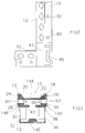
- an upright 10 intended to serve as a pillar for a chassis metal of an electrical cabinet, has a hollow profile 12 in sheet steel, and has a quadrangular section.
- the cut sheet is folded in the longitudinal direction to form four faces 14A, 14B, 14C, 14D parallel two by two.
- the first side 14A has two protrusions 16, 18 having converging edges 20, 22 constituting a bowl. Inside the profile, the two protrusions 16, 18 form corners 24, 26 in forms of dihedrons making an angle of the order of 45 °.
- the second face 14B comprises a first plane wing 28 connected in the middle zone by a recess 30 to a second wing 32 parallel. The first wing 28 projects from the second wing 32, and delimits the protrusion 16 with the inclined edge 20 of the face 14A.
- the third face 14C is provided a substantially planar external surface.
- the profile of the fourth face 14D is symmetrical to that of the second face 14B with respect to in the median plane perpendicular to the first and third faces 14A, 14C.
- the first wing 34 plane is connected by a recess 36 to a second parallel wing 38.
- the first wing 34 projects from the second wing 38, and delimits the protuberance 18 with the inclined edge 22 of the face 14A.
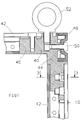
- a rigid junction bipod 40 makes it possible to secure the upright 10 to a crosspiece 42 formed by a quadrangular hollow profile, which is oriented perpendicular to the upright 10.
- the junction bipod 40 has a first connecting piece 44 fitted in the upright 10, and a second connecting piece 46 introduced into the crosspiece 42 of so as to constitute a square assembly.
- the junction bipod 40 is produced by a massive piece of cast metal alloy, especially Zamak.
- a beam 48 is fixed to the junction bipod 40 by a screw 50, and extends perpendicular to the upright 10 and the crosspiece 42.
- a lifting ring 52 can also be screwed onto the upper face of the second connecting piece 46 to facilitate handling of the frame.
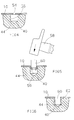
- the steel sheet has a thickness of the order of 2.5 mm, and has at least one orifice 54 circular having a diameter less than that of a blind hole 56 drilled in the bipod of junction 40.
- the orifice 54 is coaxial with the hole 56 (FIG. 4), and it then suffices to introduce therein a blocking pin 60 using a hammer 58 ( Figure 5).
- the cylindrical blocking pin 60 is made of steel, and has a diameter corresponding to the diameter of hole 56, reduced by two times the thickness of the sheet.
- the pushing movement of the pin 60 causes the sheet metal to deform, which is pushed back at a right angle into the hole 56 by forming an annular reinforcement 62, ensuring a jamming of the blocking pin 60 (FIG. 6).
- the blocking pin 60 In this inserted position, the blocking pin 60 is non-removable, and is not protruding from the outer surface of the profile 12.
- a blocking pin 60 is advantageously pushed in at each first wing 28, 34 plane of the faces 14B, 14D so as to ensure positive locking of the bipod 40 in the corners 24, 26 of the upright 10.
Landscapes
- Engineering & Computer Science (AREA)
- General Engineering & Computer Science (AREA)
- Mechanical Engineering (AREA)
- Power Engineering (AREA)
- Connection Of Plates (AREA)
Abstract
Description
- on emmanche l'organe de jonction dans le profilé en positionnant coaxialement un orifice circulaire du profilé en regard d'un trou borgne de plus grand diamètre ménagé dans l'organe de jonction,
- on effectue ensuite une opération de boutonnage en enfonçant un pion de blocage provoquant une déformation de la tôle du profilé, laquelle est repoussée à angle droit dans le trou avec formation d'un effet de coincement du pion de blocage.
- la figure 1 est une vue schématique en coupe d'un bipode de jonction assemblé à un montant et une traverse d'un châssis;
- la figure 2 montre une vue en élévation du dispositif de liaison;
- la figure 3 représente une vue en coupe selon la ligne 3-3 de la figure 1;
- les figures 4 à 6 illustrent des vues schématiques des différentes phases de l'opération de boutonnage.
Claims (5)
- Procédé d'assemblage d'un profilé (12) métallique creux en tôle d'acier sur un organe de jonction formé par une pièce massive en alliage métallique,
caractérisé par les étapes successives suivantes:on emmanche l'organe de jonction dans le profilé (12) en positionnant coaxialement un orifice (54) circulaire du profilé en regard d'un trou (56) borgne de plus grand diamètre ménagé dans l'organe de jonction,on effectue ensuite une opération de boutonnage en enfonçant un pion de blocage (60) provoquant une déformation de la tôle du profilé (12), laquelle est repoussée à angle droit dans le trou (56) avec formation d'un effet de coincement du pion de blocage (60). - Procédé d'assemblage selon la revendication 1, caractérisé en ce qu'on utilise un pion de blocage (60) en acier ayant un diamètre correspondant au diamètre du trou (56) diminué de deux fois l'épaisseur de la tôle.
- Procédé d'assemblage selon la revendication 1 ou 2, caractérisé en ce que la mise en place du pion de blocage (60) s'opère au moyen d'un marteau (58) de manière à obtenir un assemblage indémontable.
- Dispositif de liaison mécanique d'un organe de jonction à un profilé (12) métallique constituant un montant (10) et/ou une traverse (42) d'une ossature d'armoire électrique, et réalisé selon le procédé d'assemblage de l'une des revendications 1 à 3.
- Dispositif de liaison mécanique selon la revendication 4, caractérisé en ce que l'organe de jonction est formé par un bipode (40) comportant une première pièce de liaison (44) emmanchée dans le montant (10), et une deuxième pièce de liaison (46) introduite dans la traverse (42) pour constituer un assemblage à équerre, et qu'un pion de blocage (60) est mis en place pour assurer un verrouillage positif du bipode (40) sur lesdites pièces de liaison (44, 46).
Applications Claiming Priority (2)
| Application Number | Priority Date | Filing Date | Title |
|---|---|---|---|
| FR9913161A FR2799806B1 (fr) | 1999-10-18 | 1999-10-18 | Dispositif de liaison mecanique d'un organe de jonction a un profile metallique, et procede d'assemblage |
| FR9913161 | 1999-10-18 |
Publications (2)
| Publication Number | Publication Date |
|---|---|
| EP1094231A1 true EP1094231A1 (fr) | 2001-04-25 |
| EP1094231B1 EP1094231B1 (fr) | 2005-08-31 |
Family
ID=9551203
Family Applications (1)
| Application Number | Title | Priority Date | Filing Date |
|---|---|---|---|
| EP20000410117 Expired - Lifetime EP1094231B1 (fr) | 1999-10-18 | 2000-09-21 | Dispositif de liaison mécanique d'un organe de jonction à un profilé métallique, et procédé d'assemblage |
Country Status (3)
| Country | Link |
|---|---|
| EP (1) | EP1094231B1 (fr) |
| DE (1) | DE60022285T2 (fr) |
| FR (1) | FR2799806B1 (fr) |
Families Citing this family (1)
| Publication number | Priority date | Publication date | Assignee | Title |
|---|---|---|---|---|
| CN106194948B (zh) * | 2016-08-24 | 2018-04-17 | 哈尔滨研拓科技发展有限公司 | 弹性连接件以及利用该弹性连接件制作的型材架子 |
Citations (2)
| Publication number | Priority date | Publication date | Assignee | Title |
|---|---|---|---|---|
| DE3611245A1 (de) * | 1986-04-04 | 1987-10-08 | Linde Ag | Blechverbindung mit einem verbindungselement mit schaft und kopf |
| EP0834974A2 (fr) * | 1996-10-04 | 1998-04-08 | Elek Gmbh | Baie pour une armoire de distribution électrique |
-
1999
- 1999-10-18 FR FR9913161A patent/FR2799806B1/fr not_active Expired - Lifetime
-
2000
- 2000-09-21 EP EP20000410117 patent/EP1094231B1/fr not_active Expired - Lifetime
- 2000-09-21 DE DE2000622285 patent/DE60022285T2/de not_active Expired - Lifetime
Patent Citations (2)
| Publication number | Priority date | Publication date | Assignee | Title |
|---|---|---|---|---|
| DE3611245A1 (de) * | 1986-04-04 | 1987-10-08 | Linde Ag | Blechverbindung mit einem verbindungselement mit schaft und kopf |
| EP0834974A2 (fr) * | 1996-10-04 | 1998-04-08 | Elek Gmbh | Baie pour une armoire de distribution électrique |
Also Published As
| Publication number | Publication date |
|---|---|
| FR2799806B1 (fr) | 2001-12-21 |
| DE60022285D1 (de) | 2005-10-06 |
| EP1094231B1 (fr) | 2005-08-31 |
| FR2799806A1 (fr) | 2001-04-20 |
| DE60022285T2 (de) | 2006-06-08 |
Similar Documents
| Publication | Publication Date | Title |
|---|---|---|
| FR2798520A1 (fr) | Chassis equipe d'une ossature metallique a coin de serrage progressif, notamment pour une armoire electrique | |
| FR2600726A2 (fr) | Dispositif d'assemblage d'ossature de stand pour exposition temporaire. | |
| FR2527251A1 (fr) | Element de construction comportant une armature realisee au moyen de longerons et traverses, en particulier pour planchers d'echafaudage | |
| EP1873113B1 (fr) | Dispositif d'assemblage démontable pour éléments de mât d'une grue à tour | |
| FR2468022A1 (fr) | Dispositif de raccordement demontable de tubes | |
| EP1094231B1 (fr) | Dispositif de liaison mécanique d'un organe de jonction à un profilé métallique, et procédé d'assemblage | |
| EP0401112A1 (fr) | Dispositif d'assemblage de tubes | |
| EP0535206B1 (fr) | Procede d'assemblage pour la construction de mobilier modulaire et le mobilier ainsi realise | |
| EP0049645B1 (fr) | Assemblage en T et procédé pour l'obtenir | |
| FR2620511A1 (fr) | Dispositif de liaison pour profiles tubulaires | |
| FR3111678A1 (fr) | Écrou à montage rapide et système de fixation comportant un tel écrou | |
| EP0937907A1 (fr) | Dispositif de liaison, à une pièce extérieure, d'un noyau d'armature intérieure d'une articulation élastique | |
| WO2012038651A1 (fr) | Structure pour ouvrant de véhicule comprenant des moyens de positionnement et de fixation d'une serrure sur un panneau de l'ouvrant | |
| CH353887A (fr) | Dispositif pour l'assemblage d'éléments tubulaires | |
| FR3094963A1 (fr) | Outillage de maintien des panneaux latéraux d’une structure primaire d’un mât d’aéronef lors de son assemblage et procédé d’assemblage d’une structure primaire d’un mât d’aéronef utilisant ledit outillage de maintien | |
| FR2813270A1 (fr) | Ensemble de structure de caisse comportant des longerons inferieurs fixes par boitiers | |
| FR3005123A1 (fr) | Dispositif pour la fixation de deux pieces entre elles | |
| EP2265829A2 (fr) | Structure comportant au moins une traverse tubulaire horizontale fixée à un montant vertical | |
| EP0129455A1 (fr) | Ecrou auto-blocable à rondelle captive et assemblage utilisant un tel écrou | |
| WO1990012180A1 (fr) | Bride d'assemblage, son procede de fabrication, et pieces metalliques d'armature ou de charpente equipees d'une telle bride | |
| FR2761753A1 (fr) | Dispositif d'assemblage en angle | |
| FR3065982B1 (fr) | Structure de verriere comprenant une traverse intermediaire assemblee par cales | |
| BE836572A (fr) | Dispositif pour relier ensemble des elements en beton arme, tels que des troncons de pieux ou de poteaux | |
| FR2861763A1 (fr) | Dispositif d'assemblage d'elements de charpente et ensemble comportant un tel dispositif d'assemblage. | |
| FR3151361A1 (fr) | Assemblage comportant au moins un élément de liaison ainsi qu’au moins deux surfaces de contact pourvues d’aspérités, aéronef comportant au moins un tel assemblage |
Legal Events
| Date | Code | Title | Description |
|---|---|---|---|
| PUAI | Public reference made under article 153(3) epc to a published international application that has entered the european phase |
Free format text: ORIGINAL CODE: 0009012 |
|
| AK | Designated contracting states |
Kind code of ref document: A1 Designated state(s): DE GB IT |
|
| AX | Request for extension of the european patent |
Free format text: AL;LT;LV;MK;RO;SI |
|
| 17P | Request for examination filed |
Effective date: 20010901 |
|
| AKX | Designation fees paid |
Free format text: DE GB IT |
|
| RAP1 | Party data changed (applicant data changed or rights of an application transferred) |
Owner name: SCHNEIDER ELECTRIC INDUSTRIES SAS |
|
| 17Q | First examination report despatched |
Effective date: 20040917 |
|
| GRAP | Despatch of communication of intention to grant a patent |
Free format text: ORIGINAL CODE: EPIDOSNIGR1 |
|
| GRAS | Grant fee paid |
Free format text: ORIGINAL CODE: EPIDOSNIGR3 |
|
| GRAA | (expected) grant |
Free format text: ORIGINAL CODE: 0009210 |
|
| AK | Designated contracting states |
Kind code of ref document: B1 Designated state(s): DE GB IT |
|
| REG | Reference to a national code |
Ref country code: GB Ref legal event code: FG4D Free format text: NOT ENGLISH |
|
| REF | Corresponds to: |
Ref document number: 60022285 Country of ref document: DE Date of ref document: 20051006 Kind code of ref document: P |
|
| GBT | Gb: translation of ep patent filed (gb section 77(6)(a)/1977) |
Effective date: 20051010 |
|
| PLBE | No opposition filed within time limit |
Free format text: ORIGINAL CODE: 0009261 |
|
| STAA | Information on the status of an ep patent application or granted ep patent |
Free format text: STATUS: NO OPPOSITION FILED WITHIN TIME LIMIT |
|
| 26N | No opposition filed |
Effective date: 20060601 |
|
| REG | Reference to a national code |
Ref country code: DE Ref legal event code: R084 Ref document number: 60022285 Country of ref document: DE |
|
| PGFP | Annual fee paid to national office [announced via postgrant information from national office to epo] |
Ref country code: IT Payment date: 20180919 Year of fee payment: 19 Ref country code: DE Payment date: 20180921 Year of fee payment: 19 |
|
| PGFP | Annual fee paid to national office [announced via postgrant information from national office to epo] |
Ref country code: GB Payment date: 20180919 Year of fee payment: 19 |
|
| REG | Reference to a national code |
Ref country code: DE Ref legal event code: R119 Ref document number: 60022285 Country of ref document: DE |
|
| PG25 | Lapsed in a contracting state [announced via postgrant information from national office to epo] |
Ref country code: DE Free format text: LAPSE BECAUSE OF NON-PAYMENT OF DUE FEES Effective date: 20200401 |
|
| PG25 | Lapsed in a contracting state [announced via postgrant information from national office to epo] |
Ref country code: IT Free format text: LAPSE BECAUSE OF NON-PAYMENT OF DUE FEES Effective date: 20190921 |
|
| GBPC | Gb: european patent ceased through non-payment of renewal fee |
Effective date: 20190921 |
|
| PG25 | Lapsed in a contracting state [announced via postgrant information from national office to epo] |
Ref country code: GB Free format text: LAPSE BECAUSE OF NON-PAYMENT OF DUE FEES Effective date: 20190921 |