EP1093995A2 - Vehicle body structure - Google Patents
Vehicle body structure Download PDFInfo
- Publication number
- EP1093995A2 EP1093995A2 EP00309194A EP00309194A EP1093995A2 EP 1093995 A2 EP1093995 A2 EP 1093995A2 EP 00309194 A EP00309194 A EP 00309194A EP 00309194 A EP00309194 A EP 00309194A EP 1093995 A2 EP1093995 A2 EP 1093995A2
- Authority
- EP
- European Patent Office
- Prior art keywords
- cross
- vehicle body
- tooth
- body structure
- floor panel
- Prior art date
- Legal status (The legal status is an assumption and is not a legal conclusion. Google has not performed a legal analysis and makes no representation as to the accuracy of the status listed.)
- Granted
Links
- 230000002787 reinforcement Effects 0.000 claims description 42
- 230000008878 coupling Effects 0.000 claims description 18
- 238000010168 coupling process Methods 0.000 claims description 18
- 238000005859 coupling reaction Methods 0.000 claims description 18
- 238000005304 joining Methods 0.000 claims description 8
- 230000007423 decrease Effects 0.000 claims description 7
- 239000002355 dual-layer Substances 0.000 claims 2
- 239000010410 layer Substances 0.000 claims 2
- 238000001125 extrusion Methods 0.000 abstract description 5
- 238000010586 diagram Methods 0.000 description 12
- 238000003466 welding Methods 0.000 description 10
- 238000005192 partition Methods 0.000 description 9
- 238000005452 bending Methods 0.000 description 8
- 238000010521 absorption reaction Methods 0.000 description 7
- 230000000052 comparative effect Effects 0.000 description 6
- 239000000463 material Substances 0.000 description 5
- 229910000838 Al alloy Inorganic materials 0.000 description 4
- 238000000034 method Methods 0.000 description 4
- 230000009467 reduction Effects 0.000 description 4
- 230000003247 decreasing effect Effects 0.000 description 3
- 229910052751 metal Inorganic materials 0.000 description 3
- 239000002184 metal Substances 0.000 description 3
- 230000004048 modification Effects 0.000 description 3
- 238000012986 modification Methods 0.000 description 3
- 230000008859 change Effects 0.000 description 2
- 230000006835 compression Effects 0.000 description 2
- 238000007906 compression Methods 0.000 description 2
- 238000004519 manufacturing process Methods 0.000 description 2
- 230000009471 action Effects 0.000 description 1
- 230000003111 delayed effect Effects 0.000 description 1
- 230000001747 exhibiting effect Effects 0.000 description 1
- 239000011261 inert gas Substances 0.000 description 1
- 238000003754 machining Methods 0.000 description 1
- 230000013011 mating Effects 0.000 description 1
- 239000007769 metal material Substances 0.000 description 1
- 238000000465 moulding Methods 0.000 description 1
- 230000008569 process Effects 0.000 description 1
- 239000000725 suspension Substances 0.000 description 1
Images


Classifications
-
- B—PERFORMING OPERATIONS; TRANSPORTING
- B62—LAND VEHICLES FOR TRAVELLING OTHERWISE THAN ON RAILS
- B62D—MOTOR VEHICLES; TRAILERS
- B62D27/00—Connections between superstructure or understructure sub-units
- B62D27/02—Connections between superstructure or understructure sub-units rigid
-
- B—PERFORMING OPERATIONS; TRANSPORTING
- B62—LAND VEHICLES FOR TRAVELLING OTHERWISE THAN ON RAILS
- B62D—MOTOR VEHICLES; TRAILERS
- B62D21/00—Understructures, i.e. chassis frame on which a vehicle body may be mounted
- B62D21/15—Understructures, i.e. chassis frame on which a vehicle body may be mounted having impact absorbing means, e.g. a frame designed to permanently or temporarily change shape or dimension upon impact with another body
- B62D21/152—Front or rear frames
-
- B—PERFORMING OPERATIONS; TRANSPORTING
- B62—LAND VEHICLES FOR TRAVELLING OTHERWISE THAN ON RAILS
- B62D—MOTOR VEHICLES; TRAILERS
- B62D25/00—Superstructure or monocoque structure sub-units; Parts or details thereof not otherwise provided for
- B62D25/02—Side panels
- B62D25/025—Side sills thereof
-
- B—PERFORMING OPERATIONS; TRANSPORTING
- B62—LAND VEHICLES FOR TRAVELLING OTHERWISE THAN ON RAILS
- B62D—MOTOR VEHICLES; TRAILERS
- B62D25/00—Superstructure or monocoque structure sub-units; Parts or details thereof not otherwise provided for
- B62D25/08—Front or rear portions
- B62D25/082—Engine compartments
-
- B—PERFORMING OPERATIONS; TRANSPORTING
- B62—LAND VEHICLES FOR TRAVELLING OTHERWISE THAN ON RAILS
- B62D—MOTOR VEHICLES; TRAILERS
- B62D25/00—Superstructure or monocoque structure sub-units; Parts or details thereof not otherwise provided for
- B62D25/20—Floors or bottom sub-units
-
- B—PERFORMING OPERATIONS; TRANSPORTING
- B62—LAND VEHICLES FOR TRAVELLING OTHERWISE THAN ON RAILS
- B62D—MOTOR VEHICLES; TRAILERS
- B62D25/00—Superstructure or monocoque structure sub-units; Parts or details thereof not otherwise provided for
- B62D25/20—Floors or bottom sub-units
- B62D25/2009—Floors or bottom sub-units in connection with other superstructure subunits
- B62D25/2018—Floors or bottom sub-units in connection with other superstructure subunits the subunits being front structures
-
- B—PERFORMING OPERATIONS; TRANSPORTING
- B62—LAND VEHICLES FOR TRAVELLING OTHERWISE THAN ON RAILS
- B62D—MOTOR VEHICLES; TRAILERS
- B62D25/00—Superstructure or monocoque structure sub-units; Parts or details thereof not otherwise provided for
- B62D25/20—Floors or bottom sub-units
- B62D25/2009—Floors or bottom sub-units in connection with other superstructure subunits
- B62D25/2036—Floors or bottom sub-units in connection with other superstructure subunits the subunits being side panels, sills or pillars
-
- B—PERFORMING OPERATIONS; TRANSPORTING
- B62—LAND VEHICLES FOR TRAVELLING OTHERWISE THAN ON RAILS
- B62D—MOTOR VEHICLES; TRAILERS
- B62D25/00—Superstructure or monocoque structure sub-units; Parts or details thereof not otherwise provided for
- B62D25/20—Floors or bottom sub-units
- B62D25/2009—Floors or bottom sub-units in connection with other superstructure subunits
- B62D25/2045—Floors or bottom sub-units in connection with other superstructure subunits the subunits being fire walls
-
- B—PERFORMING OPERATIONS; TRANSPORTING
- B62—LAND VEHICLES FOR TRAVELLING OTHERWISE THAN ON RAILS
- B62D—MOTOR VEHICLES; TRAILERS
- B62D29/00—Superstructures, understructures, or sub-units thereof, characterised by the material thereof
- B62D29/008—Superstructures, understructures, or sub-units thereof, characterised by the material thereof predominantly of light alloys, e.g. extruded
Definitions
- the present invention relates to a vehicle body structure and, more particularly, to a vehicle body structure having decreased weight and increased strength.
- JP-A 9-99870 discloses a vehicle floor constructed of a plurality of aluminum alloy extruded parts that have been extruded in a direction parallel to a longitudinal central line of a vehicle. Hollow extruded materials are arranged in the longitudinal direction of a body and welded together to form the floor section of the body frame of an automobile. The extruded materials are molded with two kinds of dies so that the extruded materials have symmetrical cross-sectional shapes respectively. They are inverted and symmetrically arranged across another extruded material and are welded to form the floor section. The types of the extruded materials can be decreased, molding and machining facilities can be miniaturized, and the manufacturing cost can be reduced.
- the vehicle body structure comprises an extruded cross member having at least one tooth and an extruded floor.
- the extruded floor is comprised of a plurality of structural members having ends that contact the cross member.
- the extruded floor is also comprised of at least one floor panel portion disposed between adjacent ones of the plurality of structural members. Each of the floor panel portions has an edge that is at least partially recessed from the ends of the adjacent structural members to form a recess. Each recess receives a corresponding one of the at least one tooth.
- a vehicle superstructure or a vehicle body structure having a cabin or passenger compartment P ⁇ C, a front compartment F ⁇ C, and a rear compartment R ⁇ C.
- the invention is implemented in a forward portion of the vehicle, which includes a cross member or dash cross-member and a floor.
- the present invention is equally applicable to a rearward portion of the vehicle, which includes a cross-member or rear cross-member and a floor.
- the vehicle has a longitudinal central line 50 and a transverse line 52, which intersects the longitudinal central line 50 at a substantially right angle.
- the vehicle body structure comprises a floor 1 and a dash cross-member 5.
- the floor 1 extends rearward from the dash cross-member 5 substantially parallel to the longitudinal central line 50.
- the floor 1 is connected to a rear seat cross-member 13.
- Connected to and extending rearward from the rear seat cross-member 5 is a rear floor panel 14.
- the vehicle includes a left-hand front pillar 15L, a left-hand center pillar 16L, a left-hand rear pillar 17L, a left-hand rear fender 19L, a right-hand front pillar 15R, a right-hand center pillar 16R, a right-hand rear pillar (not shown), a right-hand rear fender 19R, and a roof panel 18.
- the dash cross-member 5, the floor 1, the front pillars 15L and 15R, the center pillars 16L and 16R, the rear pillars 17L, the rear seat cross member 13, the rear floor panel 14, and the roof panel 18 at least partially define the passenger compartment P ⁇ C.
- the floor 1 is formed by extruding a light metal material, such as an aluminum alloy, in a first direction, which is substantially parallel to the longitudinal central line 50.
- the floor 1 has two spaced walls, namely an upper wall 2 and a lower wall 3, and partitions or reinforcement walls 4 between the upper and lower walls 2 and 3.
- the partitions 4 and the upper and lower walls 2 and 3 cooperate with each other to define, between the two walls 2 and 3, a plurality of parallel channels extending substantially parallel to the longitudinal central line 50.
- the partitions 4 enhance the structural rigidity of the floor 1.
- the floor 1 includes at least portions of a plurality of floor structural members, which extend rearward from the dash cross-member 5 substantially parallel to the longitudinal central line 50.
- the plurality of structural members include a central tunnel 1B and a first or left-hand side sill 1CL that is spaced from the tunnel 1B in a first or leftward direction, which is substantially parallel to the transverse line 52.
- the plurality of structural members further includes a second or right-hand side sill 1CR that is spaced from the tunnel 1B in a second or rightward direction, which is substantially parallel to the transverse line 52.
- the floor 1 includes a first or left-hand floor panel portion 1AL that extends between the tunnel 1B and the first side sill 1CL, and a second or right-hand floor panel portion 1AR that extends between the tunnel 1B and the second side sill 1CR.
- the dash cross-member 5 has a toe board section 5A and a vertically extending wall section 5B that extends from the toe board section 5A. Similar to the floor 1, the dash cross-member 5 is formed by extruding an aluminum alloy in a direction that is substantially parallel to the transverse line 52.
- the dash cross-member 5 has two spaced walls, namely an inner wall 6 and an outer wall 7, and partitions 8 between the two spaced walls 6 and 7.
- the partitions 8 and the two spaced walls 6 and 7 cooperate with each other to define, between the two spaced walls 6 and 7, a plurality of parallel channels that extend substantially parallel to the transverse line 52.
- the dash cross-member 5 has the same cross sectional profile over its entire length along the transverse line 52.
- the partitions 8 enhance the rigidity of the dash cross-member 5.
- the dash cross-member 5 has a cutout 5C that receives the tunnel 1B of the floor 1. This cutout 5C is cut inwardly into the toe board section 5A at a midpoint between opposite ends of the toe board section 5A.
- a reinforcement structure 9 extends over the outer wall 7 from the vertically extending wall section 5B to the toe board section 5A.
- the reinforcement structure 9 has two arms, namely a left-hand arm 9AL and a right-hand arm 9AR, that extend in a lengthwise forward direction of the vehicle substantially parallel to the longitudinal central line 50.
- the two arms 9AL and 9AR are spaced from each other in the transverse direction of the vehicle and fixedly support front left-hand and right-hand side members 10L and 10R, respectively.
- the front compartment is at least partially defined by a first cross-member 11 and a bumper armature 12, which connect the forward end portions of the front side members 10L and 10R, the front side members 10L and 10R, and strut housings 20L and 20R.
- Mount bolts 28 ( Figure 3) are used to mount a suspension member.
- the front compartment F ⁇ C houses the engine.
- the toe board section 5A of the dash cross-member 5 With its cutout 5C coupled to the tunnel 1B, the toe board section 5A of the dash cross-member 5 is brought into abutting contact with the forward ends of the side sills 1CL and 1CR.
- an appropriate welding technique such as laser welding or metal inert gas (MIG) welding, the joints between the toe board section 5A and the forward ends of the side sills 1CL and 1CR are welded, and the joint between the cutout 5C and the tunnel 1B is welded.
- MIG metal inert gas
- the floor 1 includes a first or left-hand floor panel portion 1AL that is disposed between the tunnel 1B and the first side sill 1CL.
- the floor 1 also includes a second or right-hand floor panel portion 1AR that is disposed between the tunnel 1B and the second side sill 1CR.
- the tunnel 1B and left and right side sills 1CL and 1CR have forward edges or ends 1BE, 1CLE, and 1CRE, respectively.
- the forward ends 1BE, 1CLE, and 1CRE contact the dash cross-member 5 and are welded to the dash cross-member 5.
- the left-hand floor panel portion 1AL has a forward edge 70L that is recessed from the tunnel forward edge 1BE and the left-hand side sill forward edge 1CLE to define a first recess 1RL ( Figure 4).
- the right-hand floor panel portion 1AR has a forward edge 70R that is recessed from the tunnel forward edge 1BE and the right-hand side sill forward edges 1CRE to form a recess 1RR ( Figure 4).
- the left-hand side sill 1CL has a lateral edge 1CLLE that extends rearward from its forward end 1CLE.
- the right-hand side sill 1CR has a lateral edge 1CRLE that extends rearward from its forward end 1CRE.
- the tunnel 1B has opposing lateral edges 1BLE and 1BRE that extend rearward from its forward end 1BE.
- the left-hand side sill lateral edge 1CLLE, the left-hand floor panel forward edge 70L and the tunnel lateral edge 1BLE define a first or left recess defining edge 1DL.
- the right-hand side sill lateral edge 1CRLE, the tunnel lateral edge 1BRE, and the right-hand floor panel forward edge 70R define a second or right-hand recess defining edge 1DR.
- the cross-member 5 includes a first tooth 5DL that extends integrally from the toe board section 5A.
- the first tooth 5DL is coupled to the first or left-hand recess 1RL and is connected to the floor 1 along the first recess defining edge 1DL.
- the cross-member 5 also includes a second tooth 5DR that extends integrally from the toe board section 5A.
- the second tooth 5DR is coupled to the second or right-hand recess 1RR and is connected to the floor 1 along the second recess defining edge 1DR.
- the first and second recesses are rectangular.
- the first and second teeth 5DL and 5DR are each extruded concurrently with the other portions of the cross-member 5.
- the first and second teeth 5DL and 5DR have the same cross-sectional profile over their entire lengths in the transverse direction and include a plurality of channels between the inner and outer walls 6 and 7.
- the channels are separated by partitions 8.
- the partitions 8 interconnect the inner and outer walls 6 and 7 to enhance the rigidity of the first and second teeth 5DL and 5DR.
- the first and second teeth 5DL and 5DR are fitted into the first and second recesses, respectively, surrounded by the first and second recess defining edges 1DL and 1DR, and welded to the tunnel 1B, the floor panel portions 1AL and 1AR, and the side sills 1CL and 1CR.
- each of the first and second teeth 5DL and 5DR has a socket 5E into which the forward edge 70L and 70R of one of the first and second floor panel portions 1AL and 1AR is fitted prior to welding. If desired, a physically separate joint may be used to connect each of the first and second teeth 5DL and 5DR to one of the first and second floor panel portions 1AL and 1AR.
- each of the side sills 1CL and 1CR With their forward ends 1CLE and 1CRE in abutting contact with the toe board section 5A, each of the side sills 1CL and 1CR has its inner lower portion lying over the side of one of the first and second teeth 5DL and 5DR prior to welding. Accordingly, each of the side sills 1CL, 1CR has an elongated flat surface area having a width equal to the thickness of the respective one of the first and second teeth 5DL and 5DR.
- the dash cross member 5 and the floor 1 share a common boundary and are joined to each other.
- the dash cross-member 5 is subject to a moment about an axis 30, which lies substantially parallel to the transverse line 52.
- the forward ends of the side sills 1CLE and 1CRE are in abutting engagement with the toe board section 5A of the dash cross-member 5.
- the tunnel 1B extends through the cutout 5C.
- the cross-member 5 and each of the floor panel portions 1AL and 1AR have a common boundary at 70L or 70R and are joined to each other such that the common boundary is not disposed within a region near the axis 30 of moment.
- the cross-member 5 includes an integral portion in the form of teeth 5DL and 5DR.
- the teeth 5DL and 5DR extend rearward substantially parallel to the longitudinal central line 50 and have a periphery.
- Each of the floor panel portions 1AL and 1AR has a forward edge 70L and 70R, respectively.
- the tunnel 1B has opposing lateral edges 1BLE and 1BRE and the side sills each have rearward extending lateral edges 1CLLE and 1CRLE that, together with the forward edges 70L and 70R of the floor panel portions 1AL and 1AR, mate with the respective tooth 5DL and 5DR.
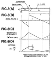
- FIG. 8(A), 8(B), 8(C), and 8(C) A stress diagram of a comparative example is shown in Figures 8(A), 8(B), 8(C), and 8(C) when a dash cross-member 5 is subject to a moment about the axis 30.
- a common boundary between the dash cross-member 5 and a floor 1 includes the axis 30 of the moment.
- the reference character (el) represents a distance along the longitudinal central line 50 from the axis 30 to a rear seat cross member 13 (see Figure 1).
- the reference character Z 1 represents a section modulus of the dash cross-member 5.
- the reference character Z 2 represents a section-modulus of the floor 1.
- Figure 8(B) illustrates the bending moment at various locations along the central longitudinal line. As shown, the bending moment has a negative maximum at the axis 30 (which is also the joining point) and a maximum positive bending moment at the axis 30, thus creating a large stress discontinuity at the axis 30 - the joining point - which is undesirable.
- Figure 8(C) illustrates the magnitude of moment at various locations along the longitudinal central line. The magnitude of the moment is at a maximum at the axis 30 and decreases as the distance from the axis 30 increases.
- Figure 8(D) illustrates the stress variation in a less preferred pattern. According to this less preferred pattern of stress variation, the discontinuity D of stress across the common boundary has a considerably large magnitude, which results in a serious stress concentration at the common boundary.
- FIG. 7(A), 7(B), 7(C), and 7(D) A stress diagram of the first embodiment is shown in Figures 7(A), 7(B), 7(C), and 7(D).
- the first embodiment utilizes the tooth 5DL, 5DR and recess 1RL, 1RR structure of Figures 2-5 to control the stress variation in a preferred pattern as illustrated in Figure 7(B) and 7(C).
- Figures 7(B)-7(D) indicate that the discontinuity D of stress across the common boundary has a satisfactorily small magnitude. This reduction in the magnitude of the discontinuity D has resulted from locating the common boundary within a region where the magnitude of moment is very small and almost zero. Thus, the stress concentration at the common boundary is satisfactorily low.
- the front side members 10L and 10R apply the impact, which induces a moment about the axis 30.
- the axis 30 extends through the curved portion of the sloped lower edge of the toe board section 5A.
- the joints between the teeth 5DL and 5DR and the floor panel portions 1A are at a distance from the axis 30. Accordingly, excessively great concentration of stress on the joints will not take place.
- the dash cross-member 5 has a rigidity that is sufficiently large to support the front side members 10L, 10R such that, as shown in Figure 5, the front side members 10L and 10R collapse telescopically rearward from their forward ends in a predetermined manner, which results in an increased collapsible stroke of the front compartment F ⁇ C. This causes an increase in impact energy absorption.
- curve “a” (solid line) is the impact energy absorption characteristic curve of the first preferred embodiment during a frontal full-lap crash.
- Curve “b” (dashed line) is the impact energy absorption characteristic curve of the comparative example during a frontal full-lap crash.
- the length of each of the teeth 5DL and 5DR is zero and the depth of each of the recesses is zero so that the toe board section 5A has its lower edge directly coupled with the first and second panel portions 1AL and 1AR.
- the dash cross member 5 is collapsed at time Pa.
- the impact energy absorption curve "b the dash cross member 5 is collapsed at time Pb.
- Time Pa is considerably delayed with respect to time Pb, which causes an increase, as indicated by a shadowed area, in the amount of impact energy absorbed by collapsible deformation of the front compartment F ⁇ C.
- This increase in the amount of impact energy due the collapsible deformation of the front compartment F ⁇ C results in a suppressed deformation of the passenger compartment P ⁇ C.
- the tunnel 1B and the side sills 1CL and 1CR project forward beyond the forward edges 70L and 70R of the floor panel portions 1AL and 1AR.
- the forward portion of the floor exhibits a reduction in bending rigidity, which results in a considerable reduction in the level of impact from Gb to Ga.
- the reference characters Gb and Ga indicate levels of impact due to collapsible deformation of the passenger compartments according to the comparative example and the first embodiment, respectively.
- the first embodiment it is easy to design the amount of offset of the common boundary 70L and 70R from the moment axis 30. This results from the arrangement of the teeth 5DL and 5DR fitted into recesses 1RL and 1RR.
- Each tooth 5DL or 5DR and the corresponding recess 1RL or 1RR are rectangular in plan view, which renders them easy to manufacture. Thus, it is easy to provide a sufficiently high level of joining strength between each tooth 5DL or 5DR and the recess defining edge 1DL or 1DR.
- each of the floor panel portions 1AL and 1AR has a forward edge 70L or 70R that extends substantially parallel to the transverse line 52. It is also understood that, at any point on the entire length along the transverse line 52, the first and second teeth 5DL and 5DR extend toward the first and second floor panel portions 1AL and 1AR, respectively, by a common length, thus exhibiting rectangular plan profiles.
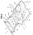
- a second embodiment of the invention will now be described with reference to Figures 9 to 11.
- the second embodiment is substantially the same as the first embodiment except that, in the second embodiment, the first and second teeth 5DL and 5DR and the associated recesses 1RL and 1RR have substantially triangular profiles.
- Each of the forward edges 70L, 70R of the first and second floor panel portions 1AL and 1AR lie obliquely with respect to a transverse line 52.
- the entirety of forward edge 70L, 70R lies behind or rearward of the ends 1CLE, 1CRE, 1BE of the respective side sill 1CL, 1CR and the tunnel 1B.
- the first tooth 5DL extends toward the first floor panel portion 1AL by a length that is proportional to a distance from the left-hand side sill 1CL toward the tunnel 1B along the transverse line 52.
- the second tooth 5DR extends toward the second floor panel portion 1AR by a length that is proportional to a distance from the right-hand side sill 1CR toward the tunnel 1B along the transverse line 52.
- Each of the first and second recess defining edges 1DL, 1DR also includes a laterally extending edge 1BLE, 1BRE, which extend substantially parallel to the longitudinal center line.
- Each laterally extending tunnel edge 1BLE, 1BRE meets the respective forward edge of the floor panel 70L, 70R to form a "V.”
- each of the longitudinally extruded first and second floor panel portions 1AL, 1AR has a length that increases or projects from the tunnel 1B to the forward ends 1CLE, 1CRE of the side sills 1CL and 1CR.
- This arrangement provides for increased impact energy absorption within a limited amount of deformation at the forward portion of the floor 1 during side impact.
- collapsible deformation of the floor 1 is initiated at its connection with the adjacent center pillar 16L or 16R (see Figure 1).
- the collapsible deformation spreads in all directions. Because each extruded floor panel 1AL, 1AR projects toward the forward ends 1CLE, 1CRE of the side sills 1CL, 1CR (i.e., the portion forward portion of the floor 1), the amount of impact energy at the forward portion of the floor 1 increases.
- the transversely extruded tooth 5DL or 5DR prevents inward deformation of the forward portion of the floor 1 beyond the limited amount. Accordingly, a desired deformation mode is provided during side impact.
- the teeth 5DL and 5DR are welded to the respective floor panel portions 1AL, 1AR, respectively, along the forward edges 70L, 70R.
- the teeth 5DL, 5DR are also welded to the structure at the lateral edges 1BLE, 1BRE of the tunnel 1B at the lateral edges 1CLLE, 1CRLE of the side sills 1CL, 1CR.
- the teeth 5DL and 5DR may be welded to the floor panel portions 1AL and 1AR, respectively, through convex curved lines that project toward the floor panel portions 1AL and 1AR to meet various demands on deformation mode.
- the second embodiment utilizes the tooth (5DL, 5DR) and recess (1RL, IRR) structure of Figure 9 to control the stress variation in an even more preferred pattern as illustrated in Figures 25(B) and 25(C).
- Figures 25(B)-25(D) indicate that the discontinuity D of stress across the common boundary is substantially zero due to the triangular shape of the recess and tooth. This reduction in the magnitude of the discontinuity D has resulted from locating the common boundary proportionally from the moment axis rearward to a point that is distant from the moment axis. Thus, the stress concentration at the common boundary is substantially zero.
- a third embodiment will be described with reference to Figure 12.
- This third embodiment is substantially the same as the second preferred embodiment except that a first group of parallel reinforcement bars 20L and a second group of parallel reinforcement bars 20R are provided.
- the first and second groups of reinforcement bars 20L, 20R are attached to the lower side of the floor 1.
- Each reinforcement bar 20L of the first group extends substantially parallel to the longitudinal central line 50 across the forward edge 70L of the left-hand floor panel 1AL.
- Each reinforcement bar 20R of the second group extends substantially parallel to the longitudinal central line 50 across the forward edge 70R of the right-hand floor panel 1AR.
- the forward edges 70L, 70R of the left-hand and right-hand floor panels 1AL, 1AR extend at obliquely from the transverse line 52.
- Each of the reinforcement bars 20L of the first group has a forward end integrated with a common seat 21FL, which is fixedly attached to a base of the first tooth 5DL, and a rearward end formed with an independent seat 21RL, which is fixedly attached to the left-hand floor panel portion 1AL.
- Each of the reinforcement bars 20R of the second group has a forward end integrated with a common seat 21FR, which is fixedly attached to a base of the second tooth 5DR, and a rearward end formed with an independent seat 21RR, which is fixedly attached to the right-hand floor panel portion 1AR.
- Each of the first and second groups of reinforcement bars 20L, 20R is made of a light metal and is die cast, pressed, or extruded.
- Each reinforcement bar 20L, 20R has a cross-sectional area that decreases as a distance from a dash cross-member 5 increases.
- the reinforcement bars 20L, 20R strengthen the connection between the teeth 5DL and 5DR and the associated floor panel portions 1AL and 1AR.
- the sum of cross-sectional areas reduces as the distance from the dash cross-member 5 increases because each reinforcement bar 20L, 20R has a cross-sectional area that decreases as a distance from the dash cross-member 5 increases.
- the setting can be made such that points of inflection of all of the reinforcement bars 20L, 20R are located generally along the forward edges 70L, 70R of the left-hand and right-hand floor panels 1AL, 1AR, which is the arrangement in the third embodiment. Using this arrangement, it is possible to suppress the magnitude of the impact when the passenger compartment collapsibly deforms during a frontal full-lap crash.
- a fourth embodiment of the invention will now be described with reference to Figure 14.
- This fourth embodiment is a modification of the third embodiment.
- a first beam 22FL crosses and interconnects the reinforcement bars 20L of the first or left-hand group
- a second beam 22FR crosses and interconnects the reinforcement bars 20L, 20R of the second or right-hand group.
- the first and second beams 22FL, 22FR lie substantially parallel to the transverse line 52.
- Each end of the first beam 22FL has a seat 23L that is fixedly attached to the left-hand floor panel 1AL to bridge the first recess 1RL.
- Each end of the second beam 22FR has a seat 23R that is fixedly attached to the right-hand floor panel 1AR to bridge the second recess 1RR.
- the first and second beams 22FR, 22FL are rigidly coupled to common seats 21FL, 21R, respectively.
- a plurality of small bars 20SL, 20SR interconnect each of the first and second beams 22FR, 22FL and its respective common seat 21FL, 21FR to increase structural rigidity.
- the beams 22FR, 22FL act to reinforce the floor 1 during a side impact. Adjusting the number of small bars 20SL, 20SR makes it easy to adjust the location of the points of inflections Sp.
- each reinforcement bar 20L, 20R is adjusted by varying the cross-sectional area.
- each reinforcement bar 20 has a flexural rigidity that decreases as a distance from the dash cross member 5 increases.
- Each reinforcement bar 20 has a cross-section that ranges from a predetermined elliptical cross-sectional profile as shown in Figure 15(A) to an upwardly curved partial ring cross-sectional profile as shown in Figure 15(B), both of which are formed by vertical compression.
- the cross-sectional area is constant over the entire length of the reinforcement bar 20.
- FIG. 16 A sixth embodiment of the invention will now be described with reference to Figure 16.
- This sixth embodiment is substantially the same as the third embodiment shown in Figure 12 except the use of a plurality of reinforcement bars 20 as shown in Figures 15(A) and 15(B).
- the sixth embodiment also differs from the previous five embodiments in the use of teeth and recesses having a curved periphery (only one of the tooth-recess combinations is shown). Another difference resides in the use of teeth and the recesses having curved periphery.
- Each reinforcement bar 20 has a flexural rigidity that decreases as a distance from the dash cross-member 5 increases.
- each reinforcement bar 20 has a cross-sectional profile that ranges from an elliptical profile as shown in Figure 15(A) to a ring fragment-like cross-sectional profile as shown in Figure 15(B), both of which are formed using vertical compression.
- the cross-sectional area is constant over the entire length of each reinforcement bar 20.
- the reinforcement bar 20 has the cross-sectional profile as shown in Figure 15(A).
- the reinforcement bar 20 has the cross-sectional profile as shown in Figure 15(B).
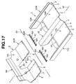
- a seventh embodiment of the invention will now be described with reference to Figures 17 to 24. Comparing Figure 17 with Figure 4 will reveal that the seventh embodiment is substantially the same as the first embodiment. However, the seventh embodiment is different from the first embodiment in the manner of joining the first and second teeth 5DL and 5DR of the dash cross-member 5 with the forward edges 70L, 70R of the left-hand and right-hand floor panels 1AL, 1AR.
- a first joint 40L is used to connect the first tooth 5DL to the left-hand floor panel 1AL and a second joint 40R is used to connect the second tooth 5DR to the right-hand floor panel 1AR prior to welding.
- the first and second joints 40L, 40R are identical.
- each of the first and second joints 40L, 40R is an extruded part constructed from a light metal, such as an aluminum alloy.
- the first and second joints 40L, 40R are extruded in the same direction as the dash cross-member 5.
- each joint 40L, 40R has a coupling half 46 and an insert 42.
- Each of the teeth 5DL and 5DR of the dash cross-member 5 has a coupling half 47 that is adapted to be in locking engagement with the coupling half 46 of the respective mating joint 40.
- each floor panel 1AL, 1AR is connected to the tunnel 1B and its respective side sill 1CL, 1CR using couplings 200.
- each of the floor panels 1AL, 1AR has a plurality of channels S, which are formed during the extrusion process, that are separated by partitions 4. These channels S are open at forward edges 70L, 70R of the floor panels 1AL, 1AR.
- Each of the joints 40L, 40R has an insert 42.
- Each insert 42 is inserted into the extrusion channels S of the floor panels 1AL, 1AR, which prevents the floor panels 1AL, 1AR from warping when welded. Because the floor panels 1AL, 1AC have extrusion channels S that are separated by reinforcement walls 4, the insert 42 is divided by spaced slits 42c into segments.
- Each insert 42 has two parallel spaced walls 42a that are interconnected by a tapered projection 42b.
- the distance between the two spaced walls 42a is substantially the same as the distance between the two spaced walls 2 and 3 that define the corresponding channel S.
- each joint has a stop 43 that extends substantially vertically and that abuts the spaced walls 2 and 3 of the floor panels 1AL, 1AR.
- Each of the parallel spaced walls 42a of the projection 42 extend from the stop 43 at a substantially right angle.
- the stop 43 is spaced from another vertical wall 48.
- the stop 43 and the vertical wall 48 are interconnected by two spaced horizontal and substantially parallel upper and lower walls 44 and 45.
- the upper and lower horizontal wall 44 and 45 extend in parallel from the vertical wall on which the stop 43 is formed, but the lower wall 45 extends further than the upper wall 44 does.
- the lower wall 45 extends beyond the vertical wall 48.
- an appropriate welding technique such as laser welding or MIG welding, is used to weld the joint 40L or 40R to the respective floor panel portion 1AL or 1AR.
- the coupling half 46 of each joint 40L, 40R has a cavity 46U.
- the coupling half 47 of each tooth 5DL and 5DR has a projection 47U that is inserted into the cavity 46U.
- the cavity 46U and the respective projection 47U serve as a center about which the dash cross-member 5 can pivot toward a predetermined position relative to the floor panel portions 1AL and 1AR of the floor 1.
- the coupling half 46 of each joint 40 has a latch receiving cavity 46L.
- the coupling half 47 of each tooth 5DL or 5DR has a latch 47L that is fitted, by snap action, into the latch receiving cavity 46U, to hold the dash cross-member 5 in the predetermined position. .
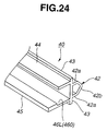
- a modified joint 40A is shown in Figure 24.
- this modified joint 40A there is no cavity 46U.
- the coupling half 460 still has the latch receiving cavity 46L.
Landscapes
- Engineering & Computer Science (AREA)
- Chemical & Material Sciences (AREA)
- Combustion & Propulsion (AREA)
- Transportation (AREA)
- Mechanical Engineering (AREA)
- Architecture (AREA)
- Structural Engineering (AREA)
- Body Structure For Vehicles (AREA)
Abstract
Description
- The present invention relates to a vehicle body structure and, more particularly, to a vehicle body structure having decreased weight and increased strength.
- JP-A 9-99870 discloses a vehicle floor constructed of a plurality of aluminum alloy extruded parts that have been extruded in a direction parallel to a longitudinal central line of a vehicle. Hollow extruded materials are arranged in the longitudinal direction of a body and welded together to form the floor section of the body frame of an automobile. The extruded materials are molded with two kinds of dies so that the extruded materials have symmetrical cross-sectional shapes respectively. They are inverted and symmetrically arranged across another extruded material and are welded to form the floor section. The types of the extruded materials can be decreased, molding and machining facilities can be miniaturized, and the manufacturing cost can be reduced.
- There is a need for a vehicle body structure having a reduced stress discontinuity at a point where the structural members are connected.
- There is also a need for a vehicle body structure in which a moment arm caused by deformation of the dash panel is reduced.
- There is a further need for a vehicle body structure having increased strength with decreased weight.
- These and other needs may be satisfied by an embodiment of the invention which provides a vehicle body structure for a vehicle having a longitudinal centerline and a transverse line that crosses the longitudinal centerline. The vehicle body structure comprises an extruded cross member having at least one tooth and an extruded floor. The extruded floor is comprised of a plurality of structural members having ends that contact the cross member. The extruded floor is also comprised of at least one floor panel portion disposed between adjacent ones of the plurality of structural members. Each of the floor panel portions has an edge that is at least partially recessed from the ends of the adjacent structural members to form a recess. Each recess receives a corresponding one of the at least one tooth.
- Additional advantages and novel features of the invention will be set forth, in part, in the following description, and, in part, will be apparent to those skilled in the art after examining the following or by practising the invention. The advantages of the invention may be realized and attained via the instrumentalities and combinations particularly pointed out in the appended claims.
- Preferred embodiments of the invention will be described with reference to the attached drawings, which are incorporated in and constitute a part of the specification, in which:
- Figure 1 is a fragmentary perspective view of a vehicle body implementing the present invention;
- Figure 2 is a fragmentary perspective view of a vehicle body structure according to a first embodiment of the invention;
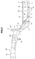
- Figure 3 is a fragmentary side view of the vehicle body structure along line III-III in Figure 2;
- Figure 4 is an exploded view of the vehicle body structure of Figure 2;
- Figure 5 illustrates the vehicle body structure after a frontal full-lap crash of the vehicle;
- Figure 6 illustrates energy absorption during a frontal full-lap crash;
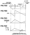
- Figure 7(A) is a schematic illustration of the first embodiment, Figure 7(B) is a bending moment diagram illustrating the bending moment along the first embodiment of Figure 7(A), Figure 7(C) is a diagram illustrating the variation of the magnitude of moment about an axis below a toe board section of a cross-member against varying distance, and Figure 7(D) is a stress diagram illustrating the variation of stress to which the structure of Figure 7(A) is subject against varying distance;
- Figure 8(A) is a schematic illustration of a comparative example where a common boundary between a cross-member and a floor includes the axis of the moment, Figure 8(B) is the same diagram as Figure 7(B) of the example of Figure 8(A), Figure 8(C) is the same diagram as Figure 7(C) of the example of Figure 8(A), and Figure 8(D) is a stress diagram illustrating the variation of stress to which the structure of Figure 8(A) is subject against varying distance;
- Figure 9 is a view similar to Figure 2 illustrating a second embodiment of the present invention;
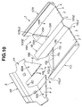
- Figure 10 an exploded view of the vehicle body structure of Figure 9;
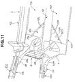
- Figure 11 is a fragmentary bottom perspective view of the vehicle body structure of Figure 9;
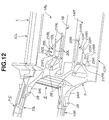
- Figure 12 is a view similar to Figure 11 illustrating a third embodiment of the present invention;
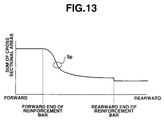
- Figure 13 is graphical representation of the variation of the cross-sectional area of each of the reinforcement bars versus the distance from a cross-member;
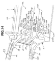
- Figure 14 is a view similar to Figure 11 illustrating a fourth embodiment of the present invention;
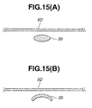
- Figures 15(A) and 15(B) illustrate cross-sectional profiles of each of the reinforcement bars at its forward end and at its rearward end, illustrating a fifth embodiment of the present invention;
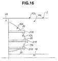
- Figure 16 is a schematic view of a bottom view of a vehicle body structure illustrating a sixth embodiment of the present invention;
- Figure 17 is an exploded view of a vehicle body structure, illustrating a seventh embodiment of the present invention;
- Figure 18 is an exploded view showing a portion of a joint and a portion of a floor panel portion of a floor;
- Figure 19 is section taken through the line XIX-XIX in Figure 18;
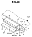
- Figure 20 is a fragmentary perspective view showing the joint inserted into the floor panel portion of the floor;
- Figure 21 is a section similar to that of Figure 16 showing a cross-member held in a predetermined position with respect to the joint;
- Figure 22 is an exploded view of a floor with a joint, illustrating an eighth embodiment of the present invention;
- Figure 23 is a fragmentary perspective view of the floor with joints inserted into the floor panel portions;
- Figure 24 is a fragmentary perspective view of a modification of a joint; and
- Figure 25(A) is a schematic illustration of the second embodiment, Figure 25(B) is a bending moment diagram illustrating the bending moment along the second embodiment of Figure 25(A), Figure 25(C) is a diagram illustrating the variation of the magnitude of moment about an axis below a toe board section of the cross-member against varying distance, and Figure 25(D) is a stress diagram illustrating the variation of stress to which the structure of Figure 25(A) is subject against varying distance;
-
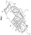
- Referring now to the drawings, and initially to Figure 1, there will be seen a vehicle superstructure or a vehicle body structure having a cabin or passenger compartment P·C, a front compartment F·C, and a rear compartment R·C. In each of the embodiments of the present invention, the invention is implemented in a forward portion of the vehicle, which includes a cross member or dash cross-member and a floor. The present invention is equally applicable to a rearward portion of the vehicle, which includes a cross-member or rear cross-member and a floor.
- A first embodiment of the invention will be described with reference to Figures 1 through 6. Referring to Figures 1 and 2, the vehicle has a longitudinal
central line 50 and atransverse line 52, which intersects the longitudinalcentral line 50 at a substantially right angle. The vehicle body structure comprises afloor 1 and adash cross-member 5. Thefloor 1 extends rearward from thedash cross-member 5 substantially parallel to the longitudinalcentral line 50. At its rear end, thefloor 1 is connected to arear seat cross-member 13. Connected to and extending rearward from therear seat cross-member 5 is arear floor panel 14. - The vehicle includes a left-hand
front pillar 15L, a left-hand center pillar 16L, a left-handrear pillar 17L, a left-handrear fender 19L, a right-hand front pillar 15R, a right-hand center pillar 16R, a right-hand rear pillar (not shown), a right-handrear fender 19R, and aroof panel 18. In the usual manner, thedash cross-member 5, thefloor 1, thefront pillars center pillars rear pillars 17L, the rearseat cross member 13, therear floor panel 14, and theroof panel 18 at least partially define the passenger compartment P·C. - The
floor 1 is formed by extruding a light metal material, such as an aluminum alloy, in a first direction, which is substantially parallel to the longitudinalcentral line 50. As best seen in Figure 2, thefloor 1 has two spaced walls, namely anupper wall 2 and alower wall 3, and partitions orreinforcement walls 4 between the upper andlower walls partitions 4 and the upper andlower walls walls central line 50. Thepartitions 4 enhance the structural rigidity of thefloor 1. - The
floor 1 includes at least portions of a plurality of floor structural members, which extend rearward from thedash cross-member 5 substantially parallel to the longitudinalcentral line 50. The plurality of structural members include acentral tunnel 1B and a first or left-hand side sill 1CL that is spaced from thetunnel 1B in a first or leftward direction, which is substantially parallel to thetransverse line 52. The plurality of structural members further includes a second or right-hand side sill 1CR that is spaced from thetunnel 1B in a second or rightward direction, which is substantially parallel to thetransverse line 52. Thefloor 1 includes a first or left-hand floor panel portion 1AL that extends between thetunnel 1B and the first side sill 1CL, and a second or right-hand floor panel portion 1AR that extends between thetunnel 1B and the second side sill 1CR. - As shown in Figures 2 and 3, the
dash cross-member 5 has atoe board section 5A and a vertically extendingwall section 5B that extends from thetoe board section 5A. Similar to thefloor 1, thedash cross-member 5 is formed by extruding an aluminum alloy in a direction that is substantially parallel to thetransverse line 52. Thedash cross-member 5 has two spaced walls, namely aninner wall 6 and anouter wall 7, andpartitions 8 between the two spacedwalls partitions 8 and the two spacedwalls walls transverse line 52. Thedash cross-member 5 has the same cross sectional profile over its entire length along thetransverse line 52. Thepartitions 8 enhance the rigidity of thedash cross-member 5. - The
dash cross-member 5 has acutout 5C that receives thetunnel 1B of thefloor 1. Thiscutout 5C is cut inwardly into thetoe board section 5A at a midpoint between opposite ends of thetoe board section 5A. Areinforcement structure 9 extends over theouter wall 7 from the vertically extendingwall section 5B to thetoe board section 5A. Thereinforcement structure 9 has two arms, namely a left-hand arm 9AL and a right-hand arm 9AR, that extend in a lengthwise forward direction of the vehicle substantially parallel to the longitudinalcentral line 50. The two arms 9AL and 9AR are spaced from each other in the transverse direction of the vehicle and fixedly support front left-hand and right-hand side members - As shown in Figures 1 and 2, the front compartment is at least partially defined by a
first cross-member 11 and abumper armature 12, which connect the forward end portions of thefront side members front side members housings - With its
cutout 5C coupled to thetunnel 1B, thetoe board section 5A of thedash cross-member 5 is brought into abutting contact with the forward ends of the side sills 1CL and 1CR. Using an appropriate welding technique, such as laser welding or metal inert gas (MIG) welding, the joints between thetoe board section 5A and the forward ends of the side sills 1CL and 1CR are welded, and the joint between thecutout 5C and thetunnel 1B is welded. Of course, any other appropriate attachment technique may be used instead of welding. - As shown in Figure 2, the
floor 1 includes a first or left-hand floor panel portion 1AL that is disposed between thetunnel 1B and the first side sill 1CL. Thefloor 1 also includes a second or right-hand floor panel portion 1AR that is disposed between thetunnel 1B and the second side sill 1CR. - The
tunnel 1B and left and right side sills 1CL and 1CR, respectively, have forward edges or ends 1BE, 1CLE, and 1CRE, respectively. The forward ends 1BE, 1CLE, and 1CRE contact thedash cross-member 5 and are welded to thedash cross-member 5. The left-hand floor panel portion 1AL has aforward edge 70L that is recessed from the tunnel forward edge 1BE and the left-hand side sill forward edge 1CLE to define a first recess 1RL (Figure 4). The right-hand floor panel portion 1AR has aforward edge 70R that is recessed from the tunnel forward edge 1BE and the right-hand side sill forward edges 1CRE to form a recess 1RR (Figure 4). - The left-hand side sill 1CL has a lateral edge 1CLLE that extends rearward from its forward end 1CLE. The right-hand side sill 1CR has a lateral edge 1CRLE that extends rearward from its forward end 1CRE. The
tunnel 1B has opposing lateral edges 1BLE and 1BRE that extend rearward from its forward end 1BE. The left-hand side sill lateral edge 1CLLE, the left-hand floor panel forward edge 70L and the tunnel lateral edge 1BLE define a first or left recess defining edge 1DL. The right-hand side sill lateral edge 1CRLE, the tunnel lateral edge 1BRE, and the right-hand floor panel forward edge 70R define a second or right-hand recess defining edge 1DR. - The
cross-member 5 includes a first tooth 5DL that extends integrally from thetoe board section 5A. The first tooth 5DL is coupled to the first or left-hand recess 1RL and is connected to thefloor 1 along the first recess defining edge 1DL. Thecross-member 5 also includes a second tooth 5DR that extends integrally from thetoe board section 5A. The second tooth 5DR is coupled to the second or right-hand recess 1RR and is connected to thefloor 1 along the second recess defining edge 1DR. In the first embodiment, the first and second recesses are rectangular. - The first and second teeth 5DL and 5DR are each extruded concurrently with the other portions of the
cross-member 5. The first and second teeth 5DL and 5DR have the same cross-sectional profile over their entire lengths in the transverse direction and include a plurality of channels between the inner andouter walls partitions 8. Thepartitions 8 interconnect the inner andouter walls tunnel 1B, the floor panel portions 1AL and 1AR, and the side sills 1CL and 1CR. - In this first embodiment, each of the first and second teeth 5DL and 5DR has a
socket 5E into which theforward edge - With their forward ends 1CLE and 1CRE in abutting contact with the
toe board section 5A, each of the side sills 1CL and 1CR has its inner lower portion lying over the side of one of the first and second teeth 5DL and 5DR prior to welding. Accordingly, each of the side sills 1CL, 1CR has an elongated flat surface area having a width equal to the thickness of the respective one of the first and second teeth 5DL and 5DR. - The preceding description clearly indicates that the
dash cross member 5 and thefloor 1 share a common boundary and are joined to each other. During a frontal full-lap crash of the vehicle, thedash cross-member 5 is subject to a moment about anaxis 30, which lies substantially parallel to thetransverse line 52. In a region near thisaxis 30 of moment, the forward ends of the side sills 1CLE and 1CRE are in abutting engagement with thetoe board section 5A of thedash cross-member 5. Thetunnel 1B extends through thecutout 5C. According to the preceding description, thecross-member 5 and each of the floor panel portions 1AL and 1AR have a common boundary at 70L or 70R and are joined to each other such that the common boundary is not disposed within a region near theaxis 30 of moment. In order to suppress variation of stress across the common boundary when thecross-member 5 is subject to a moment about theaxis 30, thecross-member 5 includes an integral portion in the form of teeth 5DL and 5DR. The teeth 5DL and 5DR extend rearward substantially parallel to the longitudinalcentral line 50 and have a periphery. Each of the floor panel portions 1AL and 1AR has aforward edge tunnel 1B has opposing lateral edges 1BLE and 1BRE and the side sills each have rearward extending lateral edges 1CLLE and 1CRLE that, together with theforward edges - A stress diagram of a comparative example is shown in Figures 8(A), 8(B), 8(C), and 8(C) when a
dash cross-member 5 is subject to a moment about theaxis 30. In the comparative example, a common boundary between thedash cross-member 5 and afloor 1 includes theaxis 30 of the moment. In Figure 8(A), the reference character(el) represents a distance along the longitudinal
central line 50 from theaxis 30 to a rear seat cross member 13 (see Figure 1). The reference character Z1 represents a section modulus of thedash cross-member 5. The reference character Z2 represents a section-modulus of thefloor 1. It is seen that there occurs a change in rigidity across the common boundary so that the section modulus is subject to a change across the common boundary. Figure 8(B) illustrates the bending moment at various locations along the central longitudinal line. As shown, the bending moment has a negative maximum at the axis 30 (which is also the joining point) and a maximum positive bending moment at theaxis 30, thus creating a large stress discontinuity at the axis 30 - the joining point - which is undesirable. Figure 8(C) illustrates the magnitude of moment at various locations along the longitudinal central line. The magnitude of the moment is at a maximum at theaxis 30 and decreases as the distance from theaxis 30 increases. Figure 8(D) illustrates the stress variation in a less preferred pattern. According to this less preferred pattern of stress variation, the discontinuity D of stress across the common boundary has a considerably large magnitude, which results in a serious stress concentration at the common boundary. - A stress diagram of the first embodiment is shown in Figures 7(A), 7(B), 7(C), and 7(D). The first embodiment utilizes the tooth 5DL, 5DR and recess 1RL, 1RR structure of Figures 2-5 to control the stress variation in a preferred pattern as illustrated in Figure 7(B) and 7(C). Figures 7(B)-7(D) indicate that the discontinuity D of stress across the common boundary has a satisfactorily small magnitude. This reduction in the magnitude of the discontinuity D has resulted from locating the common boundary within a region where the magnitude of moment is very small and almost zero. Thus, the stress concentration at the common boundary is satisfactorily low.
- During frontal full-lap crash, the
front side members axis 30. Theaxis 30 extends through the curved portion of the sloped lower edge of thetoe board section 5A. The joints between the teeth 5DL and 5DR and the floor panel portions 1A are at a distance from theaxis 30. Accordingly, excessively great concentration of stress on the joints will not take place. - The
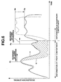
dash cross-member 5 has a rigidity that is sufficiently large to support thefront side members front side members - Referring to Figure 6, curve "a" (solid line) is the impact energy absorption characteristic curve of the first preferred embodiment during a frontal full-lap crash. Curve "b" (dashed line) is the impact energy absorption characteristic curve of the comparative example during a frontal full-lap crash. According to the comparative example, the length of each of the teeth 5DL and 5DR is zero and the depth of each of the recesses is zero so that the
toe board section 5A has its lower edge directly coupled with the first and second panel portions 1AL and 1AR. In Figure 6, according to the impact energy absorption curve "a " thedash cross member 5 is collapsed at time Pa. According to the impact energy absorption curve "b " thedash cross member 5 is collapsed at time Pb. Time Pa is considerably delayed with respect to time Pb, which causes an increase, as indicated by a shadowed area, in the amount of impact energy absorbed by collapsible deformation of the front compartment F·C. This increase in the amount of impact energy due the collapsible deformation of the front compartment F·C results in a suppressed deformation of the passenger compartment P·C. - According to the first embodiment, the
tunnel 1B and the side sills 1CL and 1CR project forward beyond theforward edges - According to the first embodiment, it is easy to design the amount of offset of the
common boundary moment axis 30. This results from the arrangement of the teeth 5DL and 5DR fitted into recesses 1RL and 1RR. - Each tooth 5DL or 5DR and the corresponding recess 1RL or 1RR are rectangular in plan view, which renders them easy to manufacture. Thus, it is easy to provide a sufficiently high level of joining strength between each tooth 5DL or 5DR and the recess defining edge 1DL or 1DR.
- From the preceding description of the first embodiment, it is also very apparent that each of the floor panel portions 1AL and 1AR has a
forward edge transverse line 52. It is also understood that, at any point on the entire length along thetransverse line 52, the first and second teeth 5DL and 5DR extend toward the first and second floor panel portions 1AL and 1AR, respectively, by a common length, thus exhibiting rectangular plan profiles. - A second embodiment of the invention will now be described with reference to Figures 9 to 11. The second embodiment is substantially the same as the first embodiment except that, in the second embodiment, the first and second teeth 5DL and 5DR and the associated recesses 1RL and 1RR have substantially triangular profiles. Each of the
forward edges transverse line 52. As shown in Figure 9, the entirety offorward edge tunnel 1B. - The first tooth 5DL extends toward the first floor panel portion 1AL by a length that is proportional to a distance from the left-hand side sill 1CL toward the
tunnel 1B along thetransverse line 52. The second tooth 5DR extends toward the second floor panel portion 1AR by a length that is proportional to a distance from the right-hand side sill 1CR toward thetunnel 1B along thetransverse line 52. Each of the first and second recess defining edges 1DL, 1DR also includes a laterally extending edge 1BLE, 1BRE, which extend substantially parallel to the longitudinal center line. Each laterally extending tunnel edge 1BLE, 1BRE meets the respective forward edge of thefloor panel - According to the second embodiment, each of the longitudinally extruded first and second floor panel portions 1AL, 1AR has a length that increases or projects from the
tunnel 1B to the forward ends 1CLE, 1CRE of the side sills 1CL and 1CR. This arrangement provides for increased impact energy absorption within a limited amount of deformation at the forward portion of thefloor 1 during side impact. - During side impact, collapsible deformation of the
floor 1 is initiated at its connection with theadjacent center pillar floor 1 increases. The transversely extruded tooth 5DL or 5DR prevents inward deformation of the forward portion of thefloor 1 beyond the limited amount. Accordingly, a desired deformation mode is provided during side impact. - In the second embodiment, the teeth 5DL and 5DR are welded to the respective floor panel portions 1AL, 1AR, respectively, along the forward edges 70L, 70R. The teeth 5DL, 5DR are also welded to the structure at the lateral edges 1BLE, 1BRE of the
tunnel 1B at the lateral edges 1CLLE, 1CRLE of the side sills 1CL, 1CR. If desired, the teeth 5DL and 5DR may be welded to the floor panel portions 1AL and 1AR, respectively, through convex curved lines that project toward the floor panel portions 1AL and 1AR to meet various demands on deformation mode. - A stress diagram of the second embodiment is shown in Figures 25(A), 25(B), 25(C), and 25(D). The second embodiment utilizes the tooth (5DL, 5DR) and recess (1RL, IRR) structure of Figure 9 to control the stress variation in an even more preferred pattern as illustrated in Figures 25(B) and 25(C). Figures 25(B)-25(D) indicate that the discontinuity D of stress across the common boundary is substantially zero due to the triangular shape of the recess and tooth. This reduction in the magnitude of the discontinuity D has resulted from locating the common boundary proportionally from the moment axis rearward to a point that is distant from the moment axis. Thus, the stress concentration at the common boundary is substantially zero.
- A third embodiment will be described with reference to Figure 12. This third embodiment is substantially the same as the second preferred embodiment except that a first group of
parallel reinforcement bars 20L and a second group of parallel reinforcement bars 20R are provided. The first and second groups of reinforcement bars 20L, 20R are attached to the lower side of thefloor 1. - Each
reinforcement bar 20L of the first group extends substantially parallel to the longitudinalcentral line 50 across theforward edge 70L of the left-hand floor panel 1AL. Eachreinforcement bar 20R of the second group extends substantially parallel to the longitudinalcentral line 50 across theforward edge 70R of the right-hand floor panel 1AR. In the third embodiment, as is true in the second embodiment, the forward edges 70L, 70R of the left-hand and right-hand floor panels 1AL, 1AR extend at obliquely from thetransverse line 52. - Each of the reinforcement bars 20L of the first group has a forward end integrated with a common seat 21FL, which is fixedly attached to a base of the first tooth 5DL, and a rearward end formed with an independent seat 21RL, which is fixedly attached to the left-hand floor panel portion 1AL.
- Each of the reinforcement bars 20R of the second group has a forward end integrated with a common seat 21FR, which is fixedly attached to a base of the second tooth 5DR, and a rearward end formed with an independent seat 21RR, which is fixedly attached to the right-hand floor panel portion 1AR.
- Each of the first and second groups of reinforcement bars 20L, 20R is made of a light metal and is die cast, pressed, or extruded. Each
reinforcement bar dash cross-member 5 increases. - According to the third embodiment, the reinforcement bars 20L, 20R strengthen the connection between the teeth 5DL and 5DR and the associated floor panel portions 1AL and 1AR.
- Let us now consider two hypothetical parallel vertical (HPV) planes having interposed therebetween a selected one of the reinforcement bars 20L, 20R. At each point along the selected bar, a sum of the cross-sectional area of the reinforcement bar and a cross-sectional area of that portion of a tooth which is disposed between the HPV planes or a cross sectional area of that portion of a floor panel portion which is disposed between the HPV planes is calculated. Figure 13 is the plotting of the calculated results of the sum of the cross-sectional areas. The curve shown in Figure 13 has an inflection point Sp. As shown by the curve in Figure 13, the sum of cross-sectional areas reduces as the distance from the
dash cross-member 5 increases because eachreinforcement bar dash cross-member 5 increases. As a result, it is possible to set a point of inflection Sp anywhere within a region ranging from 20 % to 50 % in length from the forward end. Accordingly, the setting can be made such that points of inflection of all of the reinforcement bars 20L, 20R are located generally along the forward edges 70L, 70R of the left-hand and right-hand floor panels 1AL, 1AR, which is the arrangement in the third embodiment. Using this arrangement, it is possible to suppress the magnitude of the impact when the passenger compartment collapsibly deforms during a frontal full-lap crash. - A fourth embodiment of the invention will now be described with reference to Figure 14. This fourth embodiment is a modification of the third embodiment. In contrast to the reinforcement bars 20L, 20R of the third embodiment, a first beam 22FL crosses and interconnects the reinforcement bars 20L of the first or left-hand group, and a second beam 22FR crosses and interconnects the reinforcement bars 20L, 20R of the second or right-hand group. The first and second beams 22FL, 22FR lie substantially parallel to the
transverse line 52. Each end of the first beam 22FL has aseat 23L that is fixedly attached to the left-hand floor panel 1AL to bridge the first recess 1RL. Each end of the second beam 22FR has aseat 23R that is fixedly attached to the right-hand floor panel 1AR to bridge the second recess 1RR. - The first and second beams 22FR, 22FL are rigidly coupled to common seats 21FL, 21R, respectively. A plurality of small bars 20SL, 20SR interconnect each of the first and second beams 22FR, 22FL and its respective common seat 21FL, 21FR to increase structural rigidity.
- The beams 22FR, 22FL act to reinforce the
floor 1 during a side impact. Adjusting the number of small bars 20SL, 20SR makes it easy to adjust the location of the points of inflections Sp. - A fifth embodiment of the invention will now be described with reference to Figures 15(A) and 15(B). In the third and fourth embodiments, the reinforcement characteristic of each
reinforcement bar reinforcement bar 20 has a flexural rigidity that decreases as a distance from thedash cross member 5 increases. Eachreinforcement bar 20 has a cross-section that ranges from a predetermined elliptical cross-sectional profile as shown in Figure 15(A) to an upwardly curved partial ring cross-sectional profile as shown in Figure 15(B), both of which are formed by vertical compression. The cross-sectional area is constant over the entire length of thereinforcement bar 20. - A sixth embodiment of the invention will now be described with reference to Figure 16. This sixth embodiment is substantially the same as the third embodiment shown in Figure 12 except the use of a plurality of reinforcement bars 20 as shown in Figures 15(A) and 15(B). The sixth embodiment also differs from the previous five embodiments in the use of teeth and recesses having a curved periphery (only one of the tooth-recess combinations is shown). Another difference resides in the use of teeth and the recesses having curved periphery.
- Each
reinforcement bar 20 has a flexural rigidity that decreases as a distance from thedash cross-member 5 increases. In this example, eachreinforcement bar 20 has a cross-sectional profile that ranges from an elliptical profile as shown in Figure 15(A) to a ring fragment-like cross-sectional profile as shown in Figure 15(B), both of which are formed using vertical compression. The cross-sectional area is constant over the entire length of eachreinforcement bar 20. At its forward end, thereinforcement bar 20 has the cross-sectional profile as shown in Figure 15(A). At its rear end, thereinforcement bar 20 has the cross-sectional profile as shown in Figure 15(B). - A seventh embodiment of the invention will now be described with reference to Figures 17 to 24. Comparing Figure 17 with Figure 4 will reveal that the seventh embodiment is substantially the same as the first embodiment. However, the seventh embodiment is different from the first embodiment in the manner of joining the first and second teeth 5DL and 5DR of the
dash cross-member 5 with theforward edges - A first joint 40L is used to connect the first tooth 5DL to the left-hand floor panel 1AL and a second joint 40R is used to connect the second tooth 5DR to the right-hand floor panel 1AR prior to welding. In this embodiment, the first and
second joints - As best seen in Figure 18, each of the first and
second joints second joints dash cross-member 5. As best seen in Figure 21, each joint 40L, 40R has acoupling half 46 and aninsert 42. Each of the teeth 5DL and 5DR of thedash cross-member 5 has acoupling half 47 that is adapted to be in locking engagement with thecoupling half 46 of the respective mating joint 40. - Referring to Figures 22 and 23, each floor panel 1AL, 1AR is connected to the
tunnel 1B and its respective side sill 1CL,1CR using couplings 200. - As shown in Figures 19-21, the
joints - More specifically, as mentioned above, each of the floor panels 1AL, 1AR has a plurality of channels S, which are formed during the extrusion process, that are separated by
partitions 4. These channels S are open atforward edges - Each of the
joints insert 42. Eachinsert 42 is inserted into the extrusion channels S of the floor panels 1AL, 1AR, which prevents the floor panels 1AL, 1AR from warping when welded. Because the floor panels 1AL, 1AC have extrusion channels S that are separated byreinforcement walls 4, theinsert 42 is divided by spacedslits 42c into segments. - Each
insert 42 has two parallel spacedwalls 42a that are interconnected by a taperedprojection 42b. The distance between the two spacedwalls 42a is substantially the same as the distance between the two spacedwalls projection 42 is inserted into the channel S, each joint has astop 43 that extends substantially vertically and that abuts the spacedwalls walls 42a of theprojection 42 extend from thestop 43 at a substantially right angle. Thestop 43 is spaced from anothervertical wall 48. Thestop 43 and thevertical wall 48 are interconnected by two spaced horizontal and substantially parallel upper andlower walls horizontal wall stop 43 is formed, but thelower wall 45 extends further than theupper wall 44 does. Thelower wall 45 extends beyond thevertical wall 48. - Once the
projection 42 is inserted into the respective channels S of the floor panel portion 1AL or 1AR, an appropriate welding technique, such as laser welding or MIG welding, is used to weld the joint 40L or 40R to the respective floor panel portion 1AL or 1AR. - As best seen in Figures 18 and 19, the
coupling half 46 of each joint 40L, 40R has acavity 46U. As best seen in Figure 21, thecoupling half 47 of each tooth 5DL and 5DR has aprojection 47U that is inserted into thecavity 46U. Thecavity 46U and therespective projection 47U serve as a center about which thedash cross-member 5 can pivot toward a predetermined position relative to the floor panel portions 1AL and 1AR of thefloor 1. Thecoupling half 46 of each joint 40 has alatch receiving cavity 46L. As best seen in Figure 21, thecoupling half 47 of each tooth 5DL or 5DR has alatch 47L that is fitted, by snap action, into thelatch receiving cavity 46U, to hold thedash cross-member 5 in the predetermined position. . - A modified joint 40A is shown in Figure 24. In this modified joint 40A, there is no
cavity 46U. Thecoupling half 460 still has thelatch receiving cavity 46L. - Although the invention has been described with reference to only a limited number of embodiments, the scope of invention is not limited thereto. That is to say, various modifications and variations of the embodiments described above will be evident to those skilled in the art after reading the above.
- The contents of disclosure of Japanese Patent Applications No. 11-297413, filed October 19, 1999, and No. 11-297438, filed October 19, 1999, are hereby incorporated by reference in their entireties.
Claims (31)
- A vehicle body structure comprising:an extruded cross-member having at least one tooth (5DR;5DL); andan extruded floor (1) including:a plurality of structural members (1B, 1CR, 1CL) having ends contacting the cross-member (5); andat least one floor panel portion (1AR;1AL) disposed between adjacent ones (1B,1CR;1B,1CL) of the structural members (1B,1CR,1CL) and having an edge (70R;70L) at least partially recessed from the ends of the structural members to form a recess (1RR;1RL) that receives the tooth (5DR;5DL).
- A vehicle body structure as claimed in claim 1, wherein the plurality of structural members comprises a tunnel (1B) and at least one side sill (1CR;LCL) spaced from the tunnel.
- A vehicle body structure as claimed in claim 1 or 2, wherein the cross-member (5) comprises a toe board section (5A) extending at an angle from a wall section (5B).
- A vehicle body structure as claimed in claim 3, wherein the tooth (5DR;5DL) and the toe board section (5A) are a monolithic piece.
- A vehicle body structure as claimed in any preceding claim, wherein the at least one tooth (5DR;5DL) has a uniform cross-section along the transverse direction of the vehicle body structure.
- A vehicle body structure as claimed in any preceding claim, wherein each recess (1RR;1RL) and tooth (5DR;5DL) is substantially rectangular or substantially triangular in shape.
- A vehicle body structure as claimed in any preceding claim, wherein substantially zero stress discontinuity arises during an impact.
- A vehicle body structure as claimed in any preceding claim, further comprising two side members (10R, 10L) connected to the cross member (5) substantially in parallel to each other.
- A vehicle body structure as claimed in any preceding claim, further comprising a plurality of reinforcement members (20R;20L) connected at a first end to the cross-member (5), in particular to the toe board section (5A) and at a second end to the floor panel portion (1AR;1AL).
- A vehicle body structure as claimed in claim 9, wherein each reinforcement member (20R;20L) has a flexural rigidity that decreases from the cross-member (5), in particular from the toe board section (5A) to the floor panel portion (1AR;1AL).
- A vehicle body structure as claimed in claim 9 or 10, wherein each reinforcement member (20R;20L) has a substantially uniform cross-sectional area and a cross-sectional profile that is substantially elliptical at one end and arcuate at the other end.
- A vehicle body structure as claimed in claim 3, including:a first group of reinforcement members (20L) extending substantially longitudinally and being connected at one end to the toe board section (5A) and at the other end to a first floor panel (1AL) disposed between the tunnel (1B) and a first side sill (1CL); anda second group of reinforcement members (20R) extending substantially longitudinally and being connected at one end to the toe board section (5A) and at the other end to a second floor panel (1AR) disposed between the tunnel (1B) and a second side sill (1CR);
wherein each reinforcement member (20L;20R) preferably has a cross-sectional area that decreases from the toe board section (5A) to its respective floor panel (1AL;1AR). - A vehicle body structure as claimed in claim 12, further comprising:a first beam (22FL) extending substantially transversely and interconnecting the first group of reinforcement members (20L); anda second beam (22FR) extending substantially transversely and interconnecting the second group of reinforcement members (20R).
- A vehicle body structure as claimed in claim 2, including:a first joint (40L) connecting a first tooth (5DL) to a first floor panel (1AL) disposed between the tunnel (1B) and a first side sill (1CL) and having a coupling portion (46) and projecting portions (42); anda second joint (40R) connecting a second tooth (5DR) to a second floor panel (1AR) disposed between the tunnel (1B) and side sill (1CR) and having a coupling portion (46) and projecting portions (42),
wherein the first floor panel (1AL) has a plurality of channels (S) extending substantially longitudinally and receiving the projecting portions (42) of the first joint (40L),
wherein the second floor panel (1AR) has a plurality of channels (S) extending substantially longitudinal and receiving the projecting portions (42) of the second joint (40R), and
wherein each tooth (5DL;5DR) has a connecting portion (47) that interlocks with the coupling portion (46) of the respective joint (40L;40R). - A vehicle body structure as claimed in claim 14, wherein the projecting portions (42) each have a substantially horizontal upper wall, a substantially horizontal lower wall, and a connecting wall connecting the upper wall and the lower wall.
- A vehicle body as claimed in claim 14 or 15, wherein each of the channels (S) has a vertical channel height substantially equal to that of the projecting portions.
- A vehicle body as claimed in any of claims 14 to 16, wherein each of the joints (40L;40R) has a stop (43) that abuttingly engages the edge of the respective floor panel (1AL;1AR).
- A vehicle body as claimed in any of claims 14 to 17, wherein each coupling portion has a cavity (46U) into which a connecting projection (47U) of the corresponding tooth is inserted, the cavity (46U) preferably defining a rotational center about which the corresponding tooth is rotatable with respect to the joint.
- A vehicle body as claimed in any of claims 14 to 18, wherein each coupling portion (46) has a cavity (46L) that receives a latch (47L) on the corresponding tooth.
- A vehicle body structure comprising:an extruded cross-member (5) having a tooth (5DL) and a moment arm center (30) about which a moment arm acts during a front end vehicle collision; andan extruded floor (1) engaged with the cross-member (5) and receiving the tooth (5DL) at a joining portion such that the joining portion lies rearward of the moment arm center (30).
- A vehicle body structure comprising:an extruded cross-member (5) having a tooth (5DL); andan extruded floor (1) engaged with the cross-member (5) and receiving the tooth (5DL) at a joining portion,
wherein stress discontinuity in the vicinity of the joining portion is substantially zero. - A vehicle body structure comprising:an extruded cross member (5) having at least one tooth (5DL;5DR);an extruded floor (1) including:a plurality of structural members (1B,1CL,1CR) having forward ends contacting the cross-member (5); andat least one floor panel portion (1AL;1AR) disposed between adjacent ones of the structural members (1B,1CL;1B,1CR) and having a forward edge (70L;70R) recessed from the forward ends of the structural members to form a recess (1RL;1RR) that receives the tooth (5DL;5DR); andmeans for connecting the cross-member (5) and the floor (1).
- A vehicle body structure as claimed in claim 22, wherein the connecting means includes a weld.
- A vehicle body structure as claimed in claim 22 or 23, wherein the connecting means includes a joint (40L;40R) that connects the tooth (5DL;5DR) to one of the floor panel (1AL;1AR).
- A vehicle body structure as claimed in claim 24, wherein the joint includes a coupling portion (46), projecting portions (42) disposed opposite the coupling portion (46) and a stop (43) that abuttingly engages the floor panel.
- A vehicle body structure as claimed in claim 25,
wherein the projecting portions (42) have a substantially horizontal upper wall, a substantially horizontal lower wall, and a connecting wall connecting the upper wall and the lower wall,the coupling portion (46) has a cavity (46L), which receives a portion of the tooth,the coupling portion (46) has another cavity (46U), which receives another portion of the tooth and which defines a rotational center about which the tooth rotates with respect to the joint - A vehicle body structure comprising:an extruded cross-member (5) having a first tooth (5DL) and a second tooth (50DR); andan extruded floor (1) including:a tunnel (1B) extending substantially along the center line of the vehicle body structure and having a forward end in contact with the cross-member (5);a left side sill (1CL) having a forward end in contact with the cross-member (5); anda right side sill (1CR) having a forward end in contact with the cross member (5);a left floor panel (1AL) disposed between the tunnel (1B) and the left side sill (1CL) and having a forward edge (70L) at least partially recessed from the forward ends of the tunnel (1B) and the left side sill (1CL) to form a first recess (1RL) that receives the first tooth (5DL); anda right floor panel (1AR) disposed between the tunnel (1B) and the second side sill (1CR) and having a forward edge (70R) at least partially recessed from the forward ends of the tunnel (1B) and the right side sill (1CR) to form a second recess (1RR) that receives the second tooth (5DR).
- A vehicle body as claimed in any preceding claim, wherein the cross-member (5) is a dual layer structure having a plurality of ribs (8) connecting the layers (6,7).
- A vehicle body as claimed in any preceding claim, wherein the floor (1) is dual layer structure having a plurality of ribs (4) connecting the layers (2,3).
- A vehicle comprising:a front compartment housing the engine and at least partially defined by an extruded cross member and first and second side members (10L,10R) each connected at one end to the cross-member (5);a passenger compartment disposed rearward of the front compartment and at least partially defined by the cross-member (5) and an extruded floor (1) comprising:a tunnel (1B) extending substantially along the center line of the vehicle and having a forward end in contact with the cross-member (5),a first side sill (1CL) to one side of the tunnel (1B) and having a forward end in contact with the cross-member (5),a second side sill (1CR) disposed to the other side of the tunnel and having a forward end in contact with the cross-member (5),a first floor panel (1AL) disposed between the tunnel (1B) and the first side sill (1CL) and having a forward edge (70L) at least partially recessed from the forward ends of the tunnel (1B) and the first side sill (1CL) to form a first recess (1RL) that receives a first tooth (5A) on the cross-member (5), anda second floor panel (1AR) disposed between the tunnel (1B) and the second side sill (1CR) and having a forward edge (7OR) at least partially recessed from the forward ends of the tunnel (1B) and the second side (1CR) sill to form a second recess (1RR) that receives a second tooth (5AR) on the cross-member (5); anda rear compartment disposed rearward of the passenger compartment.
- A joint for connecting a tooth of a cross-member to a floor panel, comprising:a substantially horizontal upper wall having first and second ends;a substantially horizontal lower wall disposed opposite and parallel to the horizontal upper wall and having first and second ends;a connecting portion connecting first ends of the upper and lower walls; anda stop disposed at the second ends of the upper and lower walls and extending substantially vertically.
Applications Claiming Priority (4)
| Application Number | Priority Date | Filing Date | Title |
|---|---|---|---|
| JP29743899 | 1999-10-19 | ||
| JP29743899A JP3381682B2 (en) | 1999-10-19 | 1999-10-19 | Extruded panel material bonding structure |
| JP29741399A JP3828324B2 (en) | 1999-10-19 | 1999-10-19 | Auto body structure |
| JP29741399 | 1999-10-19 |
Publications (3)
| Publication Number | Publication Date |
|---|---|
| EP1093995A2 true EP1093995A2 (en) | 2001-04-25 |
| EP1093995A3 EP1093995A3 (en) | 2002-07-31 |
| EP1093995B1 EP1093995B1 (en) | 2004-12-15 |
Family
ID=26561116
Family Applications (1)
| Application Number | Title | Priority Date | Filing Date |
|---|---|---|---|
| EP00309194A Expired - Lifetime EP1093995B1 (en) | 1999-10-19 | 2000-10-19 | Vehicle body structure |
Country Status (3)
| Country | Link |
|---|---|
| US (1) | US6460918B1 (en) |
| EP (1) | EP1093995B1 (en) |
| DE (1) | DE60016694T2 (en) |
Cited By (10)
| Publication number | Priority date | Publication date | Assignee | Title |
|---|---|---|---|---|
| FR2839491A1 (en) * | 2002-05-07 | 2003-11-14 | Renault Sa | LOWER CONNECTION NODE OF A MOTOR VEHICLE BASE FRAMEWORK AND MOUNTING METHOD THEREOF |
| WO2004024543A1 (en) * | 2002-08-27 | 2004-03-25 | Daimlerchrysler Ag | Motor vehicle body comprising a support structure composed of large-size partial modules |
| EP1454816A3 (en) * | 2003-03-04 | 2005-03-30 | Audi Ag | Chassis frame |
| EP2193979A1 (en) * | 2008-12-08 | 2010-06-09 | Mazda Motor Corporation | Vehicle body structure and manufacturing method of vehicle body |
| GB2482953A (en) * | 2010-08-20 | 2012-02-22 | Gm Global Tech Operations Inc | Motor vehicle body with structure-reinforcing front frame |
| CN106794877A (en) * | 2014-05-07 | 2017-05-31 | 雷诺股份公司 | For the scuttle bulkhead of motor vehicles |
| ITUA20164332A1 (en) * | 2016-06-13 | 2017-12-13 | Claudio Buccini | DEVICE FOR FITTING SEATS FOR VEHICLES |
| WO2025261569A1 (en) * | 2024-06-18 | 2025-12-26 | Bayerische Motoren Werke Aktiengesellschaft | Floor structure for a motor vehicle body |
| WO2025261572A1 (en) * | 2024-06-18 | 2025-12-26 | Bayerische Motoren Werke Aktiengesellschaft | Floor structure for the body of a motor vehicle |
| WO2025261570A1 (en) * | 2024-06-18 | 2025-12-26 | Bayerische Motoren Werke Aktiengesellschaft | Floor structure for the body of a motor vehicle |
Families Citing this family (25)
| Publication number | Priority date | Publication date | Assignee | Title |
|---|---|---|---|---|
| DE19959607A1 (en) * | 1999-12-10 | 2001-06-13 | Volkswagen Ag | Vehicle body with a strut arrangement on the bottom |
| DE10059912A1 (en) * | 2000-12-01 | 2002-06-20 | Porsche Ag | Vehicle with a floor structure |
| US6679546B2 (en) * | 2001-06-12 | 2004-01-20 | Mazda Motor Corporation | Front body structure of vehicle |
| JP3775280B2 (en) * | 2001-10-31 | 2006-05-17 | 日産自動車株式会社 | Body front structure |
| DE10208512B4 (en) * | 2002-02-27 | 2008-11-13 | Daimler Ag | Support structure of a motor vehicle |
| JP3746758B2 (en) * | 2002-11-11 | 2006-02-15 | 本田技研工業株式会社 | Piping structure for fuel cell vehicles |
| JP4346313B2 (en) * | 2003-01-08 | 2009-10-21 | 富士重工業株式会社 | Auto body front structure |
| JP4828987B2 (en) * | 2006-03-31 | 2011-11-30 | 本田技研工業株式会社 | Body cover structure for seat type vehicles |
| JP2008044552A (en) * | 2006-08-18 | 2008-02-28 | Kawasaki Heavy Ind Ltd | Floor structure of a four-wheel vehicle for rough terrain |
| JP4297152B2 (en) * | 2006-10-06 | 2009-07-15 | トヨタ自動車株式会社 | Vehicle front structure |
| DE102007056644A1 (en) * | 2007-11-24 | 2009-05-28 | Dr. Ing. H.C. F. Porsche Aktiengesellschaft | Carrier, particularly sill for motor vehicle, comprises three profile sections, which are arranged in longitudinal direction with varying wall thickness or varying bar shape |
| DE102007056645B4 (en) * | 2007-11-24 | 2021-07-08 | Dr. Ing. H.C. F. Porsche Aktiengesellschaft | Sill of a motor vehicle and motor vehicle |
| DE102008036870A1 (en) * | 2008-08-07 | 2010-02-11 | Dr. Ing. H.C. F. Porsche Aktiengesellschaft | vehicle body |
| US8485591B2 (en) * | 2010-05-10 | 2013-07-16 | Honda Motor Co., Ltd. | Front vehicle body structure |
| US8833832B2 (en) * | 2011-08-16 | 2014-09-16 | Ford Global Technologies, Llc | Node for connecting vehicle body portions |
| US8985681B2 (en) * | 2012-06-21 | 2015-03-24 | Honda Motor Co., Ltd. | Vehicle body floor structure |
| DE102013004793A1 (en) * | 2013-03-20 | 2014-09-25 | GM Global Technology Operations LLC (n. d. Ges. d. Staates Delaware) | Floor structure of a motor vehicle body |
| JP2015168364A (en) * | 2014-03-07 | 2015-09-28 | トヨタ自動車株式会社 | Body front structure |
| JP2017036019A (en) * | 2015-08-14 | 2017-02-16 | 本田技研工業株式会社 | Body structure |
| JP6519565B2 (en) * | 2016-10-11 | 2019-05-29 | トヨタ自動車株式会社 | Floor panel |
| KR102552505B1 (en) * | 2018-11-13 | 2023-07-06 | 현대자동차주식회사 | Load distrbuting structure for vehicle |
| KR102552506B1 (en) * | 2018-11-14 | 2023-07-06 | 현대자동차주식회사 | Side sill structure for vehicle |
| EP3686090B1 (en) * | 2019-01-23 | 2022-03-09 | Volvo Car Corporation | Reinforcement arrangement |
| DE102021111248A1 (en) * | 2021-04-30 | 2022-11-03 | Bayerische Motoren Werke Aktiengesellschaft | Motor vehicle body for an electrically driven motor vehicle |
| CN119329628A (en) * | 2023-07-21 | 2025-01-21 | 宁德时代(上海)智能科技有限公司 | Vehicle frame structure and vehicle |
Citations (1)
| Publication number | Priority date | Publication date | Assignee | Title |
|---|---|---|---|---|
| JPH0999870A (en) | 1995-10-04 | 1997-04-15 | Honda Motor Co Ltd | Car floor structure |
Family Cites Families (18)
| Publication number | Priority date | Publication date | Assignee | Title |
|---|---|---|---|---|
| US3765715A (en) * | 1970-12-03 | 1973-10-16 | Fiat Spa | Reinforcing structural element for vehicle body |
| US4457555A (en) * | 1981-07-10 | 1984-07-03 | Cars & Concepts, Inc. | Conversion of vehicle bodies |
| JPH0423116Y2 (en) * | 1987-08-11 | 1992-05-28 | ||
| DE4244471A1 (en) | 1992-12-23 | 1994-06-30 | Porsche Ag | Car with seats arranged on vehicle floor |
| JP3467756B2 (en) * | 1993-03-30 | 2003-11-17 | マツダ株式会社 | Undercar structure |
| DE4335501C2 (en) | 1993-10-19 | 1995-07-27 | Vaw Ver Aluminium Werke Ag | Motor vehicle floor pan |
| JP3357201B2 (en) * | 1994-10-19 | 2002-12-16 | 本田技研工業株式会社 | Car body front structure |
| JP3137881B2 (en) * | 1995-09-01 | 2001-02-26 | 本田技研工業株式会社 | Car body structure |
| FR2746481B1 (en) | 1996-03-25 | 1998-05-29 | Anf Ind | PROCESS FOR THE ASSEMBLY BY DEFORMATION OF LONG LENGTH TUBULAR ALUMINUM PROFILES, AND SUCH PROFILES |
| JP3198960B2 (en) * | 1996-04-04 | 2001-08-13 | トヨタ自動車株式会社 | Lower body structure of vehicle |
| DE19724557B4 (en) | 1997-06-11 | 2004-09-16 | Adam Opel Ag | Self-supporting vehicle body |
| DE29722344U1 (en) * | 1997-12-18 | 1999-04-15 | Ball, Wilfried, 84130 Dingolfing | Chassis for passenger cars |
| US6227610B1 (en) * | 1998-02-19 | 2001-05-08 | Honda Giken Kogyo Kabushiki Kaisha | Cross member of an automobile body |
| US6203099B1 (en) * | 1998-02-19 | 2001-03-20 | Honda Giken Kogyo Kabushiki Kaisha | Automobile body frame |
| DE19829432C2 (en) * | 1998-07-01 | 2003-07-17 | Daimler Chrysler Ag | Floor structure for a self-supporting bodyshell of a motor vehicle |
| JP3357006B2 (en) * | 1999-02-19 | 2002-12-16 | 本田技研工業株式会社 | Vehicle body structure |
| JP3275889B2 (en) * | 1999-09-08 | 2002-04-22 | 日産自動車株式会社 | Car body structure |
| JP3275890B2 (en) * | 1999-09-08 | 2002-04-22 | 日産自動車株式会社 | Car body structure |
-
2000
- 2000-10-17 US US09/688,930 patent/US6460918B1/en not_active Expired - Fee Related
- 2000-10-19 DE DE60016694T patent/DE60016694T2/en not_active Expired - Lifetime
- 2000-10-19 EP EP00309194A patent/EP1093995B1/en not_active Expired - Lifetime
Patent Citations (1)
| Publication number | Priority date | Publication date | Assignee | Title |
|---|---|---|---|---|
| JPH0999870A (en) | 1995-10-04 | 1997-04-15 | Honda Motor Co Ltd | Car floor structure |
Cited By (14)
| Publication number | Priority date | Publication date | Assignee | Title |
|---|---|---|---|---|
| FR2839491A1 (en) * | 2002-05-07 | 2003-11-14 | Renault Sa | LOWER CONNECTION NODE OF A MOTOR VEHICLE BASE FRAMEWORK AND MOUNTING METHOD THEREOF |
| WO2004024543A1 (en) * | 2002-08-27 | 2004-03-25 | Daimlerchrysler Ag | Motor vehicle body comprising a support structure composed of large-size partial modules |
| EP1454816A3 (en) * | 2003-03-04 | 2005-03-30 | Audi Ag | Chassis frame |
| EP2193979A1 (en) * | 2008-12-08 | 2010-06-09 | Mazda Motor Corporation | Vehicle body structure and manufacturing method of vehicle body |
| GB2482953B (en) * | 2010-08-20 | 2016-06-01 | Gm Global Tech Operations Llc | Motor vehicle body having structure-reinforcing front frame attachment |
| US8757708B2 (en) | 2010-08-20 | 2014-06-24 | GM Global Technology Operations LLC | Motor vehicle body having structure-reinforcing front frame attachment |
| GB2482953A (en) * | 2010-08-20 | 2012-02-22 | Gm Global Tech Operations Inc | Motor vehicle body with structure-reinforcing front frame |
| CN106794877A (en) * | 2014-05-07 | 2017-05-31 | 雷诺股份公司 | For the scuttle bulkhead of motor vehicles |
| CN106794877B (en) * | 2014-05-07 | 2020-04-03 | 雷诺股份公司 | Front bulkheads for motor vehicles |
| ITUA20164332A1 (en) * | 2016-06-13 | 2017-12-13 | Claudio Buccini | DEVICE FOR FITTING SEATS FOR VEHICLES |
| WO2017216721A1 (en) * | 2016-06-13 | 2017-12-21 | Buccini Claudio | Device for mounting seats for motor vehicles |
| WO2025261569A1 (en) * | 2024-06-18 | 2025-12-26 | Bayerische Motoren Werke Aktiengesellschaft | Floor structure for a motor vehicle body |
| WO2025261572A1 (en) * | 2024-06-18 | 2025-12-26 | Bayerische Motoren Werke Aktiengesellschaft | Floor structure for the body of a motor vehicle |
| WO2025261570A1 (en) * | 2024-06-18 | 2025-12-26 | Bayerische Motoren Werke Aktiengesellschaft | Floor structure for the body of a motor vehicle |
Also Published As
| Publication number | Publication date |
|---|---|
| EP1093995A3 (en) | 2002-07-31 |
| US6460918B1 (en) | 2002-10-08 |
| DE60016694D1 (en) | 2005-01-20 |
| EP1093995B1 (en) | 2004-12-15 |
| DE60016694T2 (en) | 2005-12-29 |
Similar Documents
| Publication | Publication Date | Title |
|---|---|---|
| EP1093995B1 (en) | Vehicle body structure | |
| EP1125829B1 (en) | Vehicle structure with load transmission elements | |
| US6540286B2 (en) | Body structure | |
| EP0937631B1 (en) | Automobile body frame | |
| CA2386494C (en) | Automobile body structure | |
| EP2006191B1 (en) | Vehicle body floor structure | |
| US6547318B2 (en) | Vehicle body front structure | |
| US7273247B2 (en) | Support structure for vehicles, made from hollow steel sections | |
| US20120119542A1 (en) | Car body with reinforcing structure | |
| CN1275953A (en) | Hydroformed space frame and method of manufacturing the same | |
| KR980009009A (en) | Floor assemblies for vehicles, especially passenger cars | |
| US12409895B2 (en) | Lower vehicle-body structure | |
| CN114834377B (en) | Bumper device for automobile | |
| JP2876872B2 (en) | Connection structure of vehicle body strength members | |
| JP4045775B2 (en) | Car side body structure | |
| CN1668498A (en) | Automotive floor reinforcement structure | |
| US12491798B2 (en) | Vehicle-seat-supporting structure | |
| JP2005528268A (en) | Y-shaped gusset structure for vehicle support frame | |
| US12441412B2 (en) | Lower vehicle-body structure | |
| JP3941532B2 (en) | Body structure | |
| JP4410565B2 (en) | Manufacturing method of automobile structure | |
| CN112061241B (en) | Vehicle body front structure | |
| CN100415586C (en) | vehicle front structure | |
| JP7694592B2 (en) | Vehicle frame structure | |
| JP3464420B2 (en) | Frame, side frame of body frame using this frame, and method of molding the same |
Legal Events
| Date | Code | Title | Description |
|---|---|---|---|
| PUAI | Public reference made under article 153(3) epc to a published international application that has entered the european phase |
Free format text: ORIGINAL CODE: 0009012 |
|
| 17P | Request for examination filed |
Effective date: 20001025 |
|
| AK | Designated contracting states |
Kind code of ref document: A2 Designated state(s): AT BE CH CY DE DK ES FI FR GB GR IE IT LI LU MC NL PT SE |
|
| AX | Request for extension of the european patent |
Free format text: AL;LT;LV;MK;RO;SI |
|
| RIC1 | Information provided on ipc code assigned before grant |
Free format text: 7B 62D 25/20 A, 7B 62D 25/08 B, 7B 62D 29/00 B |
|
| PUAL | Search report despatched |
Free format text: ORIGINAL CODE: 0009013 |
|
| AK | Designated contracting states |
Kind code of ref document: A3 Designated state(s): AT BE CH CY DE DK ES FI FR GB GR IE IT LI LU MC NL PT SE |
|
| AX | Request for extension of the european patent |
Free format text: AL;LT;LV;MK;RO;SI |
|
| AKX | Designation fees paid |
Designated state(s): DE FR GB |
|
| 17Q | First examination report despatched |
Effective date: 20040115 |
|
| GRAP | Despatch of communication of intention to grant a patent |
Free format text: ORIGINAL CODE: EPIDOSNIGR1 |
|
| GRAS | Grant fee paid |
Free format text: ORIGINAL CODE: EPIDOSNIGR3 |
|
| GRAA | (expected) grant |
Free format text: ORIGINAL CODE: 0009210 |
|
| AK | Designated contracting states |
Kind code of ref document: B1 Designated state(s): DE FR GB |
|
| REG | Reference to a national code |
Ref country code: GB Ref legal event code: FG4D |
|
| REG | Reference to a national code |
Ref country code: IE Ref legal event code: FG4D |
|
| REF | Corresponds to: |
Ref document number: 60016694 Country of ref document: DE Date of ref document: 20050120 Kind code of ref document: P |
|
| PLBE | No opposition filed within time limit |
Free format text: ORIGINAL CODE: 0009261 |
|
| STAA | Information on the status of an ep patent application or granted ep patent |
Free format text: STATUS: NO OPPOSITION FILED WITHIN TIME LIMIT |
|
| 26N | No opposition filed |
Effective date: 20050916 |
|
| ET | Fr: translation filed | ||
| PGFP | Annual fee paid to national office [announced via postgrant information from national office to epo] |
Ref country code: FR Payment date: 20081014 Year of fee payment: 9 |
|
| PGFP | Annual fee paid to national office [announced via postgrant information from national office to epo] |
Ref country code: GB Payment date: 20081015 Year of fee payment: 9 |
|
| PGFP | Annual fee paid to national office [announced via postgrant information from national office to epo] |
Ref country code: DE Payment date: 20091015 Year of fee payment: 10 |
|
| REG | Reference to a national code |
Ref country code: FR Ref legal event code: ST Effective date: 20100630 |
|
| PG25 | Lapsed in a contracting state [announced via postgrant information from national office to epo] |
Ref country code: FR Free format text: LAPSE BECAUSE OF NON-PAYMENT OF DUE FEES Effective date: 20091102 |
|
| PG25 | Lapsed in a contracting state [announced via postgrant information from national office to epo] |
Ref country code: GB Free format text: LAPSE BECAUSE OF NON-PAYMENT OF DUE FEES Effective date: 20091019 |
|
| REG | Reference to a national code |
Ref country code: DE Ref legal event code: R119 Ref document number: 60016694 Country of ref document: DE Effective date: 20110502 |
|
| PG25 | Lapsed in a contracting state [announced via postgrant information from national office to epo] |
Ref country code: DE Free format text: LAPSE BECAUSE OF NON-PAYMENT OF DUE FEES Effective date: 20110502 |