EP1093432B1 - Can bottom having improved strength and apparatus for making same - Google Patents
Can bottom having improved strength and apparatus for making same Download PDFInfo
- Publication number
- EP1093432B1 EP1093432B1 EP99955250A EP99955250A EP1093432B1 EP 1093432 B1 EP1093432 B1 EP 1093432B1 EP 99955250 A EP99955250 A EP 99955250A EP 99955250 A EP99955250 A EP 99955250A EP 1093432 B1 EP1093432 B1 EP 1093432B1
- Authority
- EP
- European Patent Office
- Prior art keywords
- radius
- nose
- inch
- curvature
- inches
- Prior art date
- Legal status (The legal status is an assumption and is not a legal conclusion. Google has not performed a legal analysis and makes no representation as to the accuracy of the status listed.)
- Expired - Lifetime
Links
Images


Classifications
-
- B—PERFORMING OPERATIONS; TRANSPORTING
- B21—MECHANICAL METAL-WORKING WITHOUT ESSENTIALLY REMOVING MATERIAL; PUNCHING METAL
- B21D—WORKING OR PROCESSING OF SHEET METAL OR METAL TUBES, RODS OR PROFILES WITHOUT ESSENTIALLY REMOVING MATERIAL; PUNCHING METAL
- B21D22/00—Shaping without cutting, by stamping, spinning, or deep-drawing
- B21D22/20—Deep-drawing
- B21D22/30—Deep-drawing to finish articles formed by deep-drawing
-
- B—PERFORMING OPERATIONS; TRANSPORTING
- B65—CONVEYING; PACKING; STORING; HANDLING THIN OR FILAMENTARY MATERIAL
- B65D—CONTAINERS FOR STORAGE OR TRANSPORT OF ARTICLES OR MATERIALS, e.g. BAGS, BARRELS, BOTTLES, BOXES, CANS, CARTONS, CRATES, DRUMS, JARS, TANKS, HOPPERS, FORWARDING CONTAINERS; ACCESSORIES, CLOSURES, OR FITTINGS THEREFOR; PACKAGING ELEMENTS; PACKAGES
- B65D1/00—Containers having bodies formed in one piece, e.g. by casting metallic material, by moulding plastics, by blowing vitreous material, by throwing ceramic material, by moulding pulped fibrous material, by deep-drawing operations performed on sheet material
- B65D1/12—Cans, casks, barrels, or drums
- B65D1/14—Cans, casks, barrels, or drums characterised by shape
- B65D1/16—Cans, casks, barrels, or drums characterised by shape of curved cross-section, e.g. cylindrical
- B65D1/165—Cylindrical cans
Description
- This invention is directed to a can, such as a metal can used to package carbonated beverages. More specifically, the current invention is directed to a can base having improved strength.
- In the past, cans for packaging carbonated beverages, such as soft drinks or beer, have been formed from metal, typically aluminium. Such cans are conventionally made by attaching a can end, or lid, to a drawn and ironed can body that has an integrally formed base..
- Certain parameters relating to the geometry of the can base play an important role in the performance of the can. In can bases employing an annular nose, discussed further below, the diameter of the nose affects the ability to stack or nest the base of one can into the top end of another can. Nose diameter also affects the resistance of the can to tipping over, such as might occur during filling.
- In addition to stackability and anti-tipping stability, strength is also an important aspect of the performance of the can base. For example, since its contents are under pressure, which may be as high as 90 psi (620,5 kPa), the can must be sufficiently strong to resist excessive deformation due to internal pressurisation. Therefore, an important strength parameter for the can base is buckle strength, which is commonly defined as the minimum value of the internal pressure required to cause reversal, or inversion, of the domed portion of the can base, that is, the minimum pressure at which the centre portion of the can base flips from being outwardly concave to outwardly convex. Another important parameter is drop resistance, which is defined as the minimum height required to cause dome inversion when a can filled with water and pressurised to 60 psi (413 kPa) is dropped onto a hard surface.
- In addition to satisfying performance requirements, there is tremendous economic incentive for can makers to reduce the amount of metal used. Since billions of such cans are sold each year, even slight reductions in metal usage are desirable. The overall size and general shape of the can is specified to the can maker by the beverage industry. Consequently, can makers are constantly striving to reduce the thickness of the metal by refining the details of the can geometry to obtain a stronger structure. Only a few years ago, aluminium cans were formed from metal having a thickness of about 0.0112 inch (0.285 mm). However, aluminium cans having thicknesses as low as 0.0108 inch (0.274 mm) are now available.
- One technique for increasing the strength of the can base that has enjoyed considerable success is the forming of an externally concave dome in the can base. Beverage cans, such as those for soft drinks and beer, typically have a side wall diameter of about 2.6 inches (66.04 mm). Conventionally, the radius of curvature of the dome is at least 1.550 inch (39.37 mm). For example, U.S. Patent No. 4,685,582 (Pulciani et al.), assigned at issue to National Can Corporation, discloses a can having a side wall diameter of 2.597 inches (65.96 mm)and a dome radius of curvature of 2.120 inches (53.85 mm). Similarly, U.S. Patent No. 4,885,924 (Claydon et al.), assigned at issue to Metal Box plc, discloses a can having a side wall diameter of 2.59 inches (65.786 mm) and a dome radius of curvature of 2.0 inches (50.8 mm), while U.S. Patent No. 4, 412,627 (Houghton et al.), assigned at issue to Metal Container Corp, discloses a can having a side wall diameter of 2.6 inches (66.04 mm) and a dome radius of curvature of 1.75 inches (44.45 mm).
- The strength of a domed can base is further increased by forming a downwardly and inwardly extending frustoconical wall on the periphery of the base that terminates in an annular bead, or nose. The nose has circumferentially extending inner and outer walls, which may also be frustoconical. The inner and outer walls are joined by an outwardly convex arcuate portion, which may be formed by a sector of a circle. The base of the arcuate portion forms the surface or stand bead on which the can rests when upright.
- US-A-4,065,951 discloses a can according to the preamble of
claim 1 and a tool according to the preamble of claim 13 for forming the wall of a drawn and wall ironed (DWI) container. The container has a stand bead (or "nose") comprising inner and outer walls joined by a downwardly convex arcuate portion. The radius of curvature of the inner surface of the arcuate portion adjacent the bead inner wall is 0.065 inch (1.65 mm). US-A-5,605,069 describes a DWI can in which the radius of the stand bead varies from about 0.04 to about 0.2 inch (1.016 to 5.08 mm). - According to conventional can making technology, the radius of curvature of the inner surface of the arcuate portion of the nose in such domed, conically walled can bases was generally 0.05 inch (1.27 mm) or less. For example, prior to the development of the current invention, the parent of the assignee of the instant application, Crown Cork & Seal Company, sold aluminium cans with 202 ends (i.e., the diameter of the can end opposite the base is 2-2/16 inch (54 mm)) in which the radius of curvature of the inside surface of the nose was 0.05 inch (1.27 mm). Similarly, U.S. Patent Nos. 3,730,383 (Dunn et al.), assigned at issue to Aluminium Company of America, and U.S. Patent No. 4,685,582 (Pulciani et al.), assigned at issue to National Can Corporation, disclose a nose having a radius of curvature of 0.040 inch (1.016 mm).
- Moreover, it was heretofore generally thought that the smaller the radius of curvature of the nose, the greater the pressure resistance of the can base, as discussed, for example, in the aforementioned U.S. Patent No. 3,730,383. Consequently, U.S. Patent No. 4,885,924 (discussed above), U.S. Patent No. 5,069,052 (Porucznik et al.), assigned at issue to CMB Foodcan plc, and U.S. Patent No. 5,351,852 (Trageser et al.), assigned at issue to Aluminium Company of America, all disclose methods for reducing the radius of curvature of the nose in order to increase the strength of the can base. U.S. Patent No. 5,351,852 suggests reworking the nose so as to reduce its radius of curvature to 0.015 inch (0.381 mm), while U.S. Patent No. 5,069,052 suggests reworking the nose so as to reduce its radius of curvature on the inside surface to zero and on the outside surface to 0.040 inch (1.016 mm) or less.
- In addition to its geometry, the manufacturing apparatus and techniques employed in forming the can base can affect its strength. For example, small surface cracks can be created in the chime area of the can base if the metal is stretched excessively when the nose is formed. If, as sometimes occurs, these cracks do not initially extend all the way through the metal wall, they may go undetected during inspection by the can maker. This can result in failure of the can after it has been filled and closed, which is very undesirable from the standpoint of the beverage seller or the ultimate customer. The smaller the radius of curvature of the nose, the more likely that such cracking will occur. Since the radius of curvature of the nose adjacent its inner wall is thought to have a greater impact on buckle strength than the radius adjacent the outer wall, some can manufacturers have utilised a nose shape that is more complex than a simple circle sector by employing two radii of curvature: a first inside surface radius of curvature adjacent the outer wall that is above 0.060 inch (1.524 mm) and a second inside surface radius of curvature adjacent the inner wall that is below 0.060 inch (1.524 mm). For example, U.S. Patent No. 4,431,112 (Yamaguchi), assigned at issue to Daiwa Can Company, discloses a domed can base, although one that does not have a conical peripheral wall, with a nose having a first radius of curvature adjacent its inner wall of about 0.035 inch (0.9 mm) and a second radius of curvature adjacent its outer wall of about 0.091 inch (2.3 mm). Another can manufacturer has employed a domed, conically walled base in a 204 end can in which the inner surface of the nose, whose outer wall is inclined at an angle of about 26.5° with respect to the can axis, has a first radius of curvature adjacent the nose inner wall of about 0.054 inch (1.37 mm) and a second radius of curvature adjacent the outer wall of about 0.064 inch (1.626 mm).
- Notwithstanding the improvements heretofore achieved in the art, it would be desirable to provide a can base having a geometry that optimised performance, especially with respect to buckle resistance, drop resistance, and stackability and manufacturability.
- It is an object of the current invention to provide a can base having a geometry that optimised performance, especially with respect to buckle resistance, stackability and manufacturability. This and other objects are accomplished in a can having the characterising features of
claim 1. - The invention also encompasses an apparatus according to claim 13 for forming a can base that has an annular nose formed therein.
- The invention also encompasses an apparatus in which a centrally disposed die has a forming surface having a radius of curvature no greater than about 1.475 inches (37.465 mm) .
- A preferred embodiment of the invention is now described, by way of example only, with reference to the drawings, in which:
- Figure 1 is an isometric view of a can having a base according to the current invention.
- Figure 2 is a cross-section taken through line II-II shown in Figure 1, showing the can base according to the current invention.
- Figure 3 is a cross-section through the can base of the current invention nested into the end of a similar can.
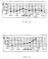
- Figure 4 is a graph showing the effect of varying the radius of curvature of the inner surface of the nose on the buckle strength of a can base.
- Figure 5 is a graph showing the effect of varying the radius of curvature of the inner surface of the nose on the buckle strength of a can base when the diameter of the nose is varied so as to maintain approximately constant depth of penetration at nesting.
- Figure 6 is a longitudinal cross-section taken through a base forming station according to the current invention.
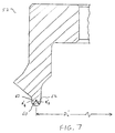
- Figure 7 is a longitudinal cross-section taken through the nose punch according to the current invention shown in Figure 6.
- A can 1 according to the current invention is shown in Figure 1. As is conventional, the can comprises an
end 3, in which an opening is formed, and a can body. The can body is formed by a cylindrical side wall 4 and abase 6 that is integrally formed with the side wall. The side wall 4 has a diameter D1. As is also conventional, the can body is made from a metal, such as steel or, more preferably, aluminium, such as type 3204, 3302 or 3004 aluminium plate having an H-19 temper. - As shown in Figure 2, the
can base 6 comprises an approximatelyfrustoconical portion 8 that extends downwardly and inwardly from the side wall 4. Thefrustoconical portion 8 includes anarcuate section 10, having a radius of curvature R1, that forms a smooth transition into the side wall 4. Thefrustoconical portion 8 also preferably includes a straight section that forms an angle α with respect to theaxis 7 of the side wall 4. - As also shown in Figure 2, an
annular nose 16 extends downwardly from thefrustoconical portion 8. Thenose 16 preferably comprises inner and outer approximatelyfrustoconical walls 12 and 13, respectively. It should be noted that theinner wall 12 is sometimes referred to in the art as the "chime".
Preferably, theinner wall 12 has a straight section that forms an angle γ with respect to theaxis 7 of the side wall 4, while the outer wall 13 has a straight section that forms an angle β with respect to the axis. The inner andouter walls 12 and 13 are joined by a circumferentially extendingarcuate section 18. Theinner wall 12 includes anarcuate section 22, having a radius of curvature R5, that forms a smooth transition into acentre portion 24 of thebase 6. The outer wall 13 includes anarcuate section 14, having a radius of curvature R2, that forms a smooth transition into thefrustoconical portion 8. - In transverse cross-section, the portion of the
inner surface 29 of thearcuate section 18 of thenose 16 adjacent theinner wall 12 has a radius of curvature R3. Similarly, the portion of theinner surface 29 of thearcuate section 18 adjacent the outer wall 13 has a radius of curvature R4. The radii of curvature of theouter surface 30 of thenose 16 will be equal to the radii of curvature of theinner surface 29 plus the thickness of the metal in thearcuate portion 18 of the nose, which is generally essentially the same as the starting sheet metal. Preferably, R3 equals R4. Most preferably, theinner surface 29 of thearcuate portion 18 is entirely formed by a sector of a circle so that only one radius of curvature forms the entirety of thearcuate portion 18 of inner surface of thenose 16, as shown in Figure 2. The centre 19 of the radius of curvature R3 forms a circle of diameter D2 as it extends around the circumference of thebase 6. Thebase 27 of thenose 16, on which thecan 1 rests when in the upright orientation, is also formed around diameter D2. Thecentre 21 of radius of curvature R1 of thearcuate section 10 is displaced from the centre 19 of radius of curvature R3 in the axial direction by a distance Y. Preferably, as the value of R3 is increased, as discussed below, the value of Y is decreased so that the sum of Y + R3 remains constant. - An approximately dome-shaped
centre portion 24 extends upwardly and inwardly from thenose 16. The mostcentral section 26 of thecentre portion 24 is disc-shaped, having a diameter D3 and being substantially flat. Anannular portion 25 of thecentre portion 24 is arcuate in transverse cross-section, having a radius of curvature R6, and connects thecentral section 26 to theinner wall 12 of thenose 16. Thecan base 6 has a dome height H that extends from thebase 27 of thenose 16 to the top of thecentre portion 24. - As shown in Figure 3, when two similarly constructed cans are stacked one on top of the other, the
base 6 of the upper can will penetrate into theend 3 of the lower can so that thebase 27 of thenose 16 of the upper can extends a distance d below the lip formed on the seaming panel 40 of the lower can. - Figure 4 shows the results of a finite element analysis, or FEA, aimed at showing how the buckle strength, defined as discussed above, varies with the radius of curvature of the
nose 16 in the base of a can having a 202 end and employing the geometry defined in Table I and shown in Figure 2. - A 202 end can having a base defined by the geometry specified in Table I and with a
nose 16 having aninner surface 29 with a radius of curvature R3 of 0.05 inch (1.27 mm) is known in the prior art. As shown in Figure 4, increasing the radius of curvature R3 of the noseinner surface 29 to 0.06 inch (1.524 mm) results in a dramatic increase in buckle strength. Specifically, the finite element analysis predicted that, contrary to the conventional wisdom in the can making art, increasing the nose inner surface radius from 0.05 inch (1.27 mm) to 0.06 inch (1.524 mm) in such a can base would increase the buckle strength by almost 10%, from 95 psi to 104 psi (655 to 717 kPa).Table I - Can Base Geometric Parameters For FEA Diameter D1 2.608 inches (66.24 mm) Diameter D2 1.904 inches (48.36 mm) Diameter D3 0.100 inch (2.54 mm) Radius R1 0.170 inch (4.32 mm) Radius R2 0.080 inch (2.03 mm) Radius R3 Variable Radius R4 Equals R3 Radius R5 0.060 inch (1.52 mm) Radius R6 1.550 inch (39.37 mm) Distance Y + R3 0.361 inch (9.17 mm) Dome Height H 0.405 inch (10.29 mm) Angle α 60° Angle β 25° Angle γ 8° - Unfortunately, increases in the nose inner surface radius of curvature beyond 0.06 inch (1.524 mm) did not yield continued increases in buckle strength, but actually reduced buckle strength, although the buckle strength remained above that obtained with the 0.05 inch (1.27 mm) radius of curvature previously employed for such a can base.
- In order to check these theoretical predictions, twelve ounce beverage cans having 202 ends were made using base geometries specified in Table I and shown in Figure 2 with three different radii of curvature R3 for the
inner surface 29 of the nose arcuate portion 18 - 0.05, 0.055 and 0.06 inch (1.27, 1.34 and 1.524 mm). Cans with each size radius of curvature were made using two different dome heights H and from two different types of 0.0108 inch (0.27 mm) thick aluminium plate - type 3204 H-19 and type 3304C5 H-19 so that, altogether, there were twelve different types of cans. The cans were tested for four strength related parameters - (i) buckle strength, defined above, (ii) base strength, obtained by measuring the minimum axial load required to collapse the can base when the side wall is supported, (iii) drop resistance, obtained by dropping water-filled cans pressurised to 60 psi (413kPa) from varying heights, and (iv) axial load, obtained by measuring the minimum axial load required to collapse the unsupported can side wall. The results of these tests, which are averaged for at least six cans of each type, are shown in Table II. In addition, the penetration depth d at stacking was measured and is shown in Table III. - The comparative strength test results shown in Table II confirm the fact that, contrary to the conventional wisdom, increasing the radius of curvature R3 of the
inner surface 29 of thearcuate portion 18 of thenose 16 on can bases of the type specified in Table I and shown in Figure 2, at least up to 0.06 inch (1.524 mm), increases, rather than decreases, the buckle resistance.Table II - Comparative Test Results - Variable Nose Radius Of Curvature Buckle Strength Base Strength Drop Resistance Axial Load inches (mm ) psi (kPa) lbs (kg) inches (mm) lbs (kg) Type 3204 H-19 Aluminium H=0.0405 (1.028) R3=0.050 (1.27) 96.7 (666) 273.7 (124.1) 6.7 (170) 232.8 (105.5) R3=0.055 (1.34) 98.3 (677) 274.7 (124.6) 6.9 (175) 229.6 (104.1) R3=0.060 (1.524) 103.8 (715) 284.7 (129.1) 7.6 (193) 205.1 (93) H=0.0415 (1.054) R3=0.050 (1.27) 97.7 (673) 273.0 (123.8) 6.7 (170) 227.6 (103.2) R3=0.055 (1.34) 99.5 (686) 276.7 (125.5) 6.8 (172) 231.2 (104.8) R3=0.060 (1.524) 105.0 (723) 283.7 (128.6) 6.8 (172) 220.9 (100.1) Type 3304C5 H-19 Aluminium H=0.0405 (1.028) R3=0.050 (1.27) 95.7 (659) 268.7 (121.8) 5.9 (149) 245.3 (111.2) R3=0.055 (1.34) 99.5 (686) 278.0 (126) 5.9 (149) 237.8 (107.8) R3=0.060 (1.524) 100.5 (692) 268.3 (121.6) 6.8 (172) 245.7 (114.4) H=0.0415 (1.054) R3=0.050 (1.27) 96.7 (666) 269.3 (122.1) 6.0 (152) 238.8 (108.3) R3=0.055 (1.34) 99.5 (686) 275.7 (125) 6.1 (154) 242.7 (110) R3=0.060 (1.524) 100.8 (694) 272.0 (123.3) 6.3 (160) 237.0 (107.5) Table III - Comparative Test Results - Nose Radius vs. Stacking Depth Radius of Curvature. R3 Stacking Depth, d 0.05 inch (1.27 mm) 0.083 inch (2.11 mm) 0.055 inch (1.34 mm) 0.069 inch (1.75 mm) 0.060 inch (1.524 mm) 0.062 inch (1.575 mm) - Unfortunately, as shown in Table III, it was found that although increasing the radius of curvature R3 of the
nose 16 at itsinner surface 29 from 0.05 inch (1.27 mm) to 0.06 inch (1.524 mm) dramatically increased buckle strength, it reduced the depth of penetration at stacking from 0.083 inch (2.108 mm) to 0.062 inch (1.575 mm). This undesirable aspect, which compromises the stackability of the can, occurred because increasing the radius R3 of the noseinner surface 29 pushes the nose outer wall 13 radially outward. - Figure 5 shows the results of a finite element analysis of a can base having the geometry specified in Table I and shown in Figure 2 except that the diameter D2 of the
nose 16 was decreased as its radius of curvature R3 at the nose inner surface increased in the manner shown in Table IV:Table IV - Variation of Nose Diameter With Nose Radius of Curvature Nose Radius, R3 (inches) Nose Diameter, D2 (inches) 0.050 (1.27 mm) 1.904 (48.36 mm) 0.060 (1.524 mm) 1.890 (48 mm) 0.065 (1.65 mm) 1.884 (47.85 mm) 0.070 (1.778 mm) 1.877 (46.68 mm) - As can be seen in Figure 5, coupling increases in the nose radius of curvature R3 with appropriate decreases in the nose diameter D2 theoretically results in constantly increasing buckle strength within the 0.05 inch (1.27 mm) to 0.07 inch (1.778 mm) nose radius range. In fact, the most dramatic increase occurs as the radius of curvature of the inside surface of the nose is increased from 0.065 inch (1.65 mm) to 0.07 inch (1.778 mm).
- In order to test the theoretical predictions from the finite element analysis discussed above, twelve ounce cans having 202 ends, and bases as shown in Figure 2, were made from Alcoa 3004 H-19 aluminium plate having an initial thickness of 0.0108 inch (0.27 mm). Half of the cans were made using a base geometry that is known in the prior art, which is designated A in Table V, and the other half were made using one embodiment of the geometry of the current invention, which is designated B. Consistent with the theoretical analysis discussed above, the two can base geometries differed in two respects. First, contrary to conventional thinking, the radius of curvature R3 of the
nose 16 at itsinner surface 29 was increased to 0.06 inch (1.524 mm). Second, the diameter D2 of the nose was decreased to 1.89 inch (48 mm).Table V - Can Base Geometric Parameters For Comparative Testing - Nose Dim. Can Base A Can Base B Diameter D1 2.608 inches (66.24 mm) 2.608 inches (66.24 mm) Diameter D2 1.904 inches (48.36 mm) 1.890 inches (45.95 mm Diameter D3 0.100 inch (2.54 mm) 0.100 inches (2.54 mm) Radius R1 0.170 inch (4.32 mm) 0.170 inch (4.32 mm) Radius R2 0.080 inch (2.03 mm) 0.080 inch (2.03 mm) Radius R3 0.050 inch (1.27 mm) 0.060 inch (1.52 mm) Radius R4 0.050 inch (1.27 mm) 0.060 inch (1.52 mm) Radius R5 0.060 inch (1.52 mm) 0.060 inch (1.52 mm) Radius R6 1.550 inch (39.37 mm) 1.550 inch (39.37 mm) Distance Y + R3 0.361 inch (9.17 mm) 0.361 inch (9.17 mm) Height H 0.405 inch (10.29 mm) 0.405 inch (10.29 mm) Angle α 60° 60° Angle β 24° 25° Angle γ 8° 8° - Comparative testing was again performed on the two groups of cans and the results, which are reported as the average for at least six cans, are shown in Table VI.
Table VI - Comparative Test Results - Varying Nose Radius And Nose Diameter Can Base A Can Base B Buckle Strength 93.7 psi (646 kPa) 100.1 psi (690 kPa) Base Strength 267.2 lbs (121.1kg) 269.7 lbs (122.3kg) Drop Resistance 7.3 inches (185 mm) 6.8 inches (173 mm) Axial Load 224.1 lbs (101.6kg) 236.8 lbs (107.4kg) Penetration Depth d 0.085 inch (2.16 mm) 0.086 inch (2.18 mm) - As can be seen, the buckle strength of the cans made according to the current invention was almost 7% greater than that of the prior art cans (i. e., 100.1 psi (690 kPa) versus 93.7 psi (646 kPa)). Such an increase is very significant. For example, it is expected that this increase in buckle strength will allow the 90 psi (620 kPa) buckle strength requirement commonly imposed by carbonated beverage bottlers to be satisfied even if the thickness of the initial metal plate is reduced from 0.0108 inch (0.274 mm) to 0.0104 inch (0.264 mm) - a reduction of almost 4%. Such a reduction in plate thickness will yield significant cost savings. The slight reduction in drop resistance is not thought to be statistically significant.
- The thickness of the metal in the
inner chime wall 12 was also measured for the two types of cans. These measurements showed that the chime wall thickness for the can base according to the current invention (type B) was 0.0003 inch (0.0076 mm) greater than that for the can base of the prior art (type A) - i.e. 0.0098 inch (0.249 mm) versus 0.0095 (0.241 mm). The increase in chime wall thickness is also significant because it shows that the current invention results in less stretching of the metal in the critical chime area (the more the metal is stretched, the thinner it becomes). Manufacturing trials have shown that this reduction in metal stretching reduces the incidence of can failure due to chime surface cracking. - Finally, by decreasing the nose diameter D2, the depth of penetration d was maintained, thereby ensuring that the increase in nose radius of curvature did not compromise stackability even in a can having a relatively small end (i.e., size 202). In this regard, the relatively small angle β of the nose outer wall 13 (i.e., 25°) also aids in obtaining good penetration. Thus, according to the current invention, if good stackability is a requirement, (i) the radius of curvature R3 of the
inner surface 29 of thearcuate portion 18 of thenose 16 should be maintained within the 0.06 inch (1.524 mm) to 0.070 inch (1.778 mm) range, (ii) the angle β of the outer wall 13 of the nose should be no greater than about 25°, and (iii) the diameter D2 of the nose should be no greater than 1.89 inch (48 mm) for cans having ends of size 202 or smaller. - Unfortunately, decreasing the nose diameter D2 will reduce the tipping stability of the can when upright. Tipping stability is important since a wobbly can may not fill properly during processing and may cause an annoyance to the ultimate consumer. Therefore, it may be undesirable to increase the nose radius of curvature to values beyond 0.07 inch (1.778 mm) in cans having 202 ends, since that would result in nose diameters less than 1.877 inch (47.68 mm) if the stacking penetration is maintained constant. Moreover, although the greatest increase in buckle strength was obtained with a 0.070 inch (1.778 mm) value for the nose inner surface radius R3, this value also results in the smallest nose diameter D2. Therefore, depending on the relative importance of the stackability versus the tipping stability requirements, the optimum value of the radius of curvature R3 of the
inner surface 29 of thearcuate portion 18 of thenose 16 may be less than 0.07 inch (1.778 mm), such as about 0.06 inch (1.524 mm) or about 0.065 inch (1.65 mm). - According to another aspect of the invention, the strength of the
base 6 can also be increased by careful adjustment of the radius R6 of thecentre portion 24. Specifically, it has been found that a surprising increase in the drop resistance can be achieved by reducing the radius R6. This reduction in R6 is preferably accompanied by an increase in the diameter D3 of the substantially flatcentral section 26 and an increase in the dome height H. - Table VII shows the results of drop resistance and buckle strength testing for 12 ounce 202 cans having three different base geometries. The base geometries were the same as those of Can Base B shown in Table V unless otherwise indicated. Each can base was formed from aluminium (Alcoa 3104) of three different initial thicknesses on a pilot line. Twelve cans were tested in each geometry/thickness. The results of tests on these cans are shown in Tables VII and VIII below.
Table VII- Comparative Test Results - Varying Dome Dimensions - Pilot Line Can Base B Can Base C Can Base D Radius R6 1.550 in (39.37 mm) 1.475 in (37.47 mm) 1.450 in (36.83 mm) Diameter D3 0.100 in (2.54 mm) 0.140 in (3.56 mm) 0.139 in (3.53 mm) Height H 0.405 in (10.29 mm) 0.405 in (10.29 mm) 0.410 in (10.41 mm) Remaining parameter the same as Table I 0.0108 inch (0.274 mm) Thickness Drop Resistance Average 6.07 inches (154 mm) 6.64 inches (169 mm) 8.00 inches (203 mm) Maximum 7 inches (178 mm) 8 inches (203 mm) 9 inches (229 mm) Minimum 5 inches (127 mm) 6 inches (152 mm) 7 inches (178 mm) Buckle Strength Average 99.8 psi (688 kPa) 98.2 psi (677 kPa) 98.7 psi (680 kPa) Maximum 100.4 psi (692 kPa) 99.0 psi (682 kPa) 99.5 psi (686 kPa) Minimum 99.2 psi (683 kPa) 97.6 psi (672 kPa) 97.5 psi (672 kPa) 0.0106 inch (0.269 mm) Thickness Drop Resistance Average 5.50 inches (139.7 mm) 6.07 inches (154 mm) 7.29 inches (185 mm) Maximum 6 inches (152.4 mm) 7 inches (177.8 mm) 8 inches (203 mm) Minimum 5 inches (127mm) 5 inches (127 mm) 6 inches (152.4mm) Buckle Strength Average 95.2 psi (656.4 kPa) 94.0 psi (648 kPa) 94.6 psi (652kPa) Maximum 95.7 psi (660kPa) 95.6 psi (659kPa) 95.8 psi (660.5kPa) Minimum 94.2 psi (649.5kPa) 93.2 psi (642.6kPa) 93.7 psi (646kPa) 0.0104 inch (0.264 mm) Thickness Drop Resistance Average 4.79 inches (121.7mm) 5.79 inches (147mm) 6.36 inches 161.5 mm) Maximum 5 inches (127 mm) 7 inches (177.8 mm) 7 inches (177.8 mm) Minimum 4 inches (101.6 mm) 4 inches (101.6 mm) 6 inches (152.4 mm) Buckle Strength Average 94.1 psi (648.8 kPa) 92.3 psi (636.4 kPa) 93.3 psi (643.3 kPa) Maximum 95.9 psi (661.2 kPa) 93.4 psi (644 kPa) 93.8 psi (646.74 kPa) Minimum 93.7 psi (646 kPa) 91.6 psi (631.6 kPa) 92.3 psi (636.4 kPa) Table VIII - % Change In Drop Resistance and Buckle Strength Over Base B Metal Thickness Base C Base D Drop Buckle Drop Buckle 0.0108 inch (0.274 mm) +8.6% -1.6% +31.8% -1.1% 0.0106 inch (0.269 mm) +10.4% -1.2% +32.5% -0.6% 0.0104 inch (0.264 mm) +20.9% -1.9% +32.8% -0.8% - As can be readily seen, by reducing the dome radius R6 to values no greater than 1.475 inches (37.465 mm) results in increased drop resistance. Specifically, reducing the dome radius R6 by 0.075 inches (1.905 mm) from 1.55 inches (39.37 mm) to 1.475 inches (37.465 mm), while simultaneously increasing the diameter D3 of the substantially flat
central dome section 26 by 0.040 inches (35.56 mm) from 0.1 inches (2.54 mm) to about 0.14 inches (3.556 mm) (base C), results in an increase in drop resistance of about 10 to 20% depending on the metal thickness and a reduction in buckle strength of only about 1 to 2%. Further reducing the dome radius R6 another 0.025 inches (0.635 mm) to about 1.45 inches (36.83 mm), while maintaining D3 at about 0.14 inches (3.56 mm) and simultaneously increasing the dome height H by 0.005 inches (0.127 mm) to about 0.41 inches (10.41 mm) (base D) increases the improvement in drop resistance to over 30% for all three metal thicknesses without further decreases in buckle strength. - In order to confirm these results, 12 ounce 202 cans were made having base geometries B and D, as above, as well as geometries E and F, defined generally in Table IX below, at two different commercial can manufacturing plants from 3004 aluminium having an initial thickness of 0.0106 inches (0.269 mm).
Table IX - Base Geometries - Varying Dome Dimensions - Manufacturing Plants Can Base E Can Base F Radius R6 1.55 in (39.37 mm) 1.50 in (38.1 mm) Diameter D3 0.100 in (2.54 mm) 0.110 in (2.79 mm) Height H 0.41 in (10.41 mm) 0.41 in (10.41 mm) Remaining parameters the same as Table I - Twelve can were made in each of the four geometries. The results of testing on these cans is shown in Table X below.
Table X- Comparative Tests Results - Varying Dome Dimensions Plant # 1 Base B Base E Base F Base D Avg. Height H 0.406 in (10.3 mm) 0.411 in (10.43 mm) 0.410 in (10.41mm) 0.411 in (10.43mm) Drop Resistance inches (mm) Average 5.5 inches (139.7) 5.3 inches (134.6) 6.0 inches (152.4) 6.9 inches (175.2) Maximum 6 inches (152.4) 6 inches (152.4) 7 inches (177.8) 8 inches (203.2) Minimum 5 inches (127) 5 inches (127) 5 inches (127) 6 inches (152.4) Buckle Strength psi (kPa) Average 96.9 psi (668) 97.5 psi (672) 96.2 psi (663) 96.4 psi (664) Maximum 97.6 psi (672) 98.2 psi (677) 96.0 psi (661) 97.0 psi (668) Minimum 96.0 psi (661) 96.2 psi (663) 94.5 psi (651) 96.0 psi (661) Axial Load lbs (kg) Average 215.7 lbs (97.8) 235.4 lbs (106.7) 239.8 lbs (108.7) 209.1 lbs (94.8) Maximum 249 lbs (112.9) 250 lbs (113.3) 257 lbs (116.5) 246 lbs (111.5) Minimum 192 lbs (87) 192 lbs (87) 220 lbs (99.7) 184 lbs (83.4) Plant #2 Base B Base E Base F Base D Drop Resistance inches (mm) Avg. Height H 0.405 in (10.28mm) 0.411 in (10.43mm) 0.411 in (10.43 mm) 0.411 in (10.43 mm) Average 6.3 inches (160) 5.75 inches (146) 6.4 inches (162.5) 6.6 inches (167.6) Maximum 7 inches (177.8) 6 inches (152.4) 7 inches (177.8) 8 inches (203.2) Minimum 5 inches (127) 5 inches (127) 6 inches (152.4) 6 inches (152.4) Buckle Strength psi (kPa) Average 96.7 psi (666) 96.7 psi (666) 96.7 psi (666) 96.2 psi (663) Maximum 97.6 psi (672) 97.6 psi (672) 97.8 psi (674) 96.9 psi (668) Minimum 96.0 psi (661) 95.8 psi (660) 95.9 psi (661) 94.9 psi (654) Axial Load lbs (Kg) Average 224.5 lbs (101.8) 235.4 lbs (106.7) 232.5 lbs (105.4) 223.6 lbs (101.4) Maximum 238 lbs (107.9) 245 lbs (111.1) 246 lbs (111.5) 232 lbs (105.2) Minimum 218 lbs (98.8) 227 lbs (102.9) 180 lbs (81.6) 209 lbs (94.8) - Since
plant # 1 had been running 0.0108 inch (0.274 mm) thick metal just prior to the test, it was suspected that the reduction in axial load for base geometry D may have been due to insufficient time to stabilise the process. Consequently, a second batch of geometry D cans were run and found to have about the same drop resistance (6.8 inches (172.7 mm) average) and buckle strength (95 psi (655 kPa) average) but significantly higher axial load (244 lbs (110.6 kg) average). - As can be seen by comparing the test results for base geometry D with those for base geometry B, reducing the dome radius R6 to 1.45 inches (36.83 mm), along with simultaneously increasing the substantially flat central section diameter D3 to 0.14 inches (3.556 mm) and increasing the dome height H to 0.410 inches (10.414 mm), resulted in a 25.5% increase in drop resistance at
plant # 1, although only a 4.8% increase at plant #2, with minimal effect on buckle strength (less than 1%). Also, comparing the results for base geometry E to base geometry B shows that increasing the dome height H without reducing the dome radius R6 actually decreases drop resistance.
Therefore, according to the current invention, in order to optimise the strength of the base of a can, such as a can having a side wall diameter of about 2.6 inches (66 mm), the radius R6 of the dome should be no greater than about 1.475 inches (37.47 mm) and, more preferably, should be about 1.45 inches (36.8 mm). In addition, the diameter D3 of the substantially flat central section should be at least about 0.14 inches (3.6 mm), and preferably should equal about 0.14 inches (3.556 mm), and the dome height H should be at least about 0.41 inches (10.4 mm), and preferably should be equal to about 0.41 inches (10.414 mm). - A preferred apparatus and method for forming the
can base 6 disclosed above is discussed below. - In conventional can forming processes, metal stock is placed into a press in which it is deformed into the shape of a cup. The cup is then conveyed to a wall ironing machine and redrawn into the general shape of the side wall and base of the finished can. Next, the redrawn cup is passed through ironing stations that eventually form the side wall into the final shape of the finished can. In addition, a base forming station is employed to shape the base of the can. A can base forming station is disclosed in aforementioned U.S. Patent No. 4,685,582 (Pulciani et al.) and U.S. Paent No 4.065.951 (LYV)
- As shown in Figure 6, an
apparatus 41 for making thecan base 6 of the current invention comprises (i) aram 42, (ii) anose punch 52, discussed further below, (iii) a substantiallycylindrical punch sleeve 44 encircling the nose punch, (iv) a centrally disposed doming die 50 having an upwardly convex forming surface, (v) asupport surface 48, (vi) anextractor 46, and (vii) acentral retaining bolt 54. - In operation, the unformed base metal stock is placed over the
punch sleeve 44 andnose punch 52. The travel of theram 42 then moves thepunch sleeve 44 and nose punch 52 toward the doming die 50 so that the metal stock is eventually pressed against the doming die forming surface and drawn over the distal surfaces of the punch sleeve and the nose punch, as shown in Figure 6, thereby forming thecan base 6. - As shown in Figure 6, the doming die 50 has a radius of curvature R6' that approximates the radius R6 of curvature of the
dome section 24. The radius of curvature R6' is displaced from the axial centreline by a distance X that approximates one half the diameter D3 of the substantially flatcentral section 26. Thus, in a preferred embodiment of the invention, the radius of curvature R6' of the doming die 50 should be no greater than about 1.475 inches (37.47 mm), and more preferably about 1.45 inches (36.8 mm). In addition, the centre of R6' should be displaced from the axial centreline by at least about 0.07 inches (1.8 mm) and the dome height H should be at least about 0.41 inches (10.4 mm). - As shown in Figure 7, according to the current invention, the
distal end 60 of thenose punch 52 has (i) a radius of curvature R3' adjacent itsinner wall 62, (ii) a radius of curvature R4' adjacent itsouter wall 63, and (iii) a diameter D2'. According to the current invention, (i) the radii of curvature R3' and R4' of thenose punch 52 are equal to the radii of curvature R3 and R4 of theinner surface 29 of thenose 16 of thecan base 16 discussed above, and (ii) the diameter D2' of the nose punch is equal to the diameter D2 of the nose of the can base discussed above. Thus, preferably, the radius of curvature R3' of thedistal end 60 of thenose punch 52 adjacent itsinner wall 62 is greater than 0.06 inch (1.524 mm). Most preferably, (i) the distal end 61 of thenose punch 52 is formed by a sector of a circle so that the radius of curvature R4' adjacent the outer wall 64 is equal to R3', (ii) the radius of curvature R3' is also less than 0.070 inch (1.778 mm), and (iii) the diameter D2' is no greater than 1.89 inch (48 mm) when making a can having a size 202 end or smaller.
Claims (15)
- A can (1) comprising a side wall (4) and an integral base (6), in which the base (6) comprises:(i) a substantially frustoconical portion (8) extending downwardly and inwardly from the side wall (4);(ii) an annular nose portion (16) extending downwardly from the substantially frustoconical portion (8), said nose portion formed by inner and outer circumferentially extending walls (12,13) joined by a downwardly convex arcuate portion (18), said arcuate portion (18) having inner and outer surfaces; and(iii) a central portion (24) extending upwardly and inwardly from said nose inner wall, said central portion being substantially dome-shaped and externally concave;characterised in that:
said radius of curvature R3 of the inner surface of the arcuate portion adjacent said nose inner wall is at least 0.06 inch (1.524 mm) and not greater than 0.07 inch (1.778 mm); and, when the can (1) is closed by an end having a diameter of approximately 2-2/16 inch (54 mm), the diameter of the nose D2 is no greater than about 1.89 inch (48 mm). - The can according to claim 1, wherein said radius of curvature R3 of the inner surface (12) is about 0.065 inch (1.651 mm).
- The can according to claim 1 or claim 2, wherein the arcuate portion has a radius of curvature R4 adjacent the outer wall (13) of at least 0.06 inch (1.524 mm).
- The can according to any one of claims 1 to 3, in which the radius of curvature R4 of the arcuate portion adjacent the outer wall is equal to the radius of curvature R3 of the arcuate portion adjacent the inner wall.
- The can according to any one of claims 1 to 4, wherein the arcuate portion (18) is a sector of a circle in transverse cross-section.
- The can according to any one of claims 1 to 5, wherein the outer wall (13) of the nose is oriented at an angle β of no greater than about 25°.
- The can according to any one of claims 1 to 6, wherein the nose (16) is made of aluminium having a thickness of less than 0.011 inch (0.28 mm).
- The can according to any one of claims 1 to 7, in which the inner and outer circumferentially extending walls comprise second and third approximately frustoconical walls (12,13), said second frustoconical wall (12) oriented at an angle of about 8° with respect to said axis, said third frustoconical wall (13) oriented at an angle of about 25° with respect to said axis, said second and third frustoconical walls joined by said downwardly convex arcuate portion (18).
- The can according to claim 8, in which said second frustoconical wall (12) is disposed radially inward from said third frustoconical wall (13).
- The can according to claim 9, wherein said domed-shaped portion (24) has a radius of curvature R6 of about 1.55 inches (39.37 mm).
- The can according to claim 9 or claim 10, wherein said radius of curvature R3 of said inner surface of said nose arcuate portion (18) is a first radius of curvature and has a first centre, and wherein said first frustoconical wall (8) comprises an arcuate portion (10) having a second radius of curvature R1 that has a second centre, said second centre displaced from said first centre by a distance Y along said axis, the sum of said distance and said first radius of curvature R3 being about 0.361 inch (9.17 mm).
- The can according to any one of claims 9 to 11, wherein said first frustoconical wall (8) is oriented at an angle of about 60° to the side wall.
- An apparatus (14) for forming the base of a can (1), said can base (6) having an annular nose (16) formed therein, comprising:a) a centrally disposed die (50) having a forming surface that is approximately dome-shaped and upwardly convex;b) a nose punch (52) movable relative to said die, said nose punch having a distal end (61), said distal end formed by inner and outer circumferentially extending walls (62,63) joined by an externally convex arcuate portion (60); andc) a ram (42) for causing relative motion between said nose punch and said die;characterised in that said arcuate portion (60) has a radius of curvature R3' adjacent said inner wall (62)of at least 0.060 inch (1.524 mm) and not more than 1.89 inches (48 mm), and, when adapted to make a can having a size of 2-2/16 inch (54 mm) or smaller, the diameter D2' is no greater than 1.89 inches (48 mm)
- An apparatus according to claim 13, in which said forming surface has a radius of curvature R6' no greater than about 1.475 inches (37.465 mm); and the arcuate portion is downwardly convex.
- The apparatus according to claim 14, wherein said forming surface has a radius of curvature R6 no greater than about 1.45 inches (36.83 mm).
Priority Applications (2)
| Application Number | Priority Date | Filing Date | Title |
|---|---|---|---|
| DK01200092T DK1127795T3 (en) | 1998-06-03 | 1999-06-02 | Can bottom with improved pressure resistance and apparatus for making them |
| EP01200092A EP1127795B1 (en) | 1998-06-03 | 1999-06-02 | Can bottom having improved pressure resistance and apparatus for making same |
Applications Claiming Priority (3)
| Application Number | Priority Date | Filing Date | Title |
|---|---|---|---|
| US9000098A | 1998-06-03 | 1998-06-03 | |
| US90000 | 1998-06-03 | ||
| PCT/US1999/012269 WO1999062765A1 (en) | 1998-06-03 | 1999-06-02 | Can bottom having improved strength and apparatus for making same |
Related Child Applications (1)
| Application Number | Title | Priority Date | Filing Date |
|---|---|---|---|
| EP01200092A Division EP1127795B1 (en) | 1998-06-03 | 1999-06-02 | Can bottom having improved pressure resistance and apparatus for making same |
Publications (2)
| Publication Number | Publication Date |
|---|---|
| EP1093432A1 EP1093432A1 (en) | 2001-04-25 |
| EP1093432B1 true EP1093432B1 (en) | 2006-01-04 |
Family
ID=22220611
Family Applications (2)
| Application Number | Title | Priority Date | Filing Date |
|---|---|---|---|
| EP01200092A Expired - Lifetime EP1127795B1 (en) | 1998-06-03 | 1999-06-02 | Can bottom having improved pressure resistance and apparatus for making same |
| EP99955250A Expired - Lifetime EP1093432B1 (en) | 1998-06-03 | 1999-06-02 | Can bottom having improved strength and apparatus for making same |
Family Applications Before (1)
| Application Number | Title | Priority Date | Filing Date |
|---|---|---|---|
| EP01200092A Expired - Lifetime EP1127795B1 (en) | 1998-06-03 | 1999-06-02 | Can bottom having improved pressure resistance and apparatus for making same |
Country Status (15)
| Country | Link |
|---|---|
| US (3) | US6131761A (en) |
| EP (2) | EP1127795B1 (en) |
| CN (1) | CN1200847C (en) |
| AR (1) | AR018444A1 (en) |
| AT (2) | ATE314964T1 (en) |
| AU (1) | AU4329199A (en) |
| BR (1) | BR9910845A (en) |
| CA (1) | CA2333575C (en) |
| DE (2) | DE69929355T2 (en) |
| DK (2) | DK1127795T3 (en) |
| ES (2) | ES2223726T3 (en) |
| MX (1) | MXPA00011819A (en) |
| MY (1) | MY124069A (en) |
| PT (1) | PT1127795E (en) |
| WO (1) | WO1999062765A1 (en) |
Families Citing this family (69)
| Publication number | Priority date | Publication date | Assignee | Title |
|---|---|---|---|---|
| US6296139B1 (en) * | 1999-11-22 | 2001-10-02 | Mitsubishi Materials Corporation | Can manufacturing apparatus, can manufacturing method, and can |
| US7380684B2 (en) | 1999-12-08 | 2008-06-03 | Metal Container Corporation | Can lid closure |
| US6640149B1 (en) * | 2000-03-21 | 2003-10-28 | Alcan International Limited | System and method of developing a can bottom profile and a can with a domed bottom structure |
| WO2002057137A2 (en) * | 2001-01-19 | 2002-07-25 | Ball Corporation | Beverage can end with reduced countersink |
| US6419110B1 (en) | 2001-07-03 | 2002-07-16 | Container Development, Ltd. | Double-seamed can end and method for forming |
| US6748789B2 (en) * | 2001-10-19 | 2004-06-15 | Rexam Beverage Can Company | Reformed can end for a container and method for producing same |
| GB2383968B (en) * | 2002-01-15 | 2005-07-27 | Rolls Royce Plc | Friction welding |
| US7263868B2 (en) * | 2003-04-03 | 2007-09-04 | Ball Corporation | Method and apparatus for reforming and reprofiling a bottom portion of a container |
| US6837089B2 (en) * | 2003-04-03 | 2005-01-04 | Ball Corporation | Method and apparatus for reforming and reprofiling a bottom portion of a container |
| US7398894B2 (en) * | 2003-11-24 | 2008-07-15 | Metal Container Corporation | Container bottom, method of manufacture, and method of testing |
| US7201031B2 (en) * | 2004-02-06 | 2007-04-10 | Belvac Production Machinery, Inc. | Flanging process improvement for reducing variation in can body flange width |
| US7472800B2 (en) * | 2004-03-05 | 2009-01-06 | Rexam Beverage Can Company | Bottom profile for drawn and ironed can body |
| US20060071005A1 (en) | 2004-09-27 | 2006-04-06 | Bulso Joseph D | Container end closure with improved chuck wall and countersink |
| ITMI20042517A1 (en) * | 2004-12-27 | 2005-03-27 | Frattini Costr Mecc | DEVICE FOR SELECTIVE AND PROGRESSIVE LOCKING OF METALLIC CONTAINERS |
| US7506779B2 (en) | 2005-07-01 | 2009-03-24 | Ball Corporation | Method and apparatus for forming a reinforcing bead in a container end closure |
| US10370142B2 (en) * | 2006-06-27 | 2019-08-06 | Stephen P. Palisin, Jr. | Shipping container |
| EP1813540A1 (en) * | 2006-01-30 | 2007-08-01 | Impress Group B.V. | Can end for a can and such can |
| EP1927554A1 (en) * | 2006-11-29 | 2008-06-04 | Impress Group B.V. | Pressurized can, such as an aerosol can |
| US7980413B2 (en) * | 2007-07-25 | 2011-07-19 | Crown Packaging Technology, Inc. | Base for metallic container |
| USD653124S1 (en) | 2007-12-17 | 2012-01-31 | Silgan Containers Llc | Container |
| USD672663S1 (en) | 2008-02-27 | 2012-12-18 | Silgan Containers Llc | Container |
| US8141741B2 (en) | 2008-02-27 | 2012-03-27 | Silgan Containers Llc | Vacuum container with protective features |
| USD652740S1 (en) | 2008-02-27 | 2012-01-24 | Silgan Containers Llc | Container |
| USD614970S1 (en) | 2008-03-28 | 2010-05-04 | Silgan Containers Llc | Container |
| USD632189S1 (en) | 2008-03-28 | 2011-02-08 | Silgan Containers Llc | Container |
| USD632188S1 (en) | 2008-03-28 | 2011-02-08 | Silgan Containers Llc | Container |
| USD641261S1 (en) | 2008-03-28 | 2011-07-12 | Silgan Containers, Llc | Container |
| USD632190S1 (en) | 2008-03-28 | 2011-02-08 | Silgan Containers Llc | Container |
| USD626015S1 (en) | 2008-03-28 | 2010-10-26 | Silgan Containers Llc | Container |
| USD632187S1 (en) | 2008-03-28 | 2011-02-08 | Silgan Containers Llc | Container |
| USD653562S1 (en) | 2008-04-04 | 2012-02-07 | Silgan Containers Llc | Container |
| USD653563S1 (en) | 2008-04-04 | 2012-02-07 | Silgan Containers Llc | Container |
| USD653123S1 (en) | 2008-04-04 | 2012-01-31 | Silgan Containers Llc | Container |
| USD652741S1 (en) | 2008-04-04 | 2012-01-24 | Silgan Containers Llc | Container |
| USD588021S1 (en) | 2008-04-04 | 2009-03-10 | Silgan Containers Corporation | Container |
| USD612732S1 (en) | 2008-05-12 | 2010-03-30 | Silgan Containers Llc | Container |
| USD614969S1 (en) | 2008-05-12 | 2010-05-04 | Silgan Containers Llc | Container |
| USD624438S1 (en) | 2008-05-12 | 2010-09-28 | Silgan Containers, Llc | Container |
| USD652742S1 (en) | 2008-05-12 | 2012-01-24 | Silgan Containers Llc | Container |
| USD620377S1 (en) | 2008-05-12 | 2010-07-27 | Silgan Containers Llc | Container |
| USD607727S1 (en) | 2008-05-12 | 2010-01-12 | Silgan Containers Llc | Container |
| USD638311S1 (en) | 2008-05-12 | 2011-05-24 | Silgan Containers, Llc | Container |
| USD649887S1 (en) | 2008-05-12 | 2011-12-06 | Silgan Containers Llc | Container |
| USD615877S1 (en) | 2009-02-05 | 2010-05-18 | Silgan Containers Llc | Container |
| USD651527S1 (en) | 2009-02-05 | 2012-01-03 | Silgan Containers Llc | Container |
| USD631759S1 (en) | 2009-03-02 | 2011-02-01 | Silgan Containers Llc | Container |
| USD614049S1 (en) | 2009-03-02 | 2010-04-20 | Silgan Containers Llc | Container |
| USD653125S1 (en) | 2009-09-09 | 2012-01-31 | Silgan Containers Llc | Container |
| USD653126S1 (en) | 2009-09-30 | 2012-01-31 | Silgan Containers Llc | Container |
| CN105234237B (en) * | 2009-10-21 | 2018-07-20 | 斯多里机械有限责任公司 | Container and the cup and their manufacture tool and correlation technique being formed selectively |
| USD651526S1 (en) | 2009-12-29 | 2012-01-03 | Silgan Containers Llc | Container |
| USD658078S1 (en) | 2010-04-30 | 2012-04-24 | Silgan Containers Llc | Container |
| USD656042S1 (en) | 2010-10-01 | 2012-03-20 | Silgan Containers Llc | Container |
| US8727169B2 (en) | 2010-11-18 | 2014-05-20 | Ball Corporation | Metallic beverage can end closure with offset countersink |
| CN103357734B (en) * | 2013-07-16 | 2015-04-22 | 上海梅山钢铁股份有限公司 | Taper blank-holding and deep-drawing stamping method |
| MX2016007739A (en) * | 2013-12-16 | 2017-02-13 | Ball Europe Gmbh | Can body. |
| US9621707B2 (en) | 2014-01-07 | 2017-04-11 | 20/20 Cte, Llc | System and method for discouraging inappropriate use of a mobile device |
| US11356549B2 (en) | 2014-01-07 | 2022-06-07 | Brian Way | System and method for discouraging inappropriate use of a mobile device |
| EP3218127B1 (en) | 2014-11-12 | 2022-02-09 | Ekl Machine Company | Flange projection control system and method |
| DE102015204654A1 (en) * | 2015-03-13 | 2016-09-15 | Ball Europe Gmbh | can body |
| DE102015215590A1 (en) * | 2015-08-14 | 2017-02-16 | Ball Europe Gmbh | Cans for beverage cans |
| US20180170606A1 (en) * | 2016-12-19 | 2018-06-21 | Stolle Machinery Company, Llc | Truncated dome cup |
| USD827685S1 (en) | 2016-12-19 | 2018-09-04 | Stolle Machinery Company, Llc | Truncated dome cup |
| USD839935S1 (en) | 2016-12-19 | 2019-02-05 | Stolle Machinery Company, Llc | Truncated dome cup |
| WO2018195525A1 (en) | 2017-04-21 | 2018-10-25 | Can Forming Technologies, Llc | Dome formation profile & method of lightweight container design and manufacture |
| CN113169412A (en) * | 2018-12-20 | 2021-07-23 | 希尔康容器有限责任公司 | End reinforced battery cell spacer |
| CN114616185A (en) * | 2019-12-03 | 2022-06-10 | 东洋制罐株式会社 | Tank container |
| CN115135581B (en) * | 2020-03-18 | 2024-03-19 | 东洋制罐株式会社 | Tank container and method for manufacturing the same |
| US11435730B2 (en) * | 2020-06-04 | 2022-09-06 | The Boeing Company | System and method for forming an integrally-stiffened, curved metallic panel |
Family Cites Families (38)
| Publication number | Priority date | Publication date | Assignee | Title |
|---|---|---|---|---|
| US3355060A (en) * | 1965-05-21 | 1967-11-28 | Reynolds Metals Co | Container with improved lift-off end closure |
| US3423985A (en) * | 1966-02-04 | 1969-01-28 | Stolle Corp | Stripper and pre-draw ring for wall-ironing can bodies |
| US3409167A (en) * | 1967-03-24 | 1968-11-05 | American Can Co | Container with flexible bottom |
| US3690507A (en) * | 1970-04-28 | 1972-09-12 | Continental Can Co | Profiled bottom wall for extruded and wall ironed cans |
| US3693828A (en) * | 1970-07-22 | 1972-09-26 | Crown Cork & Seal Co | Seamless steel containers |
| US3730383A (en) | 1971-07-29 | 1973-05-01 | Aluminum Co Of America | Container body and a method of forming the same |
| US3760751A (en) * | 1971-10-29 | 1973-09-25 | Pittsburh Aluminum | Container body and a method of forming the same |
| US3904069A (en) * | 1972-01-31 | 1975-09-09 | American Can Co | Container |
| US3905507A (en) * | 1974-04-05 | 1975-09-16 | Nat Can Corp | Profiled bottom wall for containers |
| US3942673A (en) * | 1974-05-10 | 1976-03-09 | National Can Corporation | Wall construction for containers |
| US4151927A (en) | 1974-07-12 | 1979-05-01 | Reynolds Metals Company | Container construction |
| US3979009A (en) * | 1975-03-21 | 1976-09-07 | Kaiser Aluminum & Chemical Corporation | Container bottom structure |
| US4037752A (en) * | 1975-11-13 | 1977-07-26 | Coors Container Company | Container with outwardly flexible bottom end wall having integral support means and method and apparatus for manufacturing thereof |
| US4177746A (en) * | 1976-07-29 | 1979-12-11 | Reynolds Metals Company | Method of forming a container |
| US4048934A (en) * | 1976-07-29 | 1977-09-20 | Reynolds Metals Company | Method of bottom embossing |
| US4222494A (en) * | 1977-03-04 | 1980-09-16 | Reynolds Metals Company | Container |
| JPS5325186A (en) * | 1976-08-20 | 1978-03-08 | Daiwa Can Co Ltd | Metallic can for drink containing carbon dioxide or the like |
| US4065951A (en) * | 1976-11-03 | 1978-01-03 | National Can Corporation | Split punch for drawing and ironing containers |
| DE2744461A1 (en) * | 1977-10-03 | 1979-04-12 | Wacker Chemie Gmbh | PROCESS FOR MANUFACTURING TRIMETHYLCHLOROSILANE |
| US4426013A (en) * | 1978-02-06 | 1984-01-17 | Jos. Schlitz Brewing Company | Can body |
| US4294373A (en) * | 1978-11-20 | 1981-10-13 | Ball Corporation | Lightweight metal container |
| US4646930A (en) * | 1980-02-11 | 1987-03-03 | American Can Co. | Bottom profile for a seamless container body |
| US4515284A (en) * | 1980-08-21 | 1985-05-07 | Reynolds Metals Company | Can body bottom configuration |
| US4381061A (en) * | 1981-05-26 | 1983-04-26 | Ball Corporation | Non-paneling container |
| US4412627A (en) * | 1981-05-29 | 1983-11-01 | Metal Container Corporation | Drawn and ironed can body |
| GB2114031B (en) | 1982-02-02 | 1985-10-09 | Metal Box Plc | Method of forming containers |
| US4472440A (en) * | 1982-02-09 | 1984-09-18 | Maryland Cup Corporation | Package containing a moisture resistant edible baked container |
| US4685582A (en) * | 1985-05-20 | 1987-08-11 | National Can Corporation | Container profile with stacking feature |
| US5209099A (en) * | 1985-03-15 | 1993-05-11 | Weirton Steel Corporation | Draw-process methods, systems and tooling for fabricating one-piece can bodies |
| US4617778A (en) * | 1985-12-19 | 1986-10-21 | The Suter Company, Inc. | Apparatus to facilitate hand packing of containers |
| US4785607A (en) * | 1987-10-16 | 1988-11-22 | The Suter Company, Inc. | Apparatus to facilitate hand packing of containers of different sizes |
| GB8814938D0 (en) | 1988-06-23 | 1988-07-27 | Metal Box Plc | Method for roll forming & apparatus for carrying out method |
| JPH0675737B2 (en) * | 1989-06-27 | 1994-09-28 | 東洋製罐株式会社 | Molding method for can bodies for two-piece cans |
| JPH05338640A (en) | 1990-09-17 | 1993-12-21 | Aluminum Co Of America <Alcoa> | Base profile of container made by drawing and manufacture thereof |
| MX9101632A (en) * | 1990-10-22 | 1992-06-05 | Ball Corp | METHOD AND APPARATUS TO REINFORCE THE BASE OR BOTTOM OF A CONTAINER |
| US5540352A (en) * | 1991-07-24 | 1996-07-30 | American National Can Company | Method and apparatus for reforming can bottom to provide improved strength |
| US5605069A (en) * | 1995-04-12 | 1997-02-25 | Ball Corporation | Beverage container with wavy transition wall geometry and method for producing the same |
| US5730314A (en) * | 1995-05-26 | 1998-03-24 | Anheuser-Busch Incorporated | Controlled growth can with two configurations |
-
1999
- 1999-06-02 DE DE69929355T patent/DE69929355T2/en not_active Expired - Lifetime
- 1999-06-02 EP EP01200092A patent/EP1127795B1/en not_active Expired - Lifetime
- 1999-06-02 AU AU43291/99A patent/AU4329199A/en not_active Abandoned
- 1999-06-02 MX MXPA00011819A patent/MXPA00011819A/en active IP Right Grant
- 1999-06-02 CN CN99809038.7A patent/CN1200847C/en not_active Expired - Fee Related
- 1999-06-02 DE DE69919375T patent/DE69919375T2/en not_active Expired - Lifetime
- 1999-06-02 DK DK01200092T patent/DK1127795T3/en active
- 1999-06-02 ES ES01200092T patent/ES2223726T3/en not_active Expired - Lifetime
- 1999-06-02 AT AT99955250T patent/ATE314964T1/en active
- 1999-06-02 ES ES99955250T patent/ES2253921T3/en not_active Expired - Lifetime
- 1999-06-02 WO PCT/US1999/012269 patent/WO1999062765A1/en active IP Right Grant
- 1999-06-02 EP EP99955250A patent/EP1093432B1/en not_active Expired - Lifetime
- 1999-06-02 CA CA002333575A patent/CA2333575C/en not_active Expired - Fee Related
- 1999-06-02 PT PT01200092T patent/PT1127795E/en unknown
- 1999-06-02 DK DK99955250T patent/DK1093432T3/en active
- 1999-06-02 BR BR9910845-3A patent/BR9910845A/en not_active IP Right Cessation
- 1999-06-02 AT AT01200092T patent/ATE273180T1/en active
- 1999-06-03 US US09/325,591 patent/US6131761A/en not_active Expired - Lifetime
- 1999-06-03 AR ARP990102633A patent/AR018444A1/en active IP Right Grant
- 1999-06-03 MY MYPI99002228A patent/MY124069A/en unknown
-
2000
- 2000-04-25 US US09/557,522 patent/US6220073B1/en not_active Expired - Lifetime
-
2001
- 2001-02-28 US US09/795,236 patent/US20010009107A1/en not_active Abandoned
Also Published As
| Publication number | Publication date |
|---|---|
| ES2223726T3 (en) | 2005-03-01 |
| EP1127795A2 (en) | 2001-08-29 |
| PT1127795E (en) | 2004-10-29 |
| EP1127795B1 (en) | 2004-08-11 |
| US6131761A (en) | 2000-10-17 |
| DE69919375D1 (en) | 2004-09-16 |
| CN1200847C (en) | 2005-05-11 |
| WO1999062765A8 (en) | 2000-03-23 |
| AU4329199A (en) | 1999-12-20 |
| ES2253921T3 (en) | 2006-06-01 |
| BR9910845A (en) | 2001-02-20 |
| US6220073B1 (en) | 2001-04-24 |
| CA2333575C (en) | 2008-10-14 |
| DE69929355T2 (en) | 2006-07-13 |
| WO1999062765A1 (en) | 1999-12-09 |
| EP1093432A1 (en) | 2001-04-25 |
| US20010009107A1 (en) | 2001-07-26 |
| DK1127795T3 (en) | 2004-12-13 |
| DE69929355D1 (en) | 2006-03-30 |
| EP1127795A3 (en) | 2001-11-28 |
| CN1310681A (en) | 2001-08-29 |
| DE69919375T2 (en) | 2005-02-24 |
| AR018444A1 (en) | 2001-11-14 |
| ATE314964T1 (en) | 2006-02-15 |
| DK1093432T3 (en) | 2006-05-22 |
| CA2333575A1 (en) | 1999-12-09 |
| MXPA00011819A (en) | 2002-04-24 |
| MY124069A (en) | 2006-06-30 |
| ATE273180T1 (en) | 2004-08-15 |
Similar Documents
| Publication | Publication Date | Title |
|---|---|---|
| EP1093432B1 (en) | Can bottom having improved strength and apparatus for making same | |
| US10843845B2 (en) | Can shell and double-seamed can end | |
| US4768672A (en) | Container profile with stacking feature | |
| US4953738A (en) | One piece can body with domed bottom | |
| EP1667803B1 (en) | Can shell for a can end | |
| US5222385A (en) | Method and apparatus for reforming can bottom to provide improved strength | |
| US5730314A (en) | Controlled growth can with two configurations | |
| EP0482586B1 (en) | Beverage container with improved bottom strength | |
| US5351852A (en) | Base profile for a drawn container | |
| US20030121924A1 (en) | Can shell and double-seamed can end | |
| JPH0261861B2 (en) | ||
| EP1725354B1 (en) | Bottom profile for drawn and ironed can body | |
| US5421480A (en) | Thin-walled can having a displaceable bottom | |
| JPH05177285A (en) | Pressure-resistant terminal closing member made of sheet metal | |
| US7740148B2 (en) | Container bottom | |
| EP0492861B1 (en) | Can bodies | |
| EP0337500B1 (en) | Container | |
| CN115135581B (en) | Tank container and method for manufacturing the same | |
| GB1600006A (en) | Containers | |
| JP2771343B2 (en) | Beverage container | |
| US20090272750A1 (en) | Container bottom | |
| EP0596016B1 (en) | Method and apparatus for reforming can bottom to provide improved strength | |
| CA1185544A (en) | Method for forming a tapered nestable can | |
| WO2019140170A1 (en) | Shallow can closure |
Legal Events
| Date | Code | Title | Description |
|---|---|---|---|
| PUAI | Public reference made under article 153(3) epc to a published international application that has entered the european phase |
Free format text: ORIGINAL CODE: 0009012 |
|
| 17P | Request for examination filed |
Effective date: 20001109 |
|
| AK | Designated contracting states |
Kind code of ref document: A1 Designated state(s): AT BE CH DE DK ES FI FR GB GR IE IT LI NL PT SE |
|
| R17P | Request for examination filed (corrected) |
Effective date: 20001111 |
|
| 17Q | First examination report despatched |
Effective date: 20040604 |
|
| RAP1 | Party data changed (applicant data changed or rights of an application transferred) |
Owner name: CROWN PACKAGING TECHNOLOGY, INC |
|
| GRAP | Despatch of communication of intention to grant a patent |
Free format text: ORIGINAL CODE: EPIDOSNIGR1 |
|
| GRAS | Grant fee paid |
Free format text: ORIGINAL CODE: EPIDOSNIGR3 |
|
| GRAA | (expected) grant |
Free format text: ORIGINAL CODE: 0009210 |
|
| AK | Designated contracting states |
Kind code of ref document: B1 Designated state(s): AT BE CH DE DK ES FI FR GB GR IE IT LI NL PT SE |
|
| PG25 | Lapsed in a contracting state [announced via postgrant information from national office to epo] |
Ref country code: LI Free format text: LAPSE BECAUSE OF FAILURE TO SUBMIT A TRANSLATION OF THE DESCRIPTION OR TO PAY THE FEE WITHIN THE PRESCRIBED TIME-LIMIT Effective date: 20060104 Ref country code: FI Free format text: LAPSE BECAUSE OF FAILURE TO SUBMIT A TRANSLATION OF THE DESCRIPTION OR TO PAY THE FEE WITHIN THE PRESCRIBED TIME-LIMIT Effective date: 20060104 Ref country code: CH Free format text: LAPSE BECAUSE OF FAILURE TO SUBMIT A TRANSLATION OF THE DESCRIPTION OR TO PAY THE FEE WITHIN THE PRESCRIBED TIME-LIMIT Effective date: 20060104 |
|
| REG | Reference to a national code |
Ref country code: GB Ref legal event code: FG4D |
|
| REG | Reference to a national code |
Ref country code: CH Ref legal event code: EP |
|
| REG | Reference to a national code |
Ref country code: IE Ref legal event code: FG4D |
|
| REF | Corresponds to: |
Ref document number: 69929355 Country of ref document: DE Date of ref document: 20060330 Kind code of ref document: P |
|
| REG | Reference to a national code |
Ref country code: SE Ref legal event code: TRGR |
|
| REG | Reference to a national code |
Ref country code: DK Ref legal event code: T3 |
|
| REG | Reference to a national code |
Ref country code: GR Ref legal event code: EP Ref document number: 20060400921 Country of ref document: GR |
|
| REG | Reference to a national code |
Ref country code: ES Ref legal event code: FG2A Ref document number: 2253921 Country of ref document: ES Kind code of ref document: T3 |
|
| REG | Reference to a national code |
Ref country code: CH Ref legal event code: PL |
|
| ET | Fr: translation filed | ||
| PLBE | No opposition filed within time limit |
Free format text: ORIGINAL CODE: 0009261 |
|
| STAA | Information on the status of an ep patent application or granted ep patent |
Free format text: STATUS: NO OPPOSITION FILED WITHIN TIME LIMIT |
|
| 26N | No opposition filed |
Effective date: 20061005 |
|
| PGFP | Annual fee paid to national office [announced via postgrant information from national office to epo] |
Ref country code: DK Payment date: 20070514 Year of fee payment: 9 |
|
| PGFP | Annual fee paid to national office [announced via postgrant information from national office to epo] |
Ref country code: IE Payment date: 20070515 Year of fee payment: 9 |
|
| PGFP | Annual fee paid to national office [announced via postgrant information from national office to epo] |
Ref country code: NL Payment date: 20070522 Year of fee payment: 9 |
|
| PGFP | Annual fee paid to national office [announced via postgrant information from national office to epo] |
Ref country code: PT Payment date: 20070524 Year of fee payment: 9 |
|
| PGFP | Annual fee paid to national office [announced via postgrant information from national office to epo] |
Ref country code: BE Payment date: 20070614 Year of fee payment: 9 |
|
| REG | Reference to a national code |
Ref country code: PT Ref legal event code: MM4A Free format text: LAPSE DUE TO NON-PAYMENT OF FEES Effective date: 20081202 |
|
| BERE | Be: lapsed |
Owner name: *CROWN PACKAGING TECHNOLOGY INC. Effective date: 20080630 |
|
| PG25 | Lapsed in a contracting state [announced via postgrant information from national office to epo] |
Ref country code: PT Free format text: LAPSE BECAUSE OF NON-PAYMENT OF DUE FEES Effective date: 20081202 |
|
| REG | Reference to a national code |
Ref country code: DK Ref legal event code: EBP |
|
| NLV4 | Nl: lapsed or anulled due to non-payment of the annual fee |
Effective date: 20090101 |
|
| PG25 | Lapsed in a contracting state [announced via postgrant information from national office to epo] |
Ref country code: BE Free format text: LAPSE BECAUSE OF NON-PAYMENT OF DUE FEES Effective date: 20080630 |
|
| PG25 | Lapsed in a contracting state [announced via postgrant information from national office to epo] |
Ref country code: IE Free format text: LAPSE BECAUSE OF NON-PAYMENT OF DUE FEES Effective date: 20080602 |
|
| PG25 | Lapsed in a contracting state [announced via postgrant information from national office to epo] |
Ref country code: NL Free format text: LAPSE BECAUSE OF NON-PAYMENT OF DUE FEES Effective date: 20090101 |
|
| PG25 | Lapsed in a contracting state [announced via postgrant information from national office to epo] |
Ref country code: DK Free format text: LAPSE BECAUSE OF NON-PAYMENT OF DUE FEES Effective date: 20090106 |
|
| PG25 | Lapsed in a contracting state [announced via postgrant information from national office to epo] |
Ref country code: DK Free format text: LAPSE BECAUSE OF NON-PAYMENT OF DUE FEES Effective date: 20080630 |
|
| PGFP | Annual fee paid to national office [announced via postgrant information from national office to epo] |
Ref country code: SE Payment date: 20110613 Year of fee payment: 13 Ref country code: GR Payment date: 20110624 Year of fee payment: 13 Ref country code: ES Payment date: 20110616 Year of fee payment: 13 Ref country code: FR Payment date: 20110630 Year of fee payment: 13 |
|
| PGFP | Annual fee paid to national office [announced via postgrant information from national office to epo] |
Ref country code: GB Payment date: 20110620 Year of fee payment: 13 Ref country code: AT Payment date: 20110613 Year of fee payment: 13 |
|
| PGFP | Annual fee paid to national office [announced via postgrant information from national office to epo] |
Ref country code: DE Payment date: 20110622 Year of fee payment: 13 |
|
| PGFP | Annual fee paid to national office [announced via postgrant information from national office to epo] |
Ref country code: IT Payment date: 20110628 Year of fee payment: 13 |
|
| REG | Reference to a national code |
Ref country code: DE Ref legal event code: R082 Ref document number: 69929355 Country of ref document: DE Representative=s name: RAINER CALLIES, DE Ref country code: DE Ref legal event code: R082 Ref document number: 69929355 Country of ref document: DE Representative=s name: CALLIES, RAINER, DIPL.-PHYS. DR.RER.NAT., DE |
|
| REG | Reference to a national code |
Ref country code: SE Ref legal event code: EUG |
|
| REG | Reference to a national code |
Ref country code: AT Ref legal event code: MM01 Ref document number: 314964 Country of ref document: AT Kind code of ref document: T Effective date: 20120602 |
|
| GBPC | Gb: european patent ceased through non-payment of renewal fee |
Effective date: 20120602 |
|
| PG25 | Lapsed in a contracting state [announced via postgrant information from national office to epo] |
Ref country code: IT Free format text: LAPSE BECAUSE OF NON-PAYMENT OF DUE FEES Effective date: 20120602 Ref country code: SE Free format text: LAPSE BECAUSE OF NON-PAYMENT OF DUE FEES Effective date: 20120603 |
|
| REG | Reference to a national code |
Ref country code: GR Ref legal event code: ML Ref document number: 20060400921 Country of ref document: GR Effective date: 20130104 |
|
| REG | Reference to a national code |
Ref country code: FR Ref legal event code: ST Effective date: 20130228 |
|
| REG | Reference to a national code |
Ref country code: DE Ref legal event code: R119 Ref document number: 69929355 Country of ref document: DE Effective date: 20130101 |
|
| PG25 | Lapsed in a contracting state [announced via postgrant information from national office to epo] |
Ref country code: DE Free format text: LAPSE BECAUSE OF NON-PAYMENT OF DUE FEES Effective date: 20130101 Ref country code: GB Free format text: LAPSE BECAUSE OF NON-PAYMENT OF DUE FEES Effective date: 20120602 Ref country code: FR Free format text: LAPSE BECAUSE OF NON-PAYMENT OF DUE FEES Effective date: 20120702 |
|
| PG25 | Lapsed in a contracting state [announced via postgrant information from national office to epo] |
Ref country code: GR Free format text: LAPSE BECAUSE OF NON-PAYMENT OF DUE FEES Effective date: 20130104 |
|
| PG25 | Lapsed in a contracting state [announced via postgrant information from national office to epo] |
Ref country code: AT Free format text: LAPSE BECAUSE OF NON-PAYMENT OF DUE FEES Effective date: 20120602 |
|
| REG | Reference to a national code |
Ref country code: ES Ref legal event code: FD2A Effective date: 20131018 |
|
| PG25 | Lapsed in a contracting state [announced via postgrant information from national office to epo] |
Ref country code: ES Free format text: LAPSE BECAUSE OF NON-PAYMENT OF DUE FEES Effective date: 20120603 |