DE69919375T2 - Canned bottom with increased pressure resistance and apparatus for producing the same - Google Patents
Canned bottom with increased pressure resistance and apparatus for producing the same Download PDFInfo
- Publication number
- DE69919375T2 DE69919375T2 DE69919375T DE69919375T DE69919375T2 DE 69919375 T2 DE69919375 T2 DE 69919375T2 DE 69919375 T DE69919375 T DE 69919375T DE 69919375 T DE69919375 T DE 69919375T DE 69919375 T2 DE69919375 T2 DE 69919375T2
- Authority
- DE
- Germany
- Prior art keywords
- inches
- nose
- radius
- curvature
- inch
- Prior art date
- Legal status (The legal status is an assumption and is not a legal conclusion. Google has not performed a legal analysis and makes no representation as to the accuracy of the status listed.)
- Expired - Lifetime
Links
- 229910052782 aluminium Inorganic materials 0.000 claims description 12
- XAGFODPZIPBFFR-UHFFFAOYSA-N aluminium Chemical compound [Al] XAGFODPZIPBFFR-UHFFFAOYSA-N 0.000 claims description 12
- 238000007493 shaping process Methods 0.000 claims description 8
- 229910052751 metal Inorganic materials 0.000 description 21
- 239000002184 metal Substances 0.000 description 21
- 230000009467 reduction Effects 0.000 description 11
- 238000000034 method Methods 0.000 description 9
- 230000000052 comparative effect Effects 0.000 description 8
- 230000003247 decreasing effect Effects 0.000 description 8
- 238000004519 manufacturing process Methods 0.000 description 7
- 239000002689 soil Substances 0.000 description 7
- 238000004458 analytical method Methods 0.000 description 6
- 230000035515 penetration Effects 0.000 description 6
- 230000015572 biosynthetic process Effects 0.000 description 5
- 235000013361 beverage Nutrition 0.000 description 4
- 230000000694 effects Effects 0.000 description 3
- 238000012360 testing method Methods 0.000 description 3
- 230000007704 transition Effects 0.000 description 3
- 235000013405 beer Nutrition 0.000 description 2
- 235000014171 carbonated beverage Nutrition 0.000 description 2
- 238000005429 filling process Methods 0.000 description 2
- 238000009499 grossing Methods 0.000 description 2
- 238000004806 packaging method and process Methods 0.000 description 2
- 235000014214 soft drink Nutrition 0.000 description 2
- 238000012546 transfer Methods 0.000 description 2
- XLYOFNOQVPJJNP-UHFFFAOYSA-N water Substances O XLYOFNOQVPJJNP-UHFFFAOYSA-N 0.000 description 2
- CDBYLPFSWZWCQE-UHFFFAOYSA-L Sodium Carbonate Chemical compound [Na+].[Na+].[O-]C([O-])=O CDBYLPFSWZWCQE-UHFFFAOYSA-L 0.000 description 1
- 229910000831 Steel Inorganic materials 0.000 description 1
- 238000013459 approach Methods 0.000 description 1
- 239000011324 bead Substances 0.000 description 1
- 239000011248 coating agent Substances 0.000 description 1
- 238000000576 coating method Methods 0.000 description 1
- 239000007799 cork Substances 0.000 description 1
- 238000005336 cracking Methods 0.000 description 1
- 230000001419 dependent effect Effects 0.000 description 1
- 238000013461 design Methods 0.000 description 1
- 238000011161 development Methods 0.000 description 1
- 238000005516 engineering process Methods 0.000 description 1
- 238000002474 experimental method Methods 0.000 description 1
- 238000003780 insertion Methods 0.000 description 1
- 230000037431 insertion Effects 0.000 description 1
- 238000007689 inspection Methods 0.000 description 1
- 239000000463 material Substances 0.000 description 1
- 238000005259 measurement Methods 0.000 description 1
- 238000000465 moulding Methods 0.000 description 1
- 230000002093 peripheral effect Effects 0.000 description 1
- 239000010959 steel Substances 0.000 description 1
Classifications
-
- B—PERFORMING OPERATIONS; TRANSPORTING
- B21—MECHANICAL METAL-WORKING WITHOUT ESSENTIALLY REMOVING MATERIAL; PUNCHING METAL
- B21D—WORKING OR PROCESSING OF SHEET METAL OR METAL TUBES, RODS OR PROFILES WITHOUT ESSENTIALLY REMOVING MATERIAL; PUNCHING METAL
- B21D22/00—Shaping without cutting, by stamping, spinning, or deep-drawing
- B21D22/20—Deep-drawing
- B21D22/30—Deep-drawing to finish articles formed by deep-drawing
-
- B—PERFORMING OPERATIONS; TRANSPORTING
- B65—CONVEYING; PACKING; STORING; HANDLING THIN OR FILAMENTARY MATERIAL
- B65D—CONTAINERS FOR STORAGE OR TRANSPORT OF ARTICLES OR MATERIALS, e.g. BAGS, BARRELS, BOTTLES, BOXES, CANS, CARTONS, CRATES, DRUMS, JARS, TANKS, HOPPERS, FORWARDING CONTAINERS; ACCESSORIES, CLOSURES, OR FITTINGS THEREFOR; PACKAGING ELEMENTS; PACKAGES
- B65D1/00—Rigid or semi-rigid containers having bodies formed in one piece, e.g. by casting metallic material, by moulding plastics, by blowing vitreous material, by throwing ceramic material, by moulding pulped fibrous material or by deep-drawing operations performed on sheet material
- B65D1/12—Cans, casks, barrels, or drums
- B65D1/14—Cans, casks, barrels, or drums characterised by shape
- B65D1/16—Cans, casks, barrels, or drums characterised by shape of curved cross-section, e.g. cylindrical
- B65D1/165—Cylindrical cans
Landscapes
- Engineering & Computer Science (AREA)
- Mechanical Engineering (AREA)
- Ceramic Engineering (AREA)
- Containers Having Bodies Formed In One Piece (AREA)
- Forging (AREA)
- Rigid Containers With Two Or More Constituent Elements (AREA)
- Stackable Containers (AREA)
- Shaping Metal By Deep-Drawing, Or The Like (AREA)
- Toys (AREA)
- Coiling Of Filamentary Materials In General (AREA)
Description
Die vorliegende Erfindung bezieht sich auf eine Dose, beispielsweise eine metallische, zur Verpackung kohlensäurehaltiger Getränke bestimmte Dose. Die Erfindung bezieht sich insbesondere auf eine solche Dose, welche eine erhöhte Festigkeit aufweist.The The present invention relates to a can, for example a metallic, intended for the packaging of carbonated drinks Can. The invention particularly relates to such a can, which one increased Has strength.
In der Vergangenheit sind Dosen, die zur Verpackung kohlensäurehaltiger Getränke wie z. B. Softdrinks oder Bier bestimmt sind, aus Metall, gewöhnlich aus Aluminium hergestellt worden. Solche Dosen werden üblicherweise hergestellt indem ein Dosenabschluss oder ein Deckel an einem gezogenen und geglätteten Dosengrundkörper befestigt wird, der einstückig mit einem Boden geformt worden ist.In In the past, cans are more carbonated for packaging beverages such as As soft drinks or beer, are made of metal, usually from Aluminum produced. Such doses usually become Made by a can end or a lid on a pulled and smoothed Can body is fastened, the one-piece has been shaped with a bottom.
Bestimmte, sich die Geometrie des Dosenbodens beziehende Parameter spielen eine bedeutende Rolle bei der Leistungsfähigkeit der Dose. Bei solchen Dosenböden, bei denen ein ringförmiger Nasenabschnitt benutzt wird, wird, wie im folgenden noch dargelegt werden wird, die Fähigkeit zur Stapelbildung oder zum Einsetzen des Bodens einer Dose in das oberseitige Ende einer anderen Dose durch den Durchmesser des Nasenabschnitts beeinflusst. Der Durchmesser des Nasenabschnitts beeinflusst auch die Widerstandsfähigkeit der Dose gegenüber einem Umkippen, welches beispielsweise während eines Füllvorgangs eintreten kann.Certain, play on the geometry of the bottom of the can related parameters a significant role in the efficiency of the can. In such Can bottoms, where a ring-shaped Nose section is used, as explained below will be, the ability for stacking or inserting the bottom of a can into the top end of another can through the diameter of the nose portion affected. The diameter of the nose section also influences the resilience opposite the can a tipping, which, for example, during a filling process can occur.
Zusätzlich zu der Stapelfähigkeit und der Stabilität gegenüber einem Umkippen ist die Festigkeit ein bedeutender Aspekt der Leistungsfähigkeit des Dosenbodens. Steht beispielsweise der Inhalt unter Druck, der bis zu 90 psi (620,5 kPa) betragen kann, muss die Dose hinreichend fest sein, um einer übermäßigen Verformung aufgrund des Innendrucks zu widerstehen. Ein bedeutender Festigkeitsparameter des Dosenbodens besteht somit in seiner Beulfestigkeit, welche allgemein definiert ist als Mindestwert eines Innendruckes, der erforderlich ist, um eine Umkehr bzw. eine Umformung des domartigen Abschnitts des Dosenbodens zu bewirken, nämlich der Mindestdruck, bei welchem der Mittelabschnitt des Dosenbodens ausgehend von einer zur Außenseite hin konkaven zu einer zur Außenseite hin konvexen Gestalt umklappt. Ein anderer bedeutender Parameter ist die Widerstandsfähigkeit gegenüber einem Fallen, welche definiert ist als die Mindesthöhe, die erforderlich ist, um eine Umformung des domartigen Abschnitts zu bewirken, sobald eine mit Wasser gefüllte und unter einem Druck von 60 psi (413 kPa) stehende Dose auf eine harte Oberfläche fällt.In addition to the stackability and stability across from Tipping over is an important aspect of performance of the can bottom. For example, if the content is under pressure, up to to 90 psi (620.5 kPa), the can must be sufficiently tight be to excessive deformation due to the internal pressure. An important strength parameter the bottom of the can thus consists in its Beulfestigkeit, which in general is defined as the minimum value of an internal pressure required is to reverse or reshape the dome-like section the can bottom, namely the minimum pressure at which the middle section of the can bottom starting from one to the outside concave towards one to the outside convex shape folded over. Another important parameter is the resilience across from a fall, which is defined as the minimum height required is to effect a reshaping of the dome-like section as soon as one filled with water and under a pressure of 60 psi (413 kPa) standing can on a hard surface falls.
Zu den zufriedenstellenden Leistungsanforderungen tritt ein beträchtlicher wirtschaftlicher Anreiz für Dosenhersteller hinzu, der darin besteht, die Mengen an benutztem Metall zu vermindern. Nachdem jedes Jahr Billionen von Dosen verkauft werden, sind sogar leichte Verminderungen des Metallverbrauchs wünschenswert. Die gesamte Größe und die allgemeine Gestalt der Dose wird dem Dosenhersteller durch die Getränkeindustrie vorgegeben. Dementsprechend streben Dosenhersteller stets danach, die Dicke des Metalls zu vermindern, indem Einzelheiten der Dosengeometrie verfeinert werden, um eine steifere Struktur zu bilden. Vor noch wenigen Jahren sind Aluminiumdosen aus Metall mit einer Dicke von ungefähr 0,0112 Inch (0,285 mm) hergestellt worden. Aluminiumdosen, deren Dicke auf bis zu 0,0108 Inch (0,274 mm) vermindert ist, sind jetzt verfügbar.To the satisfactory performance requirements occur considerably economic incentive for can makers which is to reduce the amounts of metal used. After every year trillions of cans are sold, even slight reductions in metal consumption are desirable. The entire size and the general shape of the can is given to the can maker by the beverage industry specified. Accordingly, can manufacturers always strive to reduce the thickness of the metal by adding details of the can geometry be refined to form a stiffer structure. Before In a few years, aluminum cans of metal with a thickness of approximately 0.0112 inches (0.285 mm). Aluminum cans whose Thickness reduced to 0.0108 inches (0.274 mm) are now available.
Eine Technik zur Erhöhung der Festigkeit des Dosenbodens, mit der beträchtliche Erfolge erzielt worden sind, besteht darin, einen zur Außenseite hin konkaven Dom in dem Dosenboden auszubilden. Getränkedosen wie z. B. diejenigen, die für Softdrinks und Bier bestimmt sind, haben üblicherweise einen Seitenwandungsdurchmesser von ungefähr 2,6 inch (66,04 mm). Üblicherweise beträgt der Krümmungsradius des Domes wenigstens 1,550 Inch (39,37 mm). Beispielsweise ist aus dem US-Patent 4,685,582 (Pulciani et al.), welches bei der Erteilung auf die National Can Corporation übertragen worden ist, eine Dose entsprechend dem Oberbegriffs des Anspruchs 1 bekannt, welche einen Seitenwandungsdurchmesser von 2,597 Inch (65,96 mm) und einen Krümmungsradius im Bereich des Domes von 2,120 Inch (53,85 mm) aufweist. In ähnlicher Weise ist in dem US-Patent 4,885,924 (Claydon et al.), welches bei der Erteilung auf die Metal Box plc übertragen worden ist, eine Dose beschrieben, die einen Seitenwandungsdurchmesser von 2,59 Inch (65,786 mm) und einen Krümmungsradius des Domes von 2,0 Inch (50,8 mm) aufweist, wohingegen in dem US-Patent 4,412,627 (Houghton et al.) welches bei der Erteilung auf die Metal Container Corp. übertragen worden ist, eine Dose offenbart ist, die einen Seitenwandungsdurchmesser von 2,6 Inch (66,04 mm) und einen Krümmungsradius des Domes von 1,75 Inch (44,45 mm) aufweist.A Technique to increase the strength of the can bottom, with which considerable success has been achieved are, is a concave to the outside dome in form the bottom of the can. beverage cans such as B. those for Soft drinks and beer are usually have a Seitenwandungsdurchmesser of about 2.6 inches (66.04 mm). Usually is the radius of curvature of the dome at least 1.550 inches (39.37 mm). For example, it is off U.S. Patent 4,685,582 (Pulciani et al.), issued to the assignee has been transferred to the National Can Corporation, a Can according to the preamble of claim 1 known which a side wall diameter of 2.597 inches (65.96 mm) and a radius of curvature in the region of the dome of 2.120 inches (53.85 mm). In a similar way U.S. Patent 4,885,924 to Claydon et al Transferred to the Metal Box plc has been described, a can having a side wall diameter of 2.59 inches (65.786 mm) and a radius of curvature of the dome of 2.0 inches (50.8 mm), whereas in U.S. Patent 4,412,627 (Houghton et al.) Which when issued on the metal container Corp. transfer has been disclosed, a can having a side wall diameter of 2.6 inches (66.04 mm) and a radius of curvature of the dome of 1.75 inches (44.45 mm).
Die Festigkeit eines mit einem Dom versehenen Dosenbodens wird weiter dadurch erhöht, dass an der Peripherie des Bodens eine sich nach unten und einwärts erstreckende kegelstumpfförmige Wandung angeformt wird, die in einer ringförmigen Sicke oder Nase endet. Die Nase weist sich in Umfangsrichtung erstreckende innere und äußere Wandungen auf, welche ebenfalls kegelstumpfförmig sein können. Die inneren und äußeren Wandungen stehen über einen zur Außenseite hin konvexen gekrümmten Abschnitt in Verbindung, der als Kreissektor geformt sein kann. Der Boden des gekrümmten Abschnitts bildet die Aufstandfläche oder die Autstandsicke, auf der die Dose in aufrechter Stellung ruht.The strength of a domed can bottom is further enhanced by forming on the periphery of the bottom a downwardly and inwardly extending frusto-conical wall terminating in an annular bead or nose. The nose has circumferentially extending inner and outer walls, which may also be frusto-conical. The inner and the outer walls are connected via a curved convex portion towards the outside, which may be formed as a circular sector. The bottom of the curved portion forms the footprint or Autstandsicke on which the can rests in an upright position.
Gemäß einer herkömmlichen Dosenherstellungstechnologie betrug der Krümmungsradius der inneren Oberfläche des gekrümmten Abschnitts der Nase bei solchen mit einem Dom versehenen, konische Wandungen aufweisenden Dosenböden ungefähr 0,05 Inch 1,27 mm) oder weniger. Vor der Entwicklung der vorliegenden Erfindung verkaufte die Muttergesellschaft der Erwerberin der vorliegenden Anmeldung, die Firma Crown Cork & Seal Company Aluminiumdosen mit Deckeln der Serie 202 (z. B. der Durchmesser des Dosendeckels gegenüber dem Boden beträgt 2-2/16 Inch (54 mm), wobei der Krümmungsradius der inneren Oberfläche der Nase 0,05 Inch (1,27 mm) betrug. In ähnlicher Weise offenbaren das US-Patent 3,730,383 (Dunn et al.), welches bei der Erteilung auf die Aluminium Company of America übertragen worden ist und das US-Patent 4,685,582 (Pulciani et al.), welches bei der Erteilung auf die National Can Corporation übertragen worden ist, eine Nase, die einen Krümmungsradius von 0,040 Inch (1,016 mm) aufweist.According to one usual Can manufacturing technology was the radius of curvature of the inner surface of the curved Section of the nose in such domed, conical Walled can floors approximately 0.05 inch by 1.27 mm) or less. Before the development of the present Invention sold the parent company of the acquirer of the present Registration, the company Crown Cork & Seal Company Aluminum cans with 202 series lids (eg diameter opposite the can lid the ground is 2-2 / 16 inches (54 mm), with the radius of curvature of the inner surface of the nose 0.05 inch (1.27 mm). In similar U.S. Patent 3,730,383 (Dunn et al.) Discloses transferred to the Aluminum Company of America and US Pat. No. 4,685,582 (Pulciani et al.) transferred to the National Can Corporation upon grant a nose having a radius of curvature of 0.040 inches (1.016 mm).
Man hat früher allgemein angenommen, dass je kleiner der Krümmungsradius der Nase bemessen ist, um so größer die Druckwiderstandsfähigkeit des Dosenbodens ausfällt, wie z. B. in dem vorstehend erwähnten US-Patent 3,730,383 dargelegt. Dementsprechend offenbaren die US-Patente 4,885,924 (oben vorgestellt), 5,069,052 (Porucznik et al.), welches bei der Erteilung auf CMB Foodcan plc übertragen worden ist und das US-Patent 5,351,852 (Trageser et al.), welches bei der Erteilung auf die Aluminium-Company of America übertragen worden ist, Verfahren zur Verminderung des Krümmungsradius der Nase, um die Festigkeit des Dosenbodens zu erhöhen. In dem US-Patent 5,351,852 wird eine Nacharbeitung der Nase vorgeschlagen, um ihren Krümmungsradius auf 0,015 Inch (0,381 mm) zu vermindern, wohingegen in dem US-Patent 5,069,052 eine Nacharbeitung der Nase vorgeschlagen wird, um ihren Krümmungsradius auf der inneren Oberfläche auf 0 zu vermindern und auf der äußeren Oberfläche auf 0,040 Inch (1,016 mm) oder weniger.you has earlier generally believed that the smaller the radius of curvature of the nose dimensioned is, the bigger the Pressure resistance the can bottom fails, such as In the aforementioned US patent 3,730,383. Accordingly, U.S. Patents 4,885,924 disclose (presented above), 5,069,052 (Porucznik et al.), which is incorporated in the Transfer to CMB Foodcan plc and US Pat. No. 5,351,852 (Trageser et al.) transferred to the Aluminum Company of America upon grant has been method of reducing the radius of curvature of the nose to the Increase the strength of the bottom of the can. In U.S. Patent 5,351,852 a reworking of the nose is proposed to its radius of curvature to 0.015 inches (0.381 mm), whereas in U.S. Patent 5,069,052 is proposed a reworking of the nose to her radius of curvature on the inner surface to diminish to 0 and on the outer surface 0.040 inches (1.016 mm) or less.
Zusätzlich zu seiner Geometrie beeinflussen die Herstellungsvorrichtung und die bei der Formgebung des Dosenbodens angewandten Techniken ihre Festigkeit. Beispielsweise können kleine Oberflächenrisse in der Domfläche des Dosenbodens entstehen, falls das Metall übermäßig gedehnt wird, und zwar bei der Formgebung der Nase. Falls – welches oft geschieht – diese Risse anfänglich sich nicht durch die gesamte metallische Wandung hindurch erstrecken, bleiben sie bei der Inspektion durch den Dosenhersteller unentdeckt. Dies kann zu einem Versagen der Dose führen, nachdem sie befüllt und geschlossen worden ist, welches vom Standpunkt des Getränkeverkäufers oder des Endverbrauchers außerordentlich unerwünscht ist. Je kleiner der Krümmungsradius der Nase, um so wahrscheinlicher wird es, dass eine solche Rissbildung auftritt. Da angenommen wird, dass der Krümmungsradius der Nase in der Nähe der inneren Wandungen einen größeren Einfluss auf die Beulfestigkeit als der Radius in der Nähe der äußeren Wandung ausübt, haben einige Dosenhersteller eine Nasengestalt verwendet, die komplizierter ausfällt als ein einfacher Kreissektor, indem zwei Krümmungsradien benutzt werden, nämlich ein erster innerer Krümmungsradius in der Nähe der äußeren Wandung von mehr als 0,060 Inch (1,524 mm) und zweiter innerer Krümmungsradius in der Nähe der inneren Wandung von weniger als 0,060 Inch (1,524 mm). Beispielsweise ist in dem US-Patent 4,431,112 (Yamaguchi), welches bei der Erteilung auf die Daiwa Can Company übertragen worden ist, ein mit einem Dom versehener Dosenboden offenbart, der keine konische Umfangswandung aufweist, der jedoch eine Nase mit einem ersten Krümmungsradius in der Nähe der inneren Wandung von ungefähr 0,035 Inch (0,9 mm) und einen zweiten Krümmungsradius in der Nähe der äußeren Wandung von ungefähr 0,091 Inch (2,3 mm) aufweist. Ein anderer Dosenhersteller hat einen mit einem Dom versehenen, konische Wandungen aufweisenden Boden bei einer Dosendeckelserie 204 verwendet, bei welchem die innere Oberfläche der Nase, deren äußere Wandung unter einem Winkel von ungefähr 26,5° bezüglich der Dosenachse geneigt verläuft, einen ersten Krümmungsradius in der Nähe der inneren Wandung der Nase von ungefähr 0,054 Inch (1,37 mm) und einen zweiten Krümmungsradius in der Nähe der äußeren Wandung von ungefähr 0,064 Inch (1,626 mm) aufweist.In addition to its geometry affect the manufacturing device and the techniques used in the molding of the can bottom their strength. For example, you can small surface cracks in the dome area of the can bottom, if the metal is overstretched, namely in the shaping of the nose. If - which often happens - this Cracks initially do not extend through the entire metallic wall, they remain undetected during inspection by the can manufacturer. This can lead to a failure of the can after it is filled and has been closed, which from the point of view of the beverage vendor or of the end user extraordinarily undesirable is. The smaller the radius of curvature the nose, the more likely it is that such cracking occurs. Since it is assumed that the radius of curvature of the nose in the Near the inner walls have a bigger impact to the buckling strength as the radius exerts near the outer wall Some can makers used a nasal shape that is more complicated fails as a simple circular sector, using two radii of curvature, namely a first inner radius of curvature near the outer wall greater than 0.060 inches (1.524 mm) and second inner radius of curvature near the inner wall is less than 0.060 inches (1.524 mm). For example is in U.S. Patent 4,431,112 (Yamaguchi), issued to the assignee transferred to the Daiwa Can Company discloses a can bottom provided with a dome which has no conical peripheral wall, but with a nose a first radius of curvature near the inner wall of about 0.035 inches (0.9 mm) and a second radius of curvature near the outer wall of about 0.091 inches (2.3 mm). Another can maker has one Domed conical walls used in a can lid series 204 in which the inner surface the nose, the outer wall at an angle of about 26.5 ° with respect to Canned axis is inclined, a first radius of curvature in nearby the inner wall of the nose of about 0.054 inches (1.37 mm) and a second radius of curvature near the outer wall of about 0.064 inches (1.626 mm).
Unabhängig von den bisher in dieser Technik erzielten Fortschritten würde es wünschenswert sein, einen Dosenboden bereitzustellen, der eine Geometrie aufweist, mittels welcher die Leistungsfähigkeit, insbesondere die Widerstandsfähigkeit gegenüber einem Ausbeulen, die Widerstandsfähigkeit gegenüber einem Fallen, die Eignung zur Stapelbildung und die r Herstellbarkeit optimiert sind.Independent of It would be desirable for the progress hitherto made in this technique be to provide a can bottom that has a geometry, by means of which the efficiency, especially the resistance across from a bulging, resistance to falling, the suitability for stacking and r manufacturability optimized are.
Eine Aufgabe der vorliegenden Erfindung besteht darin, einen Dosenboden vorzuschlagen, der eine Geometrie aufweist, durch welche die Leistungsfähigkeit, insbesondere mit Hinblick auf die Widerstandsfähigkeit gegenüber einem Ausbeulen, die Eignung zur Stapelbildung und die Herstellbarkeit optimiert sind. Diese und andere Ziele der vorliegenden Erfindung werden bei einer Dose, die aus einem Seitenwandungsabschnitt und einem einstückig mit dem Seitenwandungsabschnitt geformten Bodenabschnitt besteht entsprechend dem Anspruch 1 erreicht. Der Bodenabschnitt umfasst (i) einen ungefähr kegelstumpfförmigen Abschnitt, der sich ausgehend von dem Seitenwandungsabschnitt nach unten und einwärts erstreckt, (ii) einen ringförmigen Nasenabschnitt, der sich ausgehend von dem genannten ungefähr kegelstumpfförmigen Abschnitt nach unten erstreckt, (iii) einen im wesentlichen flachen, scheibenartig geformten Mittelabschnitt und (iv) einen ringförmigen Domabschnitt, der zwischen dem im wesentlichen flachen Mittelabschnitt und der Nase angeordnet ist, wobei der genannte ringförmige Domabschnitt in seinem Querschnitt gekrümmt und nach unten konkav ausgebildet ist, wobei der ringförmige Domabschnitt einen Krümmungsradius von nicht mehr als 1,475 Inch (37,465 mm) aufweist. Die Dosenseitenwandung hat einen Durchmesser von ungefähr 2,6 Inch (66,04 mm), wobei der Krümmungsradius des ringförmigen Domabschnitts ungefähr 1,45 Inch (36,83 mm) beträgt, wobei der im wesentlichen flache scheibenartig geformte Mittelabschnitt einen Durchmesser von wenigstens ungefähr 0,14 Inch (3,556 mm) aufweist und wobei der im wesentlichen flache scheibenartig geformte Mittelabschnitt gegenüber dem genannten Nasenabschnitt nach Maßgabe einer Höhe versetzt angeordnet ist, die wenigstens ungefähr 0,41 Inch (10,414 mm) beträgt.It is an object of the present invention to provide a can bottom having a geometry which optimizes performance, especially with regard to buckling resistance, stackability and manufacturability. These and other objects of the present invention are corresponding to a can consisting of a side wall portion and a bottom portion formed integrally with the side wall portion reaches the claim 1. The bottom portion comprises (i) an approximately frusto-conical portion extending downwardly and inwardly from the sidewall portion, (ii) an annular nose portion extending downwardly from said approximately frusto-conical portion, (iii) a substantially flat one a disc-shaped central portion and (iv) an annular dome portion disposed between the substantially flat central portion and the nose, said annular dome portion being curved in cross-section and concave downwardly, the annular dome portion having a radius of curvature of not more as 1.475 inches (37.465 mm). The can side wall has a diameter of about 2.6 inches (66.04 mm) with the radius of curvature of the annular dome portion being about 1.45 inches (36.83 mm) with the substantially flat disk-shaped central portion having a diameter of at least about 0.14 inches (3.556 mm) and wherein the substantially flat disc-like shaped central portion is offset from said nose portion in accordance with a height that is at least about 0.41 inches (10.414 mm).
Die Erfindung umfasst auch eine Vorrichtung entsprechend dem Anspruch 11 zur Herstellung eines Dosenbodens, der eine ringförmige Nase aufweist. Die Vorrichtung umfasst (i) einen mittig angeordneten, eine solche Formgebungsoberfläche aufweisenden Stempel, welche angenähert domartig gestaltet ist und zur Oberseite hin konvex ausgebildet ist, (ii) einen Nasenstempel, der relativ zu dem genannten Stempel bewegbar ist, wobei der genannte Nasenstempel ein zugekehrtes Ende aufweist, dass durch innere und äußere, sich in Umfangsrichtung erstreckende Wandungen gebildet ist, die untereinander über einen zur Unterseite hin konvex gekrümmten Abschnitt in Verbindung stehen, wobei der genannte gekrümmte Abschnitt in der Nähe der genannten inneren Wandung einen Krümmungsradius aufweist, der innerhalb eines Bereiches von 0,06 Inch bis 0,07 Inch (1,524 mm bis 1,778 mm) liegt und (iii) einen Stößel für die Bewirkung einer Relativbewegung zwischen dem Nasenstempel und dem genannten Stempel.The The invention also encompasses a device according to the claim 11 for producing a bottom of a can, which has an annular nose having. The device comprises (i) a centrally arranged, such a shaping surface having stamp, which is designed approximately dome-like and is convex toward the top, (ii) a nose stamp, which is movable relative to said punch, said Nostril has a facing end that through inner and outer, in Circumferentially extending walls is formed, with each other via a towards the bottom convex curved Section, wherein said curved section near said inner wall has a radius of curvature, the within a range of 0.06 inch to 0.07 inch (1.524 mm to 1.778 mm) and (iii) a plunger for effecting a relative movement between the nose stamp and the mentioned stamp.
Der erfindungsgemäß zentral angeordnete Stempel weist eine Formgebungsoberfläche auf, deren Krümmungsradius nicht mehr als 1,475 Inch (37,465 mm) beträgt.Of the according to the invention centrally arranged stamp has a shaping surface whose radius of curvature not more than 1.475 inches (37.465 mm).
Ein bevorzugtes Ausführungsbeispiel der Erfindung wird im Folgenden unter Bezugnahme auf die Zeichnungen beschrieben werden. Es zeigen:One preferred embodiment The invention will be described below with reference to the drawings to be discribed. Show it:
Wie
in
Wie
ebenfalls in
Im
Querschnitt gesehen weist der Abschnitt der inneren Oberfläche
Ein
angenährt
domartig gestaltetes Mittelfeld
Wie
in
Eine
mit einem Deckel des Typs 202 versehene Dose, die einen Boden aufweist,
der durch die in Tabelle I definierte Geometrie gekennzeichnet ist
und ferner eine Nase
Unglücklicherweise führen Zunahmen der Krümmungsradien der inneren Oberfläche der Nase über 0,06 Inch (1,524 mm) hinaus nicht zu weiteren Zunahmen der Beulfestigkeit sondern tatsächlich zu Verminderungen der Beulfestigkeit, obgleich der Wert der Beulfestigkeit oberhalb desjenigen Wertes blieb, der mit dem Krümmungsradius von 0,05 inch (1,27 mm) erreicht wurde, der bei früheren Dosenböden benutzt worden ist.Unfortunately to lead Increases in radii of curvature the inner surface the nose over 0.06 Inch (1.524 mm) does not lead to further increases in buckling strength but actually to diminish the buckling strength, although the value of buckling strength remained above the value with the radius of curvature of 0.05 inches (1.27 mm) used in earlier can floors has been.
Um
die theoretischen Vorhersagen zu überprüfen, wurden 12-Unzen-Getränkedosen
mit Deckeln des Typs 202 hergestellt, und zwar unter Verwendung
der in der Tabelle I dargestellten Bodengeometrie, die in
Die
die Festigkeit betreffenden Vergleichsuntersuchungen, die in Tabelle
II gezeigt sind, bestätigen
die Tatsache, dass entgegen dem herkömmlichen Kenntnistand eine
Erhöhung
des Krümmungsradius
R3 der inneren Oberfläche 

Unglücklicherweise
wurde, wie in Tabelle III gezeigt, festgestellt, dass sehr wohl
infolge einer Zunahme des Krümmungsradius
R3 der Nase
Wie
anhand der
Um
die theoretischen Vorhersagen der vorstehend dargelegten Finite-Elemente-Analyse
zu untersuchen, wurden 12-Unzen-Dosen mit Deckeln der Serie 202
und Böden
wie in
Tabelle
V – Geometrische
Parameter des Dosenbodens für
Vergleichsuntersuchungen Nasenabmessungen 

Die Vergleichsuntersuchungen wurden an den beiden Gruppen der Dosen durchgeführt und die Ergebnisse, welche als Durchschnitt von wenigstens 6 Dosen zu sehen sind, sind in Tabelle VI gezeigt.The Comparative studies were conducted on the two groups of doses carried out and the results, which as an average of at least 6 doses are shown in Table VI.
Tabelle
VI – Ergebnisse
von Vergleichsuntersuchungen – Änderungen
des Nasenradius und des Nasendurchmessers 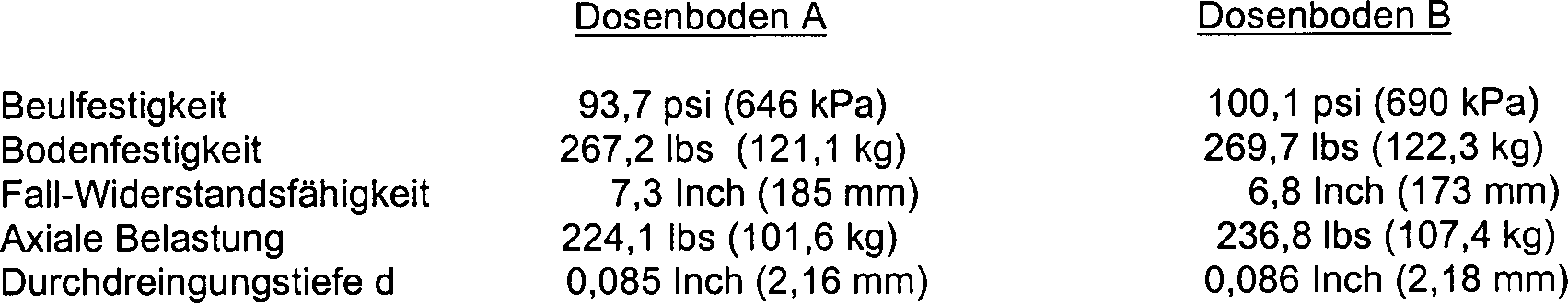
Man erkennt, dass die Beulfestigkeit der Dosen die erfindungsgemäß hergestellt wurden, nahezu um 7% größer als diejenige der Dosen ausfiel, die dem Stand der Technik zuzuordnen waren (z. B. 101,1 psi (690 kPa) gegenüber 93,7 psi (646 psi). Eine solche Zunahme ist sehr beträchtlich. Es wird beispielsweise erwartet, dass es aufgrund dieser Zunahme der Beulfestigkeit ermöglicht wird, die Anforderungen nach einer Beulfestigkeit von 90 psi (620 kPa) zu erfüllen, welche üblicherweise durch Hersteller kohlensäurehaltiger Getränke gesetzt werden, und zwar selbst dann, wenn die Dicke des anfänglichen Metallblechs von 0,0108 Inch (0,274 mm) auf 0,0104 Inch (0,264 mm) vermindert wird, somit eine Verminderung von fast 4%. Eine solche Verminderung der Blechdicke führt zu beträchtlichen Kosteneinsparungen. Die leichte Verminderung hinsichtlich der Widerstandsfähigkeit gegenüber einem Fallen wird als statistisch nicht signifikant angesehen.you recognizes that the buckling strength of the cans made in accordance with the invention were nearly 7% larger than that of the cans precipitated that attributed to the prior art were (e.g., 101.1 psi (690 kPa) versus 93.7 psi (646 psi) such increase is very considerable. For example, it is expected to be due to this increase the buckling strength allows is the requirements for a buckling strength of 90 psi (620 kPa), which usually by manufacturer carbonated Drinks set be, even if the thickness of the initial Metal sheet from 0.0108 inches (0.274 mm) to 0.0104 inches (0.264 mm) is reduced, thus a reduction of almost 4%. Such Reduction of the sheet thickness leads to considerable Cost savings. The slight reduction in the resistance across from Falling is not considered statistically significant.
Die
Dicke des Metalls im Bereich der inneren Glockenwandung
Indem
schließlich
der Durchmesser D2 der Nase vermindert wird,
wobei die Durchdringungstiefe d beibehalten wurde, wurde sichergestellt,
dass die Zunahme des Krümmungsradius
der Nase nicht die Stapelfähigkeit
beeinträchtigte,
und zwar selbst dann, wenn die Dose einen relativ kleinen Deckel
hat (z. B. Größe 202). In
dieser Hinsicht trug der relativ kleine Winkel β der äußeren Wandung
Unglücklicherweise
wird eine Verminderung des Durchmesser D2 der
Nase die Kippstabilität
der Dose vermindern, wenn diese aufrecht steht. Die Kippstabilität ist von
Bedeutung, da ein unsicherer Stand der Dose einem korrekten Füllvorgang
während
der Behandlung entgegen steht und dem Endverbraucher Ärger bereiten
kann. Es kann deshalb nicht wünschenswert
sein, den Krümmungsradius
der Nase auf Werte jenseits von 0,07 Inch (1,778 mm) bei Dosen mit
Deckeln der Größe 202 zu
erhöhen,
da dies zu Nasendurchmessern führen
würde,
die kleiner als 1,877 Inch (47,68 mm) ausfallen, falls die Durchdringung
während
der Stapelbildung konstant gehalten wird. Obgleich die größte Zunahme
der Beulfestigkeit mit einem Wert von 0,070 Inch (1,778 mm) für den Krümmungsradius
R3 der inneren Oberfläche der Nase erreicht wurde,
führt dieser
Wert auch zu dem kleinsten Nasendurchmesser D2.
In Anhängigkeit
von der relativen Bedeutung der Anforderungen betreffend die Stapelfähigkeit
gegenüber
der Kippstabilität
kann der optimale Weg des Krümmungsradius
R3 der inneren Oberfläche
Erfindungsgemäß kann die
Festigkeit des Bodens
Die Tabelle VII zeigt die Ergebnisse der Untersuchungen an 12-Unzen-Dosen des Typs 202 mit drei unterschiedlichen Bodengeometrien hinsichtlich der Widerstandsfähigkeit gegenüber Fallen und der Beulfestigkeit. Die Bodengeometrien entsprachen denjenigen der Dosenböden B, die in Tabelle V gezeigt sind, soweit dies nicht anders angegeben ist. Ein jeder Dosenboden wurde auf einer Pilotanlage ausgehend von drei unterschiedlichen Dicken aus Aluminium (Alcoa 3104) hergestellt. Zwölf Dosen wurden bei jeder Geometrie/Dicke untersucht. Die Ergebnisse der Untersuchungen an diesen Dosen ist in den nachstehenden Tabellen VII und VIII gezeigt.The Table VII shows the results of studies on 12-ounce cans of the type 202 with three different ground geometries regarding the resilience across from Falling and the buckling strength. The soil geometries corresponded to those the can floors B shown in Table V, unless otherwise specified is. Each can bottom was based on a pilot plant made of three different thicknesses of aluminum (Alcoa 3104). Twelve doses were examined at each geometry / thickness. The results of Studies on these doses are shown in the tables below VII and VIII shown.
Tabelle
VII – Ergebnisse
von Vergleichsuntersuchungen – Änderungen
der Domabmessungen – Versuchslinie 

Tabelle
VIII – Prozentuelle
Veränderung
der Fall-Widerstandsfähigkeit
und der Beulfestigkeit gegenüber
dem Boden B 
Wie
deutlich erkennbar ist, führt
eine Verminderung des Domradius R6 auf Werte
von nicht mehr als 1,475 Inch (37,465 mm) zu einer erhöhten Widerstandsfähigkeit
gegenüber
Fallen. Insbesondere führt
eine Verminderung des Domradius R6 um 0,0675
Inch (1,905 mm) von 1,55 Inch (39,37 mm) auf 1,475 Inch (37,465 mm)
bei gleichzeitiger Zunahme des Durchmessers D3 das
im wesentlichen flachen mittleren Domabschnitts
Zur Bestätigung dieser Ergebnisse wurden 12-Unzen-Dosen des Typs 202 hergestellt, und zwar mit Bodengeometrien des Typs B und D wie oben vorgestellt und gleichermaßen mit Geometrien des Typs E und F, welche allgemein in der nachstehenden Tabelle IX definiert sind, und zwar in zwei unterschiedlichen kommerziellen Dosenherstellungslagen und ausgehend von Aluminium des Typs 3004 mit einer anfänglichen Dicke von 0,0106 Inch (0,269 mm).To confirm these results, Type 202 12 ounce cans were made, with Type B and Type D bottom geometries as presented above, and similarly with E and F geometries generally defined in Table IX below, in two different commercial can production lines and starting from 3004 aluminum with an initial Di. 0.0106 inch (0.269 mm).
Tabelle
IX – Bodengeometrie – Änderungen
der Domabmessungen – Herstellungsanlagen 
Zwölf wurden nach Maßgabe der genannten vier Geometrien hergestellt. Die Untersuchungsergebnisse dieser Dosen sind in der nachstehenden Tabelle X wiedergegeben.Twelve were in accordance with made of said four geometries. The examination results these doses are given in Table X below.
Tabelle
X – Ergebnisse
von Vergleichsuntersuchungen – Änderungen
der Domabmessungen
Anlage # 1 
Anlage
# 2 

Nach dem auf der Anlage #1 ein Metall mit einer Dicke von 0,0108 Inch (0,274 mm) vor dem Versuch benutzt worden ist, wird angenommen, dass die Verminderung der axialen Belastung bei der Bodengeometrie D auf ein unzureichendes Zeitintervall zurückführbar ist, um das Verfahren zu stabilisieren. Dementsprechend wurde eine zweite Gruppe von Dosen mit der Geometrie D behandelt, wobei festgestellt wurde, dass sie die gleiche Widerstandsfähigkeit gegenüber einem Fallen aufweisen (Durchschnitt 6,8 inch (172,7 mm)) und Beulfestigkeit (Durchschnitt 244 psi), jedoch eine beträchtlich höhere axiale Belastung (Durchschnitt 244 lbs) aufwiesen.To in Appendix # 1, a 0.0108 inch thick metal (0.274 mm) before the experiment, it is assumed that that the reduction of the axial load in the ground geometry D is attributable to an insufficient time interval to the procedure to stabilize. Accordingly, a second group of doses treated with the geometry D, which was found to be the same resistance across from falling (average 6.8 inches (172.7 mm)) and buckling strength (Average 244 psi), but a considerably higher axial load (average 244 lbs).
Wie anhand eines Vergleiches der Untersuchungsergebnisse für die Bodengeometrie D mit denjenigen der Bodengeometrie B erkennbar ist, führt eine Verminderung des Domradius R6 auf 1,45 inch (36,83 mm) zusammen mit einer gleichzeitigen Zunahme des Durchmessers D3 des im wesentlichen flachen Mittelabschnitts auf 0,14 Inch (3,556 mm) und einer Zunahme der Domhöhe H auf 0,410 Inch (10,414 mm) zu einer Zunahme der Widerstandsfähigkeit gegenüber Fallen um 25,5%, und zwar bei der Anlage #1, obwohl bei der Anlage #2 lediglich eine Zunahme von 4,8% festgestellt wurde, und zwar mit minimaler Auswirkung auf die Beulfestigkeit (weniger als 1%). Ein Vergleich der Ergebnisse der Bodengeometrie E mit der Bodengeometrie B zeigt auch, dass eine Zunahme der Domhöhe H ohne Verminderung des Domradius R6 zu einer tatsächlichen Minderung der Fall-Widerstandsfähigkeit führt.As can be seen from a comparison of the test results for the bottom geometry D with those of the bottom geometry B, a reduction of the dome radius R 6 to 1.45 inches (36.83 mm) together with a simultaneous increase in the diameter D 3 of the substantially flat central portion at 0.14 inches (3.556 mm) and an increase in dome height H to 0.410 inches (10.414 mm) to a 25.5% increase in resistance to traps, Appendix # 1, although Appendix # 2 only an increase of 4.8% was observed, with minimal impact on buckling strength (less than 1%). A comparison of the results of the ground geometry E with the ground geometry B also shows that an increase in the dome height H without decreasing the dome radius R 6 results in an actual drop resistance reduction.
Gemäß der vorliegenden Erfindung sollte mit Hinblick auf eine Optimierung der Festigkeit des Bodens einer Dose wie z. B. einer Dose, welche einen Seitenwandungsdurchmesser von ungefähr 2,6 Inch (66 mm) aufweist, der Radius R6 des Domes nicht größer als ungefähr 1,475 Inch (37,47 mm) betragen und sollte vorzugsweise ungefähr 1,45 Inch (36,8 mm) betragen. Zusätzlich sollte der Durchmesser D3 des im wesentlichen flachen Mittelabschnitts wenigstens ungefähr 0,14 Inch (3,6 mm) und vorzugsweise ungefähr 0,14 Inch (3,556 mm) betragen, wobei die Domhöhe H wenigsten ungefähr 0,41 Inch (10,41 mm) und vorzugsweise ungefähr 0,41 Inch (10,414 mm) betragen sollte.According to the present invention, with a view to optimizing the strength of the bottom of a can such. A can having a sidewall diameter of about 2.6 inches (66 mm), the radius R 6 of the dome should be no greater than about 1.475 inches (37.47 mm), and should preferably be about 1.45 inches (36 inches). 8 mm). In addition, the diameter D 3 of the substantially flat central portion should be at least about 0.14 inches (3.6 mm), and preferably about 0.14 inches (3.556 mm), with the dome height H at least about 0.41 inches (10.41 inches) mm) and preferably about 0.41 inches (10.414 mm).
Eine
bevorzugte Vorrichtung sowie ein Verfahren zur Formgebung des Dosenbodens
Bei herkömmlichen Dosenformgebungsverfahren wird Metall in eine Presse eingeführt, in welcher es zu der Gestalt einer Tasse oder eines Bechers umgeformt wird. Die Tasse wird anschließend einer Wandglättungsmaschine zugeführt und nach Maßgabe der allgemeinen Gestalt der Seitenwandungen und des Bodens der fertigen Dose nachgezogen. Im Anschluss hieran gelangt die nachgezogene Dose durch Glättungsstationen, in denen die Seitenwandungen nach Maßgabe der Endgestalt der fertigen Dose verformt werden. Zusätzlich wird eine Bodenformgebungsstation zur Gestaltung des Bodens der Dose eingesetzt. Eine Dosenformgebungsstation ist in dem vorstehend bereits erwähnten US-Patent 4,685,582 (Pulciani et al.) beschrieben worden.at usual Dosing process, metal is introduced into a press, in which transforms it into the shape of a cup or a cup becomes. The cup will follow a wall smoothing machine supplied and as required the general shape of the side walls and the bottom of the finished Dose tightened. This is followed by the redrawn box through smoothing stations, in which the side walls in accordance with the final shape of the finished Can be deformed. additionally is a soil shaping station for the design of the bottom of the Can used. A can forming station is in the above already mentioned U.S. Patent 4,685,582 (Pulciani et al.).
Wie
in
Im
Betrieb wird das unverformte metallische Bodenmaterial unter die
Stempelmuffe
Wie
in
Wie
in
Claims (12)
Applications Claiming Priority (2)
| Application Number | Priority Date | Filing Date | Title |
|---|---|---|---|
| US9000098A | 1998-06-03 | 1998-06-03 | |
| US90000 | 1998-06-03 |
Publications (2)
| Publication Number | Publication Date |
|---|---|
| DE69919375D1 DE69919375D1 (en) | 2004-09-16 |
| DE69919375T2 true DE69919375T2 (en) | 2005-02-24 |
Family
ID=22220611
Family Applications (2)
| Application Number | Title | Priority Date | Filing Date |
|---|---|---|---|
| DE69919375T Expired - Lifetime DE69919375T2 (en) | 1998-06-03 | 1999-06-02 | Canned bottom with increased pressure resistance and apparatus for producing the same |
| DE69929355T Expired - Lifetime DE69929355T2 (en) | 1998-06-03 | 1999-06-02 | Increased strength can bottom and method of making same |
Family Applications After (1)
| Application Number | Title | Priority Date | Filing Date |
|---|---|---|---|
| DE69929355T Expired - Lifetime DE69929355T2 (en) | 1998-06-03 | 1999-06-02 | Increased strength can bottom and method of making same |
Country Status (15)
| Country | Link |
|---|---|
| US (3) | US6131761A (en) |
| EP (2) | EP1127795B1 (en) |
| CN (1) | CN1200847C (en) |
| AR (1) | AR018444A1 (en) |
| AT (2) | ATE273180T1 (en) |
| AU (1) | AU4329199A (en) |
| BR (1) | BR9910845A (en) |
| CA (1) | CA2333575C (en) |
| DE (2) | DE69919375T2 (en) |
| DK (2) | DK1127795T3 (en) |
| ES (2) | ES2223726T3 (en) |
| MX (1) | MXPA00011819A (en) |
| MY (1) | MY124069A (en) |
| PT (1) | PT1127795E (en) |
| WO (1) | WO1999062765A1 (en) |
Families Citing this family (70)
| Publication number | Priority date | Publication date | Assignee | Title |
|---|---|---|---|---|
| US6296139B1 (en) * | 1999-11-22 | 2001-10-02 | Mitsubishi Materials Corporation | Can manufacturing apparatus, can manufacturing method, and can |
| US7380684B2 (en) | 1999-12-08 | 2008-06-03 | Metal Container Corporation | Can lid closure |
| US6640149B1 (en) * | 2000-03-21 | 2003-10-28 | Alcan International Limited | System and method of developing a can bottom profile and a can with a domed bottom structure |
| WO2002057137A2 (en) * | 2001-01-19 | 2002-07-25 | Ball Corporation | Beverage can end with reduced countersink |
| US6419110B1 (en) | 2001-07-03 | 2002-07-16 | Container Development, Ltd. | Double-seamed can end and method for forming |
| US6748789B2 (en) * | 2001-10-19 | 2004-06-15 | Rexam Beverage Can Company | Reformed can end for a container and method for producing same |
| GB2383968B (en) * | 2002-01-15 | 2005-07-27 | Rolls Royce Plc | Friction welding |
| US7263868B2 (en) * | 2003-04-03 | 2007-09-04 | Ball Corporation | Method and apparatus for reforming and reprofiling a bottom portion of a container |
| US6837089B2 (en) * | 2003-04-03 | 2005-01-04 | Ball Corporation | Method and apparatus for reforming and reprofiling a bottom portion of a container |
| US7398894B2 (en) * | 2003-11-24 | 2008-07-15 | Metal Container Corporation | Container bottom, method of manufacture, and method of testing |
| US7201031B2 (en) * | 2004-02-06 | 2007-04-10 | Belvac Production Machinery, Inc. | Flanging process improvement for reducing variation in can body flange width |
| US7472800B2 (en) | 2004-03-05 | 2009-01-06 | Rexam Beverage Can Company | Bottom profile for drawn and ironed can body |
| US20060071005A1 (en) | 2004-09-27 | 2006-04-06 | Bulso Joseph D | Container end closure with improved chuck wall and countersink |
| ITMI20042517A1 (en) * | 2004-12-27 | 2005-03-27 | Frattini Costr Mecc | DEVICE FOR SELECTIVE AND PROGRESSIVE LOCKING OF METALLIC CONTAINERS |
| US7506779B2 (en) | 2005-07-01 | 2009-03-24 | Ball Corporation | Method and apparatus for forming a reinforcing bead in a container end closure |
| US10370142B2 (en) * | 2006-06-27 | 2019-08-06 | Stephen P. Palisin, Jr. | Shipping container |
| EP1813540A1 (en) * | 2006-01-30 | 2007-08-01 | Impress Group B.V. | Can end for a can and such can |
| EP1927554A1 (en) * | 2006-11-29 | 2008-06-04 | Impress Group B.V. | Pressurized can, such as an aerosol can |
| US7980413B2 (en) * | 2007-07-25 | 2011-07-19 | Crown Packaging Technology, Inc. | Base for metallic container |
| USD653124S1 (en) | 2007-12-17 | 2012-01-31 | Silgan Containers Llc | Container |
| USD672663S1 (en) | 2008-02-27 | 2012-12-18 | Silgan Containers Llc | Container |
| US8141741B2 (en) | 2008-02-27 | 2012-03-27 | Silgan Containers Llc | Vacuum container with protective features |
| USD652740S1 (en) | 2008-02-27 | 2012-01-24 | Silgan Containers Llc | Container |
| USD632187S1 (en) | 2008-03-28 | 2011-02-08 | Silgan Containers Llc | Container |
| USD614970S1 (en) | 2008-03-28 | 2010-05-04 | Silgan Containers Llc | Container |
| USD632189S1 (en) | 2008-03-28 | 2011-02-08 | Silgan Containers Llc | Container |
| USD632188S1 (en) | 2008-03-28 | 2011-02-08 | Silgan Containers Llc | Container |
| USD626015S1 (en) | 2008-03-28 | 2010-10-26 | Silgan Containers Llc | Container |
| USD632190S1 (en) | 2008-03-28 | 2011-02-08 | Silgan Containers Llc | Container |
| USD641261S1 (en) | 2008-03-28 | 2011-07-12 | Silgan Containers, Llc | Container |
| USD652741S1 (en) | 2008-04-04 | 2012-01-24 | Silgan Containers Llc | Container |
| USD653563S1 (en) | 2008-04-04 | 2012-02-07 | Silgan Containers Llc | Container |
| USD588021S1 (en) | 2008-04-04 | 2009-03-10 | Silgan Containers Corporation | Container |
| USD653123S1 (en) | 2008-04-04 | 2012-01-31 | Silgan Containers Llc | Container |
| USD653562S1 (en) | 2008-04-04 | 2012-02-07 | Silgan Containers Llc | Container |
| USD652742S1 (en) | 2008-05-12 | 2012-01-24 | Silgan Containers Llc | Container |
| USD649887S1 (en) | 2008-05-12 | 2011-12-06 | Silgan Containers Llc | Container |
| USD620377S1 (en) | 2008-05-12 | 2010-07-27 | Silgan Containers Llc | Container |
| USD638311S1 (en) | 2008-05-12 | 2011-05-24 | Silgan Containers, Llc | Container |
| USD612732S1 (en) | 2008-05-12 | 2010-03-30 | Silgan Containers Llc | Container |
| USD624438S1 (en) | 2008-05-12 | 2010-09-28 | Silgan Containers, Llc | Container |
| USD614969S1 (en) | 2008-05-12 | 2010-05-04 | Silgan Containers Llc | Container |
| USD607727S1 (en) | 2008-05-12 | 2010-01-12 | Silgan Containers Llc | Container |
| USD651527S1 (en) | 2009-02-05 | 2012-01-03 | Silgan Containers Llc | Container |
| USD615877S1 (en) | 2009-02-05 | 2010-05-18 | Silgan Containers Llc | Container |
| USD614049S1 (en) | 2009-03-02 | 2010-04-20 | Silgan Containers Llc | Container |
| USD631759S1 (en) | 2009-03-02 | 2011-02-01 | Silgan Containers Llc | Container |
| USD653125S1 (en) | 2009-09-09 | 2012-01-31 | Silgan Containers Llc | Container |
| USD653126S1 (en) | 2009-09-30 | 2012-01-31 | Silgan Containers Llc | Container |
| CN105234237B (en) * | 2009-10-21 | 2018-07-20 | 斯多里机械有限责任公司 | Container and the cup and their manufacture tool and correlation technique being formed selectively |
| USD651526S1 (en) | 2009-12-29 | 2012-01-03 | Silgan Containers Llc | Container |
| USD658078S1 (en) | 2010-04-30 | 2012-04-24 | Silgan Containers Llc | Container |
| USD656042S1 (en) | 2010-10-01 | 2012-03-20 | Silgan Containers Llc | Container |
| US8727169B2 (en) | 2010-11-18 | 2014-05-20 | Ball Corporation | Metallic beverage can end closure with offset countersink |
| CN103357734B (en) * | 2013-07-16 | 2015-04-22 | 上海梅山钢铁股份有限公司 | Taper blank-holding and deep-drawing stamping method |
| WO2015090669A1 (en) * | 2013-12-16 | 2015-06-25 | Ball Europe Gmbh | Can body |
| US11356549B2 (en) | 2014-01-07 | 2022-06-07 | Brian Way | System and method for discouraging inappropriate use of a mobile device |
| US9621707B2 (en) | 2014-01-07 | 2017-04-11 | 20/20 Cte, Llc | System and method for discouraging inappropriate use of a mobile device |
| EP3218127B1 (en) | 2014-11-12 | 2022-02-09 | Ekl Machine Company | Flange projection control system and method |
| DE102015204654A1 (en) * | 2015-03-13 | 2016-09-15 | Ball Europe Gmbh | can body |
| DE102015215590A1 (en) * | 2015-08-14 | 2017-02-16 | Ball Europe Gmbh | Cans for beverage cans |
| USD839935S1 (en) | 2016-12-19 | 2019-02-05 | Stolle Machinery Company, Llc | Truncated dome cup |
| US20180170606A1 (en) * | 2016-12-19 | 2018-06-21 | Stolle Machinery Company, Llc | Truncated dome cup |
| USD827685S1 (en) | 2016-12-19 | 2018-09-04 | Stolle Machinery Company, Llc | Truncated dome cup |
| AU2018254774A1 (en) | 2017-04-21 | 2019-12-12 | Can Forming Technologies, Llc | Dome formation profile and method of lightweight container design and manufacture |
| WO2020132292A1 (en) * | 2018-12-20 | 2020-06-25 | Silgan Containers Llc | Reinforced-end battery cell spacer |
| JPWO2021111798A1 (en) * | 2019-12-03 | 2021-06-10 | ||
| US20230173570A1 (en) * | 2020-03-18 | 2023-06-08 | Toyo Seikan Co., Ltd. | Can container and method for producing same |
| US11435730B2 (en) * | 2020-06-04 | 2022-09-06 | The Boeing Company | System and method for forming an integrally-stiffened, curved metallic panel |
| JP2024117983A (en) * | 2023-02-20 | 2024-08-30 | 大和製罐株式会社 | Two-piece metal can and manufacturing method thereof |
Family Cites Families (38)
| Publication number | Priority date | Publication date | Assignee | Title |
|---|---|---|---|---|
| US3355060A (en) * | 1965-05-21 | 1967-11-28 | Reynolds Metals Co | Container with improved lift-off end closure |
| US3423985A (en) * | 1966-02-04 | 1969-01-28 | Stolle Corp | Stripper and pre-draw ring for wall-ironing can bodies |
| US3409167A (en) * | 1967-03-24 | 1968-11-05 | American Can Co | Container with flexible bottom |
| US3690507A (en) * | 1970-04-28 | 1972-09-12 | Continental Can Co | Profiled bottom wall for extruded and wall ironed cans |
| US3693828A (en) * | 1970-07-22 | 1972-09-26 | Crown Cork & Seal Co | Seamless steel containers |
| US3730383A (en) | 1971-07-29 | 1973-05-01 | Aluminum Co Of America | Container body and a method of forming the same |
| US3760751A (en) * | 1971-10-29 | 1973-09-25 | Pittsburh Aluminum | Container body and a method of forming the same |
| US3904069A (en) * | 1972-01-31 | 1975-09-09 | American Can Co | Container |
| US3905507A (en) * | 1974-04-05 | 1975-09-16 | Nat Can Corp | Profiled bottom wall for containers |
| US3942673A (en) * | 1974-05-10 | 1976-03-09 | National Can Corporation | Wall construction for containers |
| US4151927A (en) | 1974-07-12 | 1979-05-01 | Reynolds Metals Company | Container construction |
| US3979009A (en) * | 1975-03-21 | 1976-09-07 | Kaiser Aluminum & Chemical Corporation | Container bottom structure |
| US4037752A (en) * | 1975-11-13 | 1977-07-26 | Coors Container Company | Container with outwardly flexible bottom end wall having integral support means and method and apparatus for manufacturing thereof |
| US4048934A (en) * | 1976-07-29 | 1977-09-20 | Reynolds Metals Company | Method of bottom embossing |
| US4177746A (en) * | 1976-07-29 | 1979-12-11 | Reynolds Metals Company | Method of forming a container |
| US4222494A (en) * | 1977-03-04 | 1980-09-16 | Reynolds Metals Company | Container |
| JPS5325186A (en) | 1976-08-20 | 1978-03-08 | Daiwa Can Co Ltd | Metallic can for drink containing carbon dioxide or the like |
| US4065951A (en) * | 1976-11-03 | 1978-01-03 | National Can Corporation | Split punch for drawing and ironing containers |
| DE2744461A1 (en) * | 1977-10-03 | 1979-04-12 | Wacker Chemie Gmbh | PROCESS FOR MANUFACTURING TRIMETHYLCHLOROSILANE |
| US4426013A (en) * | 1978-02-06 | 1984-01-17 | Jos. Schlitz Brewing Company | Can body |
| US4294373A (en) * | 1978-11-20 | 1981-10-13 | Ball Corporation | Lightweight metal container |
| US4646930A (en) * | 1980-02-11 | 1987-03-03 | American Can Co. | Bottom profile for a seamless container body |
| US4515284A (en) * | 1980-08-21 | 1985-05-07 | Reynolds Metals Company | Can body bottom configuration |
| US4381061A (en) * | 1981-05-26 | 1983-04-26 | Ball Corporation | Non-paneling container |
| US4412627A (en) | 1981-05-29 | 1983-11-01 | Metal Container Corporation | Drawn and ironed can body |
| GB2114031B (en) | 1982-02-02 | 1985-10-09 | Metal Box Plc | Method of forming containers |
| US4472440A (en) * | 1982-02-09 | 1984-09-18 | Maryland Cup Corporation | Package containing a moisture resistant edible baked container |
| US4685582A (en) * | 1985-05-20 | 1987-08-11 | National Can Corporation | Container profile with stacking feature |
| US5209099A (en) * | 1985-03-15 | 1993-05-11 | Weirton Steel Corporation | Draw-process methods, systems and tooling for fabricating one-piece can bodies |
| US4617778A (en) * | 1985-12-19 | 1986-10-21 | The Suter Company, Inc. | Apparatus to facilitate hand packing of containers |
| US4785607A (en) * | 1987-10-16 | 1988-11-22 | The Suter Company, Inc. | Apparatus to facilitate hand packing of containers of different sizes |
| GB8814938D0 (en) | 1988-06-23 | 1988-07-27 | Metal Box Plc | Method for roll forming & apparatus for carrying out method |
| JPH0675737B2 (en) * | 1989-06-27 | 1994-09-28 | 東洋製罐株式会社 | Molding method for can bodies for two-piece cans |
| JPH05338640A (en) | 1990-09-17 | 1993-12-21 | Aluminum Co Of America <Alcoa> | Base profile of container made by drawing and manufacture thereof |
| MX9101632A (en) * | 1990-10-22 | 1992-06-05 | Ball Corp | METHOD AND APPARATUS TO REINFORCE THE BASE OR BOTTOM OF A CONTAINER |
| US5540352A (en) * | 1991-07-24 | 1996-07-30 | American National Can Company | Method and apparatus for reforming can bottom to provide improved strength |
| US5605069A (en) * | 1995-04-12 | 1997-02-25 | Ball Corporation | Beverage container with wavy transition wall geometry and method for producing the same |
| US5730314A (en) * | 1995-05-26 | 1998-03-24 | Anheuser-Busch Incorporated | Controlled growth can with two configurations |
-
1999
- 1999-06-02 EP EP01200092A patent/EP1127795B1/en not_active Expired - Lifetime
- 1999-06-02 AU AU43291/99A patent/AU4329199A/en not_active Abandoned
- 1999-06-02 ES ES01200092T patent/ES2223726T3/en not_active Expired - Lifetime
- 1999-06-02 WO PCT/US1999/012269 patent/WO1999062765A1/en active IP Right Grant
- 1999-06-02 CN CN99809038.7A patent/CN1200847C/en not_active Expired - Fee Related
- 1999-06-02 BR BR9910845-3A patent/BR9910845A/en not_active IP Right Cessation
- 1999-06-02 PT PT01200092T patent/PT1127795E/en unknown
- 1999-06-02 AT AT01200092T patent/ATE273180T1/en active
- 1999-06-02 CA CA002333575A patent/CA2333575C/en not_active Expired - Fee Related
- 1999-06-02 AT AT99955250T patent/ATE314964T1/en active
- 1999-06-02 DE DE69919375T patent/DE69919375T2/en not_active Expired - Lifetime
- 1999-06-02 DK DK01200092T patent/DK1127795T3/en active
- 1999-06-02 MX MXPA00011819A patent/MXPA00011819A/en active IP Right Grant
- 1999-06-02 EP EP99955250A patent/EP1093432B1/en not_active Expired - Lifetime
- 1999-06-02 DK DK99955250T patent/DK1093432T3/en active
- 1999-06-02 ES ES99955250T patent/ES2253921T3/en not_active Expired - Lifetime
- 1999-06-02 DE DE69929355T patent/DE69929355T2/en not_active Expired - Lifetime
- 1999-06-03 US US09/325,591 patent/US6131761A/en not_active Expired - Lifetime
- 1999-06-03 AR ARP990102633A patent/AR018444A1/en active IP Right Grant
- 1999-06-03 MY MYPI99002228A patent/MY124069A/en unknown
-
2000
- 2000-04-25 US US09/557,522 patent/US6220073B1/en not_active Expired - Lifetime
-
2001
- 2001-02-28 US US09/795,236 patent/US20010009107A1/en not_active Abandoned
Also Published As
| Publication number | Publication date |
|---|---|
| AU4329199A (en) | 1999-12-20 |
| DE69919375D1 (en) | 2004-09-16 |
| ES2223726T3 (en) | 2005-03-01 |
| EP1093432A1 (en) | 2001-04-25 |
| CN1200847C (en) | 2005-05-11 |
| BR9910845A (en) | 2001-02-20 |
| MXPA00011819A (en) | 2002-04-24 |
| DE69929355T2 (en) | 2006-07-13 |
| WO1999062765A1 (en) | 1999-12-09 |
| EP1093432B1 (en) | 2006-01-04 |
| ATE314964T1 (en) | 2006-02-15 |
| AR018444A1 (en) | 2001-11-14 |
| CA2333575A1 (en) | 1999-12-09 |
| ES2253921T3 (en) | 2006-06-01 |
| DK1127795T3 (en) | 2004-12-13 |
| US6220073B1 (en) | 2001-04-24 |
| US6131761A (en) | 2000-10-17 |
| MY124069A (en) | 2006-06-30 |
| DE69929355D1 (en) | 2006-03-30 |
| EP1127795A3 (en) | 2001-11-28 |
| WO1999062765A8 (en) | 2000-03-23 |
| EP1127795A2 (en) | 2001-08-29 |
| EP1127795B1 (en) | 2004-08-11 |
| ATE273180T1 (en) | 2004-08-15 |
| US20010009107A1 (en) | 2001-07-26 |
| DK1093432T3 (en) | 2006-05-22 |
| CN1310681A (en) | 2001-08-29 |
| PT1127795E (en) | 2004-10-29 |
| CA2333575C (en) | 2008-10-14 |
Similar Documents
| Publication | Publication Date | Title |
|---|---|---|
| DE69919375T2 (en) | Canned bottom with increased pressure resistance and apparatus for producing the same | |
| DE69133453T2 (en) | Container and method for reinforcing a container bottom | |
| DE69431845T2 (en) | METHOD FOR SHAPING A METAL CONTAINER BODY | |
| DE69213968T2 (en) | Pressure-resistant metal end closure | |
| DE3785765T2 (en) | METHOD AND DEVICE FOR TALKING IN CAN. | |
| DE69714421T2 (en) | STACKED MATRIX METHOD AND DEVICE FOR TALKING IN CAN | |
| DE60015385T2 (en) | CONTAINER COVER AND METHOD FOR JOINING A CONTAINER COVER WITH A CAN RESERVOIR | |
| DE60108664T2 (en) | BOLT CLOSURE AND METHOD FOR FASTENING THE LOCK AT THE BUSH | |
| DE69901616T2 (en) | METHOD AND DEVICE FOR PRODUCING A CAN LID WITH A REINFORCING BULB | |
| DE3783509T2 (en) | MACHINE AND METHOD FOR CONTROLLED FLOW PRESSING OF CAN. | |
| DE2127406A1 (en) | Pressure-proof container | |
| DE4294681C2 (en) | Method for forming boss made of metal | |
| DE2401305A1 (en) | METHOD FOR MANUFACTURING TIN CANS | |
| DE69711587T2 (en) | Process for producing a metal molded container and beverage can produced by this process | |
| EP3691810B1 (en) | Method for producing a rolled edge, use of such method for producing an aerosol dome for a spray container and such a spray container | |
| DE3805374A1 (en) | DEVICE FOR DEFORMING THE BOTTOM OF A CAN BODY | |
| DE69015210T2 (en) | METHOD AND DEVICE FOR PRODUCING CONTAINERS. | |
| EP0675773B1 (en) | Process and apparatus for further treating a closure end made of sheet | |
| EP3183189B1 (en) | Container base and method for production same | |
| DE69214821T2 (en) | METHOD AND DEVICE FOR REFORMING CAN BASE TO REINFORCE STRENGTH | |
| DE60102697T2 (en) | Metal can as pressure-resistant metal packaging | |
| DE69100550T2 (en) | Beverage container with improved drop resistance. | |
| DE69711586T2 (en) | Method of manufacturing a metallic molded container and food container made by the method | |
| DE2812577A1 (en) | TANK DRAWN FROM METAL SHEET | |
| DE69708922T2 (en) | FLOOR FOR A PACKAGE THAT CAN BE PRESSURIZED |
Legal Events
| Date | Code | Title | Description |
|---|---|---|---|
| 8327 | Change in the person/name/address of the patent owner |
Owner name: CROWN PACKAGING TECHNOLOGY, INC., ALSIP, ILL., US |
|
| 8364 | No opposition during term of opposition | ||
| R082 | Change of representative |
Ref document number: 1127795 Country of ref document: EP Representative=s name: RAINER CALLIES, DE |