EP1093393B1 - Method and apparatus for magnetically separating selected particles, particularly biological cells - Google Patents
Method and apparatus for magnetically separating selected particles, particularly biological cells Download PDFInfo
- Publication number
- EP1093393B1 EP1093393B1 EP99921111A EP99921111A EP1093393B1 EP 1093393 B1 EP1093393 B1 EP 1093393B1 EP 99921111 A EP99921111 A EP 99921111A EP 99921111 A EP99921111 A EP 99921111A EP 1093393 B1 EP1093393 B1 EP 1093393B1
- Authority
- EP
- European Patent Office
- Prior art keywords
- tube
- buffer liquid
- sample
- magnetic field
- target particles
- Prior art date
- Legal status (The legal status is an assumption and is not a legal conclusion. Google has not performed a legal analysis and makes no representation as to the accuracy of the status listed.)
- Expired - Lifetime
Links
- 239000002245 particle Substances 0.000 title claims abstract description 62
- 238000000034 method Methods 0.000 title claims abstract description 47
- 239000000872 buffer Substances 0.000 claims abstract description 90
- 239000007788 liquid Substances 0.000 claims abstract description 90
- 230000005291 magnetic effect Effects 0.000 claims abstract description 57
- 239000000203 mixture Substances 0.000 claims abstract description 36
- 239000006249 magnetic particle Substances 0.000 claims abstract description 13
- 230000000717 retained effect Effects 0.000 claims abstract description 10
- 210000004027 cell Anatomy 0.000 claims description 65
- 210000004369 blood Anatomy 0.000 claims description 16
- 239000008280 blood Substances 0.000 claims description 16
- 210000004698 lymphocyte Anatomy 0.000 claims description 12
- 239000011325 microbead Substances 0.000 claims description 9
- 230000005484 gravity Effects 0.000 claims description 3
- 238000001514 detection method Methods 0.000 claims description 2
- 238000000926 separation method Methods 0.000 description 17
- 230000008569 process Effects 0.000 description 14
- 238000011160 research Methods 0.000 description 7
- 239000012530 fluid Substances 0.000 description 6
- 238000007885 magnetic separation Methods 0.000 description 6
- 239000003795 chemical substances by application Substances 0.000 description 5
- 239000012528 membrane Substances 0.000 description 5
- 210000003719 b-lymphocyte Anatomy 0.000 description 4
- 239000002953 phosphate buffered saline Substances 0.000 description 4
- 102100024222 B-lymphocyte antigen CD19 Human genes 0.000 description 3
- 101000980825 Homo sapiens B-lymphocyte antigen CD19 Proteins 0.000 description 3
- 210000001744 T-lymphocyte Anatomy 0.000 description 3
- WYTGDNHDOZPMIW-RCBQFDQVSA-N alstonine Natural products C1=CC2=C3C=CC=CC3=NC2=C2N1C[C@H]1[C@H](C)OC=C(C(=O)OC)[C@H]1C2 WYTGDNHDOZPMIW-RCBQFDQVSA-N 0.000 description 3
- 239000000470 constituent Substances 0.000 description 3
- 238000012413 Fluorescence activated cell sorting analysis Methods 0.000 description 2
- 210000001185 bone marrow Anatomy 0.000 description 2
- 210000000170 cell membrane Anatomy 0.000 description 2
- 230000008859 change Effects 0.000 description 2
- 230000007423 decrease Effects 0.000 description 2
- 238000003306 harvesting Methods 0.000 description 2
- 238000012423 maintenance Methods 0.000 description 2
- 102000004169 proteins and genes Human genes 0.000 description 2
- 108090000623 proteins and genes Proteins 0.000 description 2
- 239000013076 target substance Substances 0.000 description 2
- BDDLHHRCDSJVKV-UHFFFAOYSA-N 7028-40-2 Chemical compound CC(O)=O.CC(O)=O.CC(O)=O.CC(O)=O BDDLHHRCDSJVKV-UHFFFAOYSA-N 0.000 description 1
- 108091003079 Bovine Serum Albumin Proteins 0.000 description 1
- OYPRJOBELJOOCE-UHFFFAOYSA-N Calcium Chemical compound [Ca] OYPRJOBELJOOCE-UHFFFAOYSA-N 0.000 description 1
- PIICEJLVQHRZGT-UHFFFAOYSA-N Ethylenediamine Chemical compound NCCN PIICEJLVQHRZGT-UHFFFAOYSA-N 0.000 description 1
- 229920001917 Ficoll Polymers 0.000 description 1
- FYYHWMGAXLPEAU-UHFFFAOYSA-N Magnesium Chemical compound [Mg] FYYHWMGAXLPEAU-UHFFFAOYSA-N 0.000 description 1
- 229910052779 Neodymium Inorganic materials 0.000 description 1
- 206010028980 Neoplasm Diseases 0.000 description 1
- 241000282320 Panthera leo Species 0.000 description 1
- FAPWRFPIFSIZLT-UHFFFAOYSA-M Sodium chloride Chemical compound [Na+].[Cl-] FAPWRFPIFSIZLT-UHFFFAOYSA-M 0.000 description 1
- 229910000831 Steel Inorganic materials 0.000 description 1
- 241000700605 Viruses Species 0.000 description 1
- 230000001174 ascending effect Effects 0.000 description 1
- 229940098773 bovine serum albumin Drugs 0.000 description 1
- 229910052791 calcium Inorganic materials 0.000 description 1
- 239000011575 calcium Substances 0.000 description 1
- 201000011510 cancer Diseases 0.000 description 1
- 239000003153 chemical reaction reagent Substances 0.000 description 1
- 238000010276 construction Methods 0.000 description 1
- LOKCTEFSRHRXRJ-UHFFFAOYSA-I dipotassium trisodium dihydrogen phosphate hydrogen phosphate dichloride Chemical compound P(=O)(O)(O)[O-].[K+].P(=O)(O)([O-])[O-].[Na+].[Na+].[Cl-].[K+].[Cl-].[Na+] LOKCTEFSRHRXRJ-UHFFFAOYSA-I 0.000 description 1
- 210000003743 erythrocyte Anatomy 0.000 description 1
- 238000001943 fluorescence-activated cell sorting Methods 0.000 description 1
- 238000011010 flushing procedure Methods 0.000 description 1
- 230000004907 flux Effects 0.000 description 1
- 239000011521 glass Substances 0.000 description 1
- 230000006872 improvement Effects 0.000 description 1
- 238000001802 infusion Methods 0.000 description 1
- 210000002540 macrophage Anatomy 0.000 description 1
- 229910052749 magnesium Inorganic materials 0.000 description 1
- 239000011777 magnesium Substances 0.000 description 1
- 239000006148 magnetic separator Substances 0.000 description 1
- 238000012986 modification Methods 0.000 description 1
- 230000004048 modification Effects 0.000 description 1
- QEFYFXOXNSNQGX-UHFFFAOYSA-N neodymium atom Chemical compound [Nd] QEFYFXOXNSNQGX-UHFFFAOYSA-N 0.000 description 1
- 210000000056 organ Anatomy 0.000 description 1
- 230000005298 paramagnetic effect Effects 0.000 description 1
- 230000037361 pathway Effects 0.000 description 1
- 230000002572 peristaltic effect Effects 0.000 description 1
- 239000011148 porous material Substances 0.000 description 1
- 230000009870 specific binding Effects 0.000 description 1
- 238000010186 staining Methods 0.000 description 1
- 239000010959 steel Substances 0.000 description 1
- 239000000126 substance Substances 0.000 description 1
- 238000011144 upstream manufacturing Methods 0.000 description 1
- 210000002268 wool Anatomy 0.000 description 1
Images

Classifications
-
- B—PERFORMING OPERATIONS; TRANSPORTING
- B03—SEPARATION OF SOLID MATERIALS USING LIQUIDS OR USING PNEUMATIC TABLES OR JIGS; MAGNETIC OR ELECTROSTATIC SEPARATION OF SOLID MATERIALS FROM SOLID MATERIALS OR FLUIDS; SEPARATION BY HIGH-VOLTAGE ELECTRIC FIELDS
- B03C—MAGNETIC OR ELECTROSTATIC SEPARATION OF SOLID MATERIALS FROM SOLID MATERIALS OR FLUIDS; SEPARATION BY HIGH-VOLTAGE ELECTRIC FIELDS
- B03C1/00—Magnetic separation
- B03C1/005—Pretreatment specially adapted for magnetic separation
-
- B—PERFORMING OPERATIONS; TRANSPORTING
- B03—SEPARATION OF SOLID MATERIALS USING LIQUIDS OR USING PNEUMATIC TABLES OR JIGS; MAGNETIC OR ELECTROSTATIC SEPARATION OF SOLID MATERIALS FROM SOLID MATERIALS OR FLUIDS; SEPARATION BY HIGH-VOLTAGE ELECTRIC FIELDS
- B03C—MAGNETIC OR ELECTROSTATIC SEPARATION OF SOLID MATERIALS FROM SOLID MATERIALS OR FLUIDS; SEPARATION BY HIGH-VOLTAGE ELECTRIC FIELDS
- B03C1/00—Magnetic separation
- B03C1/02—Magnetic separation acting directly on the substance being separated
- B03C1/035—Open gradient magnetic separators, i.e. separators in which the gap is unobstructed, characterised by the configuration of the gap
-
- B—PERFORMING OPERATIONS; TRANSPORTING
- B03—SEPARATION OF SOLID MATERIALS USING LIQUIDS OR USING PNEUMATIC TABLES OR JIGS; MAGNETIC OR ELECTROSTATIC SEPARATION OF SOLID MATERIALS FROM SOLID MATERIALS OR FLUIDS; SEPARATION BY HIGH-VOLTAGE ELECTRIC FIELDS
- B03C—MAGNETIC OR ELECTROSTATIC SEPARATION OF SOLID MATERIALS FROM SOLID MATERIALS OR FLUIDS; SEPARATION BY HIGH-VOLTAGE ELECTRIC FIELDS
- B03C1/00—Magnetic separation
- B03C1/02—Magnetic separation acting directly on the substance being separated
- B03C1/30—Combinations with other devices, not otherwise provided for
Definitions
- the present invention relates to a method and apparatus for magnetically separating particles of a selected type (hereinafter called "target particles") from a sample according to claim 1 and 13 respectively.
- the invention is particularly useful for magnetically separating biological cells of a selected type, e.g., a selected type of lymphocyte cell in a blood sample, and is therefore described below especially with respect to such applications.
- target cells A large number of applications involving the magnetic separation of biological cells are described in the literature, for example in US Patent 4,710,472 and the many publications cited therein. Many such applications require not only the separation of one or more specific types of cells (hereinafter called "target cells"), but also the maintenance of the quality of the cell membranes in the target cells, and/or in the untargetted cells.
- target cells the specific types of cells
- the target cells are separated from a sample for examination or use for research, diagnostic or clinical purposes; whereas in a depletion process, the sample is depleted of the target cells for examination or use of the untargetted cells.
- the separation of target cells from the untargetted cells, and the maintenance of the membranes of both the target cells and untargetted cells are particularly important in research presently being conducted with lymphocyte populations and their role in the early detection of cancer.
- MiniMACS Separation Columns Miltenyi Biotec GmbH
- This technique uses paramagnetic microbeads which are extremely small, about 50nm in diameter, i.e., about one mi lion times smaller in volume than that of eukatyotic cells, compared to the size of a virus.
- Such magnetic microbeads are produced with selective affinities for certain cells, i.e., the target cells, such that they magnetically label or stain the target cells.
- the sample is introduced into a magnetic separation column including a liquid-pervious magnetic body, e.g., steel wool or mesh, and a magnetic field is applied across the column such that the magnetically stained cells are retained in the liquid-pervious magnetic body of the column, while the unstained cells pass through the column.
- a magnetic separation column including a liquid-pervious magnetic body, e.g., steel wool or mesh
- a magnetic field is applied across the column such that the magnetically stained cells are retained in the liquid-pervious magnetic body of the column, while the unstained cells pass through the column.
- US-A-4738733 relates to a separator or the magnetizable particles, consisting of an application unit for the application and the transport of sample and buffer, a separating unit of plastic or glass for the removal of the magnetizable particles, and a collecting unit.
- the separating unit is provided with one or more electromagnets, which are able, owing to their magnetic force, to hold the magnetizable particles back in the separating unit.
- US-A-5711871 concerns improved magnetic separation devices for magnetic separation procedures.
- the improved separation devices contain matrices which provide uniform pores or channels that reduce the entrapment of air or non-target substances, and decreases the loss of target substances due to mechanical disruption.
- Target cells from various systems and organs, or other target biological substances are labeled in conjunction with a suitable specific binding member, and isolated using the device and methods of this document.
- the cell separation system of this document has two main components: a magnetic separator and a cell separation reagent.
- a more complex separation device includes fluid passages, collection and storage containers and the separation column.
- the fluid circuitry can be constructed with integrated valves, or the valves may be applied externally to the fluid pathways.
- US-a-4904391 describes an improved system for removing cells from bone marrow wherein the cells are bound by monoclonal antibodies conjugated to magnetic particles, the system comprising a chamber provided with inlets and outlets for flowing through the chamber a liquid sample containing the bone marrow and magnetic conjugated anti-bodies bound to the cells and a magnetic field source associated with the chamber wherein the improvement comprises a non-uniform magnetic field in an ascending gradient from the inlet to the outlet.
- the method of magnetically separating target particles is defined in claim 1 of the present invention.
- the apparatus for magnetically separating target particles is defined in claim 13 of the present invention.
- a method of magnetically separating target particles of a selected type from a sample in order to produce a concentration of the target particles in the sample, or a depletion of the sample with respect to the target particles comprising: producing a sample mixture of the sample with magnetic particles having a selective affinity to magnetically stain the target particles; feeding a buffer liquid through a tube which includes an inlet connectable to a source of buffer liquid, and an outlet for the buffer liquid; introducing the sample mixture into the buffer liquid such that the buffer liquid forms a continuous liquid carrier for the sample mixture as both are fed through the tube; and applying a magnetic field across the tube at a magnetizing station therein to cause the magnetically-stained target particles to be separated and retained in the buffer liquid within the tube at the magnetizing station.
- Such a method is particularly useful in a depletion process, wherein a sample depleted of the target particles is to be produced for diagnostic examination, research, or clinical purposes.
- the magnetically-stained target particles in the sample mixture which are separated and retained in the buffer liquid within the tube at the magnetizing station, are subsequently removed from the tube by terminating the introduction of the sample mixture into the buffer liquid and the application of the magnetic field across the tube, while the buffer liquid is fed through the tube to flush out the magnetically-stained target particles with the buffer liquid.
- Such a method is particularly useful in a positive selection process, wherein the target particles are to be separated and used for diagnostic examination, research or clinical purposes.
- apparatus for magnetically separating target particles of a selected type from a sample in order to produce a concentration of the target particles in the sample, or a depletion of the sample with respect to the target particles comprising: a tube for feeding a buffer liquid from a buffer liquid supply at an inlet end of the tube to an outlet end of the tube; an input port for inputting into the tube a buffer liquid and a sample mixture of the sample with magnetic particles having a selective affinity to magnetically stain the target particles, such that the buffer liquid forms a continuous liquid carrier for the magnetically-stained target particles as the buffer liquid is fed through the tube; magnetic field producing means for producing a magnetic field across the tube at a magnetizing station therein to cause the magnetically-stained target particles to be separated and retained in the buffer liquid within the tube at the magnetizing station; and a container located at the outlet end of the tube for receiving the buffer liquid and the sample depleted of the target particles.
- the apparatus further comprises a second container which can be located at the outlet end of the tube in place of the first-mentioned container; in addition, the application of the magnetic field, and the inputting of the mixture into the buffer liquid, are both terminated to cause the buffer liquid fed through the tube to flush out the magnetically-stained target particles into the second container.
- the buffer liquid which forms a continuous liquid carrier for both the target particles and the untargetted particles, produces a constant liquid volume which physically supports both types of particles (or cells) during both phases of the process, thereby minimizing damage to both types of particles during both phases.
- method and apparatus of the present invention are particularly useful for separating selected types of biological cells, such method and apparatus may also be used for separating other types of particles, e.g., selected proteins. Also, while the described method and apparatus preferable use the commercially-available magnetic microbeads, it will be appreciated that other magnetic particles having a selective affinity for the target particles may be used to magnetically stain or label the target particles.
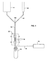
- the apparatus illustrated in Fig. 1 is particularly useful for magnetically separating certain types of target cells, such as lymphocytes, red blood cells, and/or macrophages from a blood sample.
- the illustrated apparatus includes a sample container 10 to contain the blood sample. Before or after the blood sample is introduced into container 10, it is mixed with magnetic particles, preferably the commercially-available magnetic microbeads, having a selective affinity to magnetically stain or label the target cells in the blood sample within container 10.
- magnetic particles preferably the commercially-available magnetic microbeads, having a selective affinity to magnetically stain or label the target cells in the blood sample within container 10.
- the apparatus further includes another container 11 which serves as a supply of a buffer liquid to be used in the magnetic separation process.
- the buffer liquid in container 11 may be any of the commercially-available buffer liquids, such as normal 1 saline solution, PBS, and the like.
- the apparatus illustrated in Fig. 1 further includes a feed tube 12 for feeding the buffer liquid from the buffer container 11 through a magnetizing station 13 to a receiving container 14.
- the feeding of the buffer liquid via feed tube 12 is effected by gravity and a vacuum.
- the two supply containers 10 and 11 are located above the receiving container 14; and the receiving container 14 includes a vacuum tube 15 communicating at one end with the interior of the receiving container, and at the opposite end with a vacuum source 16.
- the blood sample within the sample container 10 includes the magnetically-stained target cells as well as the non-targetted cells.
- the blood sample is introduced via line 17 into an input port 12a in the feed tube 12 at a location upstream of the magnetizing station 13.
- the feed tube is first filled with degassed buffer liquid from container 1, and a predetermined flow rate is effected.
- the flow rate is preferably less than one drop per second; a preferred flow rate is 6-8 drops per minute.
- Presetting the flow rate may be effected by controlling the vacuum source 16, or by controlling one or more valves as will be described more particularly below with respect to Fig. 2 .
- the buffer liquid from container 11 thus serves as a continuous liquid carrier for the magnetically-stained target cells and non-target cells in the blood sample introduced from container 10 via the input port 12a, as both the buffer liquid and the mixture, including the target cells and non-targetted cells therein, flow via the feed tube 12 through the magnetizing station 13.
- Magnets 18 at the magnetizing station 13 apply a magnetic field across the feed tube 12 sufficient to separate and retain the magnetically-stained target cells within the buffer liquid at the magnetizing station 13 as the buffer liquid, with the non-magnetized cells and other constituents of the blood sample, flows through the output end of the feed tube 12 into the receiving container 14.
- the receiving container 14 thus receives the buffer liquid together with the non-targetted cells of the blood sample, since the magnetically-stained target cells of the blood sample (including the magnetic particles mixed therein) are held in stasis by the magnetic flux produced by the magnets 18 in the magnetizing station 13.
- the contents of the receiving container 14 thus constitute the results of a depletion process performed on the original sample since these contents include all the original constituents of the sample except for the magnetically-stained target cells (and the magnetic particles added to the original sample in container 10) which are separated and retained in the magnetizing station 13. Accordingly, the contents of container 14 may be examined or used for diagnostic, research, or clinical purposes in the same manner as when using the results of any other corresponding depletion process performed on the original sample.
- this may be done by: (a) continuing to feed the buffer liquid through tube 12; (b) terminating the supply of the mixture from the sample container 10 and the application of the magnetic field at the magnetizing station 13; and (c) replacing the receiving container 14 with another receiving container (not shown) to receive the target cells which are flushed-out by the buffer liquid fed through the feed tube 12.
- Magnets 18 at the magnetizing station 13 may be permanent magnets which can be physically removed or moved away from the magnetizing station when flushing out the magnetically-separated target cells.
- these magnets 18 may be electromagnets electrically energized via connectors 19 ( Fig. 2 ) during the magnetic-separation phase, and electrically deenergized during the flushing-out phase.
- the buffer liquid supplied from the buffer container 11 provides a constant and continuous fluid volume, and thereby forms a continuous liquid carrier for all the constituents of the sample mixture supplied from the sample container 10. This is true both during the initial depletion stage, wherein the original sample depleted of the target cells is received within container 14, and also during the positive selection stage, wherein the target cells separated and retained in the magnetizing station 13 are flushed out by the buffer liquid into another receiving container.
- the buffer liquid thus continuously supports both the target cells and the non-targetted cells during both phases of the separation process such as to substantially decrease the possibility of damage or rupture of the cell membranes, as compared to the conventional MiniMACS process described above.
- the method illustrated in Fig. 1 is highly susceptible to automation to provide greater through-put capabilities and improved efficiency in the separation process.
- the separation device was prepared by filling and rinsing the feed tube 12 with degassed buffer from the buffer reservoir. Throughout the separation, the system remains filled with the degassed buffer.
- the stained lymphocyte mixture was introduced into the system by way of a 1ml. syringe (w/o the plunger) with a 0.4x13 needle inserted into a "piggyback site" in the tubing.
- the vacuum system maintained a steady flow rate of 6 drops per minute.
- the needle was removed and the system left to run until an additional 400 ⁇ l of buffer had flowed through the separation system. Flow was halted.
- the receiving tube was removed, labeled "A", and replaced with a second tube.
- B cells comprise 8-11% of the total lymphocyte population. Results of this separation yielded 8.8% B cells, demonstrating the ability to isolate a specific population with no change in the cell quality.
- CD19 microbeads (Miltenyi Biotec GmbH) to stain for B Lymphocytes, would be expected to produce a harvest of approximately 10% from the total lymphocyte population.
- the magnetic field was produced by permanent magnets of neodymium; the tubing was 0.80 mm infusion tubing; and the buffer liquid was of the following composition: 0.15 ml EDTA (Ethylenediarnine tetraacetic acid); 1.10 ml BSA 796 (Bovine serum albumin); 13.75 ml PBS (Phosphate Buffered Saline w/o calcium and magnesium); yielding 15.00 ml total buffer
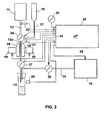
- Fig. 2 schematically illustrates the basic system of Fig. 1 but equipped with the main controls for automating the operation of the system.
- the system illustrated in Fig. 2 includes a microprocessor controller, generally designated 20, for controlling the overall operation of the system.
- the inputs to controller 20 include a flow selector 21 for presetting the flow rate of feed of the buffer liquid from the buffer container 11; an air bubble sensor 22 for sensing the presence of air bubbles in the buffer feed tube 12; and an air bubble sensor 23 for sensing the presence of air bubbles in the sample feed tube 17. These sensors protect the integrity of the constant fluid level by shutting down fluid flow (sensor 22 will close valve 27, and sensor 23 will close valve 28) if an air bubble is detected.
- Controller 20 also includes an input from a flow rate sensor 29 for sensing the flow into container 14.
- Controller 20 in turn controls the electromagnets 18 at the magnetizing station 13 via line 24 connected to their connectors 19, the vacuum source 16 via line 25 and/or a vacuum valve 26, the feed rate of the buffer liquid via valve 27 in the feed line 12, and the feed rate of the sample via valve 28 in the sample line 17.
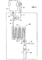
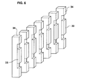
- Figs. 3-6 illustrate a preferred construction of the magnetic unit in the magnetizing station 13 according to the present invention to enable the magnetizing station to occupy a substantially longer flowpath of the buffer liquid carrying the sample, and thereby to increase the throughput and/or efficiency of the overall separation process.
- the magnetizing station 13 occupies a straight length of the feed tube 12
- the magnetizing station, therein designated 30, is constructed, to occupy an elongated, serpentine length of the feed tube 12.
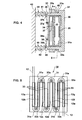
- the magnetizing station 30 includes a back mounting plate 31 and a front mounting plate 32 assembled together by pins 32a in plate 32 received with a friction fit in apertured posts 31a in plate 31.
- the back mounting plate 31 mounts a plurality of permanent magnets 33 each carried by a magnetizable core element 34; and similarly, the front mounting plate 32 mounts a plurality of permanent magnets 35 each carried by a magnetizable core element 36.
- the permanent magnets 33 and 35 are aligned with each other, and the magnetizable core elements 34 and 36 are aligned with each other, so that they define two closed magnetic circuits, one including air gaps AG 1 , AG 2 , and the other including air gaps AG 1 , AG 3 , each stretch of the feed tube 12 passes through all three air gaps AG 1 -AG 3 , such that the magnetic field produced by the permanent magnets is effective over a substantial length of the feed tube.
- the back mounting plate 31 is movably mounted by a pair of rocker arms 37, 38.
- Each rocker arm includes a pivotal mounting 37a, 38a to the back mounting plate 31, and another pivotal mounting 37b, 38b to a collar 39, 40 slidably received on pins 41, 42 projecting from a supporting surface 42.
- Collar 39 is slideably received on the upper pin 41, and collar 40 is slideably received on the lower pin 42 fixed to the supporting surface 43 below pin 41.
- the two collars 39, 40 are biassed outwardly by coiled springs 44, 45 on their respective pins 41, 43.
- the back plate 31 includes three apertured posts 31a at the upper end, and three such posts at the lower end in staggered relationship with respect to the posts at the upper end.
- the pins 32a in the front mounting plate 32 are correspondingly arranged so as to be received within the apertured posts 31a in plate 31.
- the feed tube 12 may be wound around the upper and lower posts 31a of the back plate 31 in a serpentine fashion ( Fig. 5 ), to produce downwardly-extending and upwardly-extending stretches 12a-g.
- the last downwardly-extending stretch 12g is connected to the receiving container 14 in Fig. 3 .
- each pair of magnets and core elements define three air gaps (AG 1 -AG 3 , Fig. 4 ) for each stretch 12a-12g of the feed tube, such that the magnetic field in the magnetizing station is effective over a considerable length of the feed tube.
- Pins 32a of the front plate 32 are dimensioned to produce a friction fit when the pins are received within the posts.
- Posts 31 are also dimensioned to define a space, shown at 46 ( Fig. 4 ), between the magnets 33, 35 carried by the two plates 31, 32 for receiving the respective stretch 12a-12g of the feed tube 12.
- the front plate 32 is applied by inserting the pins 32a through the posts 31a.
- the pins engage the collars 39, 40, moving them towards the fixed surface 43 against springs 44, 45.
- the back plate 31 is thus moved by rocker arms 37, 38 towards the front plate 37, to thereby firmly sandwich the respective stretches of the feed tube 12 between the two groups of magnets 33, 35.
- Fig. 7 illustrates an apparatus similarto that of Fig. 3 , except that the apparatus of Fig. 7 further includes a mixing chamber 100 at the input port 112a of the feed tube 112 for pre-mixing the sample mixture applied via inlet tube 110, and the buffer liquid applied via inlet 111, before being fed, via tube 112, to the magnetizing station 130.
- the apparatus in Fig. 7 further includes a pump 132, such as a peristaltic pump, in the outlet end of tube 112 for controlling the feeding of the liquid therefrom into the receiving container (14, Fig. 3 ).
- a pump 132 such as a peristaltic pump
- the magnetic field can be controlled according to the particular application to produce a predetermined field intensity.
- the magnetic air gap can be changed when using permanent magnets: and when using electromagnets, the current can be varied, e.g., via microprocessor 20 in Fig. 2 .
Landscapes
- Apparatus Associated With Microorganisms And Enzymes (AREA)
- Micro-Organisms Or Cultivation Processes Thereof (AREA)
- Investigating Or Analysing Biological Materials (AREA)
- Medicines Containing Material From Animals Or Micro-Organisms (AREA)
- Immobilizing And Processing Of Enzymes And Microorganisms (AREA)
- Sampling And Sample Adjustment (AREA)
Applications Claiming Priority (3)
| Application Number | Priority Date | Filing Date | Title |
|---|---|---|---|
| IL12451498 | 1998-05-17 | ||
| IL12451498A IL124514A (en) | 1998-05-17 | 1998-05-17 | Method and apparatus for magnetically separating selected particles, particularly biological cells |
| PCT/IL1999/000255 WO1999059694A1 (en) | 1998-05-17 | 1999-05-13 | Method and apparatus for magnetically separating selected particles, particularly biological cells |
Publications (3)
| Publication Number | Publication Date |
|---|---|
| EP1093393A1 EP1093393A1 (en) | 2001-04-25 |
| EP1093393A4 EP1093393A4 (en) | 2002-09-11 |
| EP1093393B1 true EP1093393B1 (en) | 2008-06-25 |
Family
ID=11071507
Family Applications (1)
| Application Number | Title | Priority Date | Filing Date |
|---|---|---|---|
| EP99921111A Expired - Lifetime EP1093393B1 (en) | 1998-05-17 | 1999-05-13 | Method and apparatus for magnetically separating selected particles, particularly biological cells |
Country Status (13)
| Country | Link |
|---|---|
| US (2) | US6482328B1 (enExample) |
| EP (1) | EP1093393B1 (enExample) |
| JP (1) | JP4713735B2 (enExample) |
| AT (1) | ATE399048T1 (enExample) |
| AU (1) | AU754781B2 (enExample) |
| BR (1) | BR9911023B1 (enExample) |
| CA (1) | CA2333299C (enExample) |
| DE (1) | DE69938968D1 (enExample) |
| DK (1) | DK1093393T3 (enExample) |
| ES (1) | ES2310037T3 (enExample) |
| IL (1) | IL124514A (enExample) |
| MX (1) | MXPA00011129A (enExample) |
| WO (1) | WO1999059694A1 (enExample) |
Families Citing this family (43)
| Publication number | Priority date | Publication date | Assignee | Title |
|---|---|---|---|---|
| JP4643008B2 (ja) * | 1999-01-18 | 2011-03-02 | プレシジョン・システム・サイエンス株式会社 | 磁性粒子を利用した濃縮装置およびその方法 |
| US6635181B2 (en) * | 2001-03-13 | 2003-10-21 | The Board Of Governors For Higher Education, State Of Rhode Island And Providence Plantations | Continuous, hybrid field-gradient device for magnetic colloid based separations |
| DE10127068A1 (de) * | 2001-05-23 | 2002-11-28 | Bio Medical Apherese Systeme G | Vorrichtung und Verfahren zum Inkubieren und Wiederabtrennen von Magnetteilchen in und von flüssige biologische Dispersionen |
| US20030095897A1 (en) * | 2001-08-31 | 2003-05-22 | Grate Jay W. | Flow-controlled magnetic particle manipulation |
| AU2003226075B2 (en) | 2002-04-12 | 2008-09-25 | Instrumentation Laboratory Company | Immunoassay probe |
| WO2004085668A2 (en) * | 2003-03-20 | 2004-10-07 | Northeastern Ohio Universities College Of Medecine | Self-contained assay device for rapid detection of biohazardous agents |
| FI20040159A0 (fi) * | 2003-10-20 | 2004-02-02 | Bio Mobile Oy | Magneettinen siirtomenetelmä, mikropartikkelien siirtolaite, ja reaktioyksikkö |
| US8211386B2 (en) | 2004-06-08 | 2012-07-03 | Biokit, S.A. | Tapered cuvette and method of collecting magnetic particles |
| US7403125B2 (en) * | 2005-05-06 | 2008-07-22 | Accuri Cytometers, Inc. | Flow cytometry system with bubble detection |
| US20080233630A1 (en) * | 2005-06-20 | 2008-09-25 | Young-Ho Kim | Apparatus and Method for Magnetically Separating Cells From Mixture |
| US7996188B2 (en) | 2005-08-22 | 2011-08-09 | Accuri Cytometers, Inc. | User interface for a flow cytometer system |
| US8303894B2 (en) * | 2005-10-13 | 2012-11-06 | Accuri Cytometers, Inc. | Detection and fluidic system of a flow cytometer |
| US8017402B2 (en) * | 2006-03-08 | 2011-09-13 | Accuri Cytometers, Inc. | Fluidic system for a flow cytometer |
| US7776268B2 (en) * | 2005-10-13 | 2010-08-17 | Accuri Cytometers, Inc. | User interface for a fluidic system of a flow cytometer |
| US7857005B2 (en) * | 2005-12-07 | 2010-12-28 | Accuri Cytometers, Inc. | Pulsation attenuator for a fluidic system |
| KR100992462B1 (ko) | 2006-01-11 | 2010-11-08 | 한국과학기술연구원 | 중력과 자기력의 차이를 이용한 생물학적 입자 분리 장치및 방법 |
| US7780916B2 (en) * | 2006-03-08 | 2010-08-24 | Accuri Cytometers, Inc. | Flow cytometer system with unclogging feature |
| US8283177B2 (en) * | 2006-03-08 | 2012-10-09 | Accuri Cytometers, Inc. | Fluidic system with washing capabilities for a flow cytometer |
| US7981661B2 (en) * | 2006-04-17 | 2011-07-19 | Accuri Cytometers, Inc. | Flow cytometer system with sheath and waste fluid measurement |
| US8715573B2 (en) * | 2006-10-13 | 2014-05-06 | Accuri Cytometers, Inc. | Fluidic system for a flow cytometer with temporal processing |
| WO2008048027A1 (en) * | 2006-10-16 | 2008-04-24 | Cellbio Co., Ltd | Apparatus and method for magnetically separating biolgical materials from mixture |
| US8445286B2 (en) | 2006-11-07 | 2013-05-21 | Accuri Cytometers, Inc. | Flow cell for a flow cytometer system |
| US7739060B2 (en) * | 2006-12-22 | 2010-06-15 | Accuri Cytometers, Inc. | Detection system and user interface for a flow cytometer system |
| US8432541B2 (en) * | 2007-12-17 | 2013-04-30 | Accuri Cytometers, Inc. | Optical system for a flow cytometer with an interrogation zone |
| US7947492B2 (en) * | 2008-08-20 | 2011-05-24 | Northeastern Ohio Universities College Of Medicine | Device improving the detection of a ligand |
| JP2010207133A (ja) | 2009-03-10 | 2010-09-24 | Sony Corp | 細胞分離方法 |
| US20110061471A1 (en) * | 2009-06-02 | 2011-03-17 | Rich Collin A | System and method of verification of a sample for a flow cytometer |
| US8507279B2 (en) | 2009-06-02 | 2013-08-13 | Accuri Cytometers, Inc. | System and method of verification of a prepared sample for a flow cytometer |
| CN102762712A (zh) * | 2010-01-21 | 2012-10-31 | 百赛普有限公司 | 稀有细胞的磁性分离 |
| WO2011106402A1 (en) | 2010-02-23 | 2011-09-01 | Accuri Cytometers, Inc. | Method and system for detecting fluorochromes in a flow cytometer |
| WO2011159708A1 (en) | 2010-06-14 | 2011-12-22 | Accuri Cytometers, Inc. | System and method for creating a flow cytometer network |
| WO2012061155A2 (en) | 2010-10-25 | 2012-05-10 | Accuri Cytometers, Inc. | Systems and user interface for collecting a data set in a flow cytometer |
| US8528427B2 (en) | 2010-10-29 | 2013-09-10 | Becton, Dickinson And Company | Dual feedback vacuum fluidics for a flow-type particle analyzer |
| WO2013095867A1 (en) * | 2011-12-21 | 2013-06-27 | Becton, Dickinson And Company | Flow cytometric systems for sterile separation of magnetically labeled sample components |
| US9517474B2 (en) | 2012-05-18 | 2016-12-13 | University Of Georgia Research Foundation, Inc. | Devices and methods for separating particles |
| CN103773682B (zh) * | 2014-01-23 | 2015-09-30 | 张利峰 | 细胞磁分选系统、分选装置和处理设备 |
| US20150284862A1 (en) * | 2014-04-07 | 2015-10-08 | John Staley Brookshire | Continuous Flow Process for Producing Storable Consumable Magnascent Iodine |
| CN103949341A (zh) * | 2014-04-29 | 2014-07-30 | 东南大学 | 一种全自动生物样本处理装置 |
| SG10202110399WA (en) * | 2015-06-05 | 2021-11-29 | Novartis Ag | Flow-through paramagnetic particle-based cell separation and paramagnetic particle removal |
| US10676719B2 (en) | 2015-07-31 | 2020-06-09 | University Of Georgia Research Foundation, Inc. | Devices and methods for separating particles |
| US10189029B2 (en) * | 2016-06-30 | 2019-01-29 | United Arab Emirates University | Magnetic particle separator |
| CN116943860A (zh) * | 2016-10-31 | 2023-10-27 | 美国安进公司 | 纯化系统和方法 |
| WO2019194417A1 (ko) * | 2018-04-04 | 2019-10-10 | 광주과학기술원 | 미생물 농축 소자 |
Citations (3)
| Publication number | Priority date | Publication date | Assignee | Title |
|---|---|---|---|---|
| US4738773A (en) * | 1985-06-22 | 1988-04-19 | Bayer Aktiengesellschaft | Separator for magnetic particles from liquid phase |
| US4904391A (en) * | 1985-10-09 | 1990-02-27 | Freeman Richard B | Method and apparatus for removal of cells from bone marrow |
| US5711871A (en) * | 1995-02-27 | 1998-01-27 | Miltenyi Biotec Gmbh | Magnetic separation apparatus |
Family Cites Families (4)
| Publication number | Priority date | Publication date | Assignee | Title |
|---|---|---|---|---|
| US4710472A (en) * | 1985-09-25 | 1987-12-01 | The United States Of America As Represented By The Secretary Of The Navy | Magnetic separation device |
| CA1335181C (en) * | 1988-10-11 | 1995-04-11 | R. Alan Hardwick | System for selective cell separation from cell concentrate |
| US5536475A (en) * | 1988-10-11 | 1996-07-16 | Baxter International Inc. | Apparatus for magnetic cell separation |
| AU708810B2 (en) * | 1994-03-14 | 1999-08-12 | Nexell Therapeutics Inc. | Method and apparatus for semi-automated cell separation |
-
1998
- 1998-05-17 IL IL12451498A patent/IL124514A/en not_active IP Right Cessation
-
1999
- 1999-05-13 WO PCT/IL1999/000255 patent/WO1999059694A1/en not_active Ceased
- 1999-05-13 JP JP2000549351A patent/JP4713735B2/ja not_active Expired - Lifetime
- 1999-05-13 MX MXPA00011129A patent/MXPA00011129A/es active IP Right Grant
- 1999-05-13 CA CA002333299A patent/CA2333299C/en not_active Expired - Fee Related
- 1999-05-13 DK DK99921111T patent/DK1093393T3/da active
- 1999-05-13 ES ES99921111T patent/ES2310037T3/es not_active Expired - Lifetime
- 1999-05-13 US US09/700,218 patent/US6482328B1/en not_active Expired - Lifetime
- 1999-05-13 AU AU38452/99A patent/AU754781B2/en not_active Ceased
- 1999-05-13 BR BRPI9911023-7A patent/BR9911023B1/pt not_active IP Right Cessation
- 1999-05-13 EP EP99921111A patent/EP1093393B1/en not_active Expired - Lifetime
- 1999-05-13 AT AT99921111T patent/ATE399048T1/de not_active IP Right Cessation
- 1999-05-13 DE DE69938968T patent/DE69938968D1/de not_active Expired - Lifetime
-
2002
- 2002-10-30 US US10/283,100 patent/US20030062314A1/en not_active Abandoned
Patent Citations (3)
| Publication number | Priority date | Publication date | Assignee | Title |
|---|---|---|---|---|
| US4738773A (en) * | 1985-06-22 | 1988-04-19 | Bayer Aktiengesellschaft | Separator for magnetic particles from liquid phase |
| US4904391A (en) * | 1985-10-09 | 1990-02-27 | Freeman Richard B | Method and apparatus for removal of cells from bone marrow |
| US5711871A (en) * | 1995-02-27 | 1998-01-27 | Miltenyi Biotec Gmbh | Magnetic separation apparatus |
Also Published As
| Publication number | Publication date |
|---|---|
| IL124514A0 (en) | 1998-12-06 |
| HK1037151A1 (en) | 2002-02-01 |
| CA2333299A1 (en) | 1999-11-25 |
| DE69938968D1 (de) | 2008-08-07 |
| WO1999059694A1 (en) | 1999-11-25 |
| BR9911023A (pt) | 2001-09-25 |
| US6482328B1 (en) | 2002-11-19 |
| EP1093393A4 (en) | 2002-09-11 |
| DK1093393T3 (da) | 2008-10-06 |
| CA2333299C (en) | 2007-09-18 |
| AU3845299A (en) | 1999-12-06 |
| IL124514A (en) | 2002-02-10 |
| JP2002515319A (ja) | 2002-05-28 |
| ATE399048T1 (de) | 2008-07-15 |
| AU754781B2 (en) | 2002-11-28 |
| EP1093393A1 (en) | 2001-04-25 |
| MXPA00011129A (es) | 2002-08-06 |
| US20030062314A1 (en) | 2003-04-03 |
| BR9911023B1 (pt) | 2009-12-01 |
| ES2310037T3 (es) | 2008-12-16 |
| JP4713735B2 (ja) | 2011-06-29 |
Similar Documents
| Publication | Publication Date | Title |
|---|---|---|
| EP1093393B1 (en) | Method and apparatus for magnetically separating selected particles, particularly biological cells | |
| CN1263548C (zh) | 混合物成分的连续磁性分离 | |
| EP0869838B1 (en) | Magnetic separation apparatus | |
| US5968820A (en) | Method for magnetically separating cells into fractionated flow streams | |
| US6120735A (en) | Fractional cell sorter | |
| US6159378A (en) | Apparatus and method for handling magnetic particles in a fluid | |
| JPS61293562A (ja) | 磁化可能粒子の磁気的除去のための分離機 | |
| HK1037151B (en) | Method and apparatus for magnetically separating selected particles, particularly biological cells | |
| US20240393324A1 (en) | Method for Magnetically Sorting Biological Objects | |
| CN223409620U (zh) | 一种基于磁性纳米粒子的多通道细胞分离装置 | |
| HK1032554B (en) | Continuous magnetic separation of components from a mixture | |
| JPS6125040A (ja) | 微小粒子分析/分離装置におけるサンプル供給方法およびその装置 |
Legal Events
| Date | Code | Title | Description |
|---|---|---|---|
| PUAI | Public reference made under article 153(3) epc to a published international application that has entered the european phase |
Free format text: ORIGINAL CODE: 0009012 |
|
| 17P | Request for examination filed |
Effective date: 20001212 |
|
| AK | Designated contracting states |
Kind code of ref document: A1 Designated state(s): AT BE CH CY DE DK ES FI FR GB GR IE IT LI LU MC NL PT SE |
|
| AX | Request for extension of the european patent |
Free format text: AL PAYMENT 20001212;LT PAYMENT 20001212;LV PAYMENT 20001212;MK PAYMENT 20001212;RO PAYMENT 20001212;SI PAYMENT 20001212 |
|
| A4 | Supplementary search report drawn up and despatched |
Effective date: 20020729 |
|
| AK | Designated contracting states |
Kind code of ref document: A4 Designated state(s): AT BE CH CY DE DK ES FI FR GB GR IE IT LI LU MC NL PT SE |
|
| RIC1 | Information provided on ipc code assigned before grant |
Free format text: 7B 01D 35/06 A, 7B 03C 1/00 B, 7B 03C 1/005 B, 7B 03C 1/01 B, 7B 03C 1/28 B, 7G 01N 33/543 B |
|
| RAP1 | Party data changed (applicant data changed or rights of an application transferred) |
Owner name: INNOVATECH MEDICAL EQUIPMENT LTD. |
|
| RIN1 | Information on inventor provided before grant (corrected) |
Inventor name: LAMISH, AHARON Inventor name: KLEIN, OFER Inventor name: DAVIDSON, CHAIM |
|
| 17Q | First examination report despatched |
Effective date: 20040402 |
|
| RAP1 | Party data changed (applicant data changed or rights of an application transferred) |
Owner name: BIOCEP LTD. |
|
| GRAP | Despatch of communication of intention to grant a patent |
Free format text: ORIGINAL CODE: EPIDOSNIGR1 |
|
| GRAS | Grant fee paid |
Free format text: ORIGINAL CODE: EPIDOSNIGR3 |
|
| GRAA | (expected) grant |
Free format text: ORIGINAL CODE: 0009210 |
|
| AK | Designated contracting states |
Kind code of ref document: B1 Designated state(s): AT BE CH CY DE DK ES FI FR GB GR IE IT LI LU MC NL PT SE |
|
| AX | Request for extension of the european patent |
Extension state: AL LT LV MK RO SI |
|
| REG | Reference to a national code |
Ref country code: GB Ref legal event code: FG4D |
|
| REG | Reference to a national code |
Ref country code: CH Ref legal event code: EP |
|
| REF | Corresponds to: |
Ref document number: 69938968 Country of ref document: DE Date of ref document: 20080807 Kind code of ref document: P |
|
| REG | Reference to a national code |
Ref country code: IE Ref legal event code: FG4D |
|
| PG25 | Lapsed in a contracting state [announced via postgrant information from national office to epo] |
Ref country code: FI Free format text: LAPSE BECAUSE OF FAILURE TO SUBMIT A TRANSLATION OF THE DESCRIPTION OR TO PAY THE FEE WITHIN THE PRESCRIBED TIME-LIMIT Effective date: 20080625 |
|
| PG25 | Lapsed in a contracting state [announced via postgrant information from national office to epo] |
Ref country code: AT Free format text: LAPSE BECAUSE OF FAILURE TO SUBMIT A TRANSLATION OF THE DESCRIPTION OR TO PAY THE FEE WITHIN THE PRESCRIBED TIME-LIMIT Effective date: 20080625 |
|
| REG | Reference to a national code |
Ref country code: HK Ref legal event code: GR Ref document number: 1037151 Country of ref document: HK |
|
| REG | Reference to a national code |
Ref country code: ES Ref legal event code: FG2A Ref document number: 2310037 Country of ref document: ES Kind code of ref document: T3 |
|
| PG25 | Lapsed in a contracting state [announced via postgrant information from national office to epo] |
Ref country code: SE Free format text: LAPSE BECAUSE OF FAILURE TO SUBMIT A TRANSLATION OF THE DESCRIPTION OR TO PAY THE FEE WITHIN THE PRESCRIBED TIME-LIMIT Effective date: 20080925 Ref country code: PT Free format text: LAPSE BECAUSE OF FAILURE TO SUBMIT A TRANSLATION OF THE DESCRIPTION OR TO PAY THE FEE WITHIN THE PRESCRIBED TIME-LIMIT Effective date: 20081125 |
|
| PG25 | Lapsed in a contracting state [announced via postgrant information from national office to epo] |
Ref country code: BE Free format text: LAPSE BECAUSE OF FAILURE TO SUBMIT A TRANSLATION OF THE DESCRIPTION OR TO PAY THE FEE WITHIN THE PRESCRIBED TIME-LIMIT Effective date: 20080625 |
|
| PLBE | No opposition filed within time limit |
Free format text: ORIGINAL CODE: 0009261 |
|
| STAA | Information on the status of an ep patent application or granted ep patent |
Free format text: STATUS: NO OPPOSITION FILED WITHIN TIME LIMIT |
|
| 26N | No opposition filed |
Effective date: 20090326 |
|
| PG25 | Lapsed in a contracting state [announced via postgrant information from national office to epo] |
Ref country code: MC Free format text: LAPSE BECAUSE OF NON-PAYMENT OF DUE FEES Effective date: 20090531 |
|
| PG25 | Lapsed in a contracting state [announced via postgrant information from national office to epo] |
Ref country code: GR Free format text: LAPSE BECAUSE OF FAILURE TO SUBMIT A TRANSLATION OF THE DESCRIPTION OR TO PAY THE FEE WITHIN THE PRESCRIBED TIME-LIMIT Effective date: 20080926 |
|
| PG25 | Lapsed in a contracting state [announced via postgrant information from national office to epo] |
Ref country code: LU Free format text: LAPSE BECAUSE OF NON-PAYMENT OF DUE FEES Effective date: 20090513 |
|
| PG25 | Lapsed in a contracting state [announced via postgrant information from national office to epo] |
Ref country code: CY Free format text: LAPSE BECAUSE OF FAILURE TO SUBMIT A TRANSLATION OF THE DESCRIPTION OR TO PAY THE FEE WITHIN THE PRESCRIBED TIME-LIMIT Effective date: 20080625 |
|
| REG | Reference to a national code |
Ref country code: FR Ref legal event code: PLFP Year of fee payment: 18 |
|
| PGFP | Annual fee paid to national office [announced via postgrant information from national office to epo] |
Ref country code: NL Payment date: 20160510 Year of fee payment: 18 |
|
| PGFP | Annual fee paid to national office [announced via postgrant information from national office to epo] |
Ref country code: IE Payment date: 20160509 Year of fee payment: 18 Ref country code: GB Payment date: 20160511 Year of fee payment: 18 Ref country code: CH Payment date: 20160511 Year of fee payment: 18 Ref country code: DE Payment date: 20160510 Year of fee payment: 18 Ref country code: ES Payment date: 20160426 Year of fee payment: 18 |
|
| PGFP | Annual fee paid to national office [announced via postgrant information from national office to epo] |
Ref country code: DK Payment date: 20160510 Year of fee payment: 18 Ref country code: IT Payment date: 20160524 Year of fee payment: 18 Ref country code: FR Payment date: 20160426 Year of fee payment: 18 |
|
| REG | Reference to a national code |
Ref country code: DE Ref legal event code: R119 Ref document number: 69938968 Country of ref document: DE |
|
| REG | Reference to a national code |
Ref country code: CH Ref legal event code: PL |
|
| REG | Reference to a national code |
Ref country code: DK Ref legal event code: EBP Effective date: 20170531 |
|
| REG | Reference to a national code |
Ref country code: NL Ref legal event code: MM Effective date: 20170601 |
|
| GBPC | Gb: european patent ceased through non-payment of renewal fee |
Effective date: 20170513 |
|
| REG | Reference to a national code |
Ref country code: IE Ref legal event code: MM4A |
|
| PG25 | Lapsed in a contracting state [announced via postgrant information from national office to epo] |
Ref country code: CH Free format text: LAPSE BECAUSE OF NON-PAYMENT OF DUE FEES Effective date: 20170531 Ref country code: LI Free format text: LAPSE BECAUSE OF NON-PAYMENT OF DUE FEES Effective date: 20170531 |
|
| REG | Reference to a national code |
Ref country code: FR Ref legal event code: ST Effective date: 20180131 |
|
| PG25 | Lapsed in a contracting state [announced via postgrant information from national office to epo] |
Ref country code: NL Free format text: LAPSE BECAUSE OF NON-PAYMENT OF DUE FEES Effective date: 20170601 |
|
| PG25 | Lapsed in a contracting state [announced via postgrant information from national office to epo] |
Ref country code: IE Free format text: LAPSE BECAUSE OF NON-PAYMENT OF DUE FEES Effective date: 20170513 Ref country code: DE Free format text: LAPSE BECAUSE OF NON-PAYMENT OF DUE FEES Effective date: 20171201 Ref country code: GB Free format text: LAPSE BECAUSE OF NON-PAYMENT OF DUE FEES Effective date: 20170513 Ref country code: DK Free format text: LAPSE BECAUSE OF NON-PAYMENT OF DUE FEES Effective date: 20170531 |
|
| PG25 | Lapsed in a contracting state [announced via postgrant information from national office to epo] |
Ref country code: IT Free format text: LAPSE BECAUSE OF NON-PAYMENT OF DUE FEES Effective date: 20170513 Ref country code: FR Free format text: LAPSE BECAUSE OF NON-PAYMENT OF DUE FEES Effective date: 20170531 |
|
| REG | Reference to a national code |
Ref country code: ES Ref legal event code: FD2A Effective date: 20180629 |
|
| PG25 | Lapsed in a contracting state [announced via postgrant information from national office to epo] |
Ref country code: ES Free format text: LAPSE BECAUSE OF NON-PAYMENT OF DUE FEES Effective date: 20170514 |