EP1093105A1 - Illuminating device and display device provided with the device - Google Patents
Illuminating device and display device provided with the device Download PDFInfo
- Publication number
- EP1093105A1 EP1093105A1 EP00905396A EP00905396A EP1093105A1 EP 1093105 A1 EP1093105 A1 EP 1093105A1 EP 00905396 A EP00905396 A EP 00905396A EP 00905396 A EP00905396 A EP 00905396A EP 1093105 A1 EP1093105 A1 EP 1093105A1
- Authority
- EP
- European Patent Office
- Prior art keywords
- reflecting plate
- light source
- reflecting
- illumination
- illuminating unit
- Prior art date
- Legal status (The legal status is an assumption and is not a legal conclusion. Google has not performed a legal analysis and makes no representation as to the accuracy of the status listed.)
- Withdrawn
Links
Images


Classifications
-
- G—PHYSICS
- G02—OPTICS
- G02B—OPTICAL ELEMENTS, SYSTEMS OR APPARATUS
- G02B6/00—Light guides; Structural details of arrangements comprising light guides and other optical elements, e.g. couplings
- G02B6/0001—Light guides; Structural details of arrangements comprising light guides and other optical elements, e.g. couplings specially adapted for lighting devices or systems
- G02B6/0011—Light guides; Structural details of arrangements comprising light guides and other optical elements, e.g. couplings specially adapted for lighting devices or systems the light guides being planar or of plate-like form
- G02B6/0013—Means for improving the coupling-in of light from the light source into the light guide
- G02B6/0023—Means for improving the coupling-in of light from the light source into the light guide provided by one optical element, or plurality thereof, placed between the light guide and the light source, or around the light source
- G02B6/0026—Wavelength selective element, sheet or layer, e.g. filter or grating
-
- G—PHYSICS
- G02—OPTICS
- G02B—OPTICAL ELEMENTS, SYSTEMS OR APPARATUS
- G02B6/00—Light guides; Structural details of arrangements comprising light guides and other optical elements, e.g. couplings
- G02B6/0001—Light guides; Structural details of arrangements comprising light guides and other optical elements, e.g. couplings specially adapted for lighting devices or systems
- G02B6/0011—Light guides; Structural details of arrangements comprising light guides and other optical elements, e.g. couplings specially adapted for lighting devices or systems the light guides being planar or of plate-like form
- G02B6/0013—Means for improving the coupling-in of light from the light source into the light guide
- G02B6/0023—Means for improving the coupling-in of light from the light source into the light guide provided by one optical element, or plurality thereof, placed between the light guide and the light source, or around the light source
- G02B6/0031—Reflecting element, sheet or layer
-
- G—PHYSICS
- G02—OPTICS
- G02B—OPTICAL ELEMENTS, SYSTEMS OR APPARATUS
- G02B6/00—Light guides; Structural details of arrangements comprising light guides and other optical elements, e.g. couplings
- G02B6/0001—Light guides; Structural details of arrangements comprising light guides and other optical elements, e.g. couplings specially adapted for lighting devices or systems
- G02B6/0011—Light guides; Structural details of arrangements comprising light guides and other optical elements, e.g. couplings specially adapted for lighting devices or systems the light guides being planar or of plate-like form
- G02B6/0033—Means for improving the coupling-out of light from the light guide
- G02B6/005—Means for improving the coupling-out of light from the light guide provided by one optical element, or plurality thereof, placed on the light output side of the light guide
- G02B6/0055—Reflecting element, sheet or layer
-
- G—PHYSICS
- G02—OPTICS
- G02F—OPTICAL DEVICES OR ARRANGEMENTS FOR THE CONTROL OF LIGHT BY MODIFICATION OF THE OPTICAL PROPERTIES OF THE MEDIA OF THE ELEMENTS INVOLVED THEREIN; NON-LINEAR OPTICS; FREQUENCY-CHANGING OF LIGHT; OPTICAL LOGIC ELEMENTS; OPTICAL ANALOGUE/DIGITAL CONVERTERS
- G02F1/00—Devices or arrangements for the control of the intensity, colour, phase, polarisation or direction of light arriving from an independent light source, e.g. switching, gating or modulating; Non-linear optics
- G02F1/01—Devices or arrangements for the control of the intensity, colour, phase, polarisation or direction of light arriving from an independent light source, e.g. switching, gating or modulating; Non-linear optics for the control of the intensity, phase, polarisation or colour
- G02F1/13—Devices or arrangements for the control of the intensity, colour, phase, polarisation or direction of light arriving from an independent light source, e.g. switching, gating or modulating; Non-linear optics for the control of the intensity, phase, polarisation or colour based on liquid crystals, e.g. single liquid crystal display cells
- G02F1/133—Constructional arrangements; Operation of liquid crystal cells; Circuit arrangements
- G02F1/1333—Constructional arrangements; Manufacturing methods
- G02F1/1335—Structural association of cells with optical devices, e.g. polarisers or reflectors
- G02F1/1336—Illuminating devices
- G02F1/133615—Edge-illuminating devices, i.e. illuminating from the side
-
- G—PHYSICS
- G02—OPTICS
- G02B—OPTICAL ELEMENTS, SYSTEMS OR APPARATUS
- G02B6/00—Light guides; Structural details of arrangements comprising light guides and other optical elements, e.g. couplings
- G02B6/0001—Light guides; Structural details of arrangements comprising light guides and other optical elements, e.g. couplings specially adapted for lighting devices or systems
- G02B6/0011—Light guides; Structural details of arrangements comprising light guides and other optical elements, e.g. couplings specially adapted for lighting devices or systems the light guides being planar or of plate-like form
- G02B6/0033—Means for improving the coupling-out of light from the light guide
- G02B6/0035—Means for improving the coupling-out of light from the light guide provided on the surface of the light guide or in the bulk of it
- G02B6/0038—Linear indentations or grooves, e.g. arc-shaped grooves or meandering grooves, extending over the full length or width of the light guide
Definitions
- the present invention relates to a backlight-type or Front-type illuminating unit and a display unit having such an illuminating unit.
- a liquid crystal display unit built with a transmissive-type liquid crystal display panel it is the conventional practice to adopt an illuminating method known as the backlight type, i.e., an illuminating method of causing panel display by the light irradiated from an illuminating unit provided on the back side of the liquid crystal display panel.
- Backlight-type illuminating unites are broadly divided into the direct backlight-type and the edge light-backlight type ones.
- the direct backlight-type illuminating unit has a configuration in which a plurality of fluorescent tubes arranged in parallel on the back side of a liquid crystal display panel are used as light sources, and the back side of these fluorescent tubes is further covered with a translucent reflecting plate.
- the edge-light backlight-type illuminating unit is therefore proposed to solve the above-mentioned problems.
- fluorescent tubes 50 are provided along the edge of a light guide plate 51, and a diffuser 52 is printed on the light guide plate 51 in response to the distance from the fluorescent tubes 50 so as to achieve uniform illuminating beams to the display panel 53.
- a reflecting plate 54 is provided under the light guide plate 51 to improve the utilization rate of light.
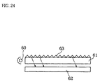
- an illuminating method known as the front light method i.e., the illuminating method of causing panel display with the light irradiated from an irradiating unit provided in front of the liquid crystal display panel is commonly adopted. More specifically, as shown in Fig. 24, the fluorescent lamps 60 are provided along an edge of the light guide plate 61, and the concave notches 63 are cut on the light guide plate 61 in response to the distance from the fluorescent lamps 60 so as to achieve uniformity of the illuminating light beams to the liquid crystal display panel 62.
- the present invention has an object to provide an illuminating unit which permits achievement of a smaller thickness and a reduced weight by eliminating a light guide plate, and to provide a display unit provided with such an illuminating unit.
- the invention of the claim 1 of the present invention provides an illuminating unit to illuminate an object of illumination, comprising a light source and a reflecting plate, which reflects an incident light from the light source, and directs the reflected light to the object of illumination, wherein the light source is arranged in the proximity of an end of the reflecting plate.
- an illuminating unit is composed achieving a smaller thickness and a reduced weight by eliminating a light guide plate.
- the illuminating unit of this invention is applicable to both the front light type and the backlight type.
- the illuminating unit of this invention is applicable, not only limited, for example, to an illuminating unit of a liquid crystal display unit, but also to the illuminating unites in a wide range including an illuminating unit for the purpose of illuminating the exhibits in a show window.
- the invention of the claim 2 provides an illuminating unit according to the claim 1, wherein the light source is arranged in the proximity of an end of the reflecting plate.
- the invention of the claim 3 provides an illuminating unit according to the claim 1, wherein the above said light sources are arranged in the proximity of both ends of the reflecting plate.
- the light source may be arranged on the reflecting surface of the reflecting plate.
- the invention of the claim 5 provides an illuminating unit according to the claim 4, wherein the light source is arranged in- the proximity of the center of the reflecting surface, and bends in a direction in which the more distant the said reflecting plate is from the light source, the more nearer it approaches the object of illumination.
- the aforementioned configuration of the illuminating unit in which the reflecting plate bends requires only a slight extent of bending of the reflecting plate even for the same area of the object of illumination, and the reflecting plate suffices to have a thickness of about a half. This permits reduction of the thickness of the illuminating unit in this invention.
- the invention of the claim 6 provides an illuminating unit of the backlight type, arranged behind an object of illumination, comprising a light source, and a reflecting plate, arranged opposite to the back surfaces of the object of illumination, which reflects an incident light from the light source and directs the reflected light to the object of illumination, wherein the light source is arranged in the proximity of an end of the reflecting plate.
- the invention of the claim 7 provides an illuminating unit according to the claim 6, wherein the reflecting plate is subjected to a reflecting angle adjusting treatment so that the incident angle of the reflected light entering the object of illumination becomes smaller accordingly as it becomes more distant from the light source so as to uniformly illuminate the object of illumination.
- the above-mentioned configuration makes it possible to cause gradual increase in the degree of condensation of the light directed toward the object of illumination accordingly as the distance from the light source becomes longer.
- the light has a high light intensity but a small degree of condensation at the portions of the object of illumination near the light source, whereas at the portions distant from the light source, the light has a low light intensity but a large degree of condensation. Consequently, this averages the illuminating light as a whole, thus permitting illumination of the object of illumination substantially to be uniform. It is thus possible to prevent the occurrence of display non-uniformity caused by attenuation of the light to be irradiated onto the object of illumination accordingly as the distance from the light source becomes longer.
- the invention of the claim 8 provides an illuminating unit according to the claim 7, wherein the reflecting angle adjusting treatment is to cause the reflecting plate to bend in a direction in which the more distant the said reflecting plate is from the light source, the more nearer it approaches the object of illumination.
- the reflecting angle on the reflecting plate becomes larger accordingly as the distance from the light source becomes longer. It is therefore become possible to ensure uniform illumination of the object of illumination.
- the uniformity of illumination is further improved than that in the invention of the claim 8.
- the reflecting angle on the reflecting plate becomes larger accordingly as the distance from the light source becomes longer. It is therefore possible to ensure uniform illumination of the object of illumination.
- the reflecting angle on the reflecting plate becomes larger accordingly as the distance from the light source becomes longer. It is therefore become possible to ensure uniform illumination of the object of illumination.
- the invention of the claim 13 provides an illuminating unit according to the claim 7, wherein the reflecting angle adjusting treatment is such that the reflecting plate bends in a direction in which the more distant the said reflecting plate is from the light source, the more nearer it approaches the object of illumination, and a number of the micro-projections each having a slant surface reflecting the incident light from the light source are formed on the reflecting plate, and these micro-projections are arranged so that the distribution density thereof becomes gradually larger accordingly as the distance from the light source becomes longer.
- the invention of the claim 14 provides an illuminating unit according to the claim 6, wherein the illuminating unit has optical means which directs the light from the light source substantially in parallel to the reflecting plate.
- the aforementioned configuration improves parallelism of the irradiation light onto the reflecting plate, and thereby improves the uniformity of illumination.
- the invention of the claim 15 provides an illuminating unit according to the claim 14, wherein a diffusing plate is provided between the reflecting plate and the object of illumination.
- the light reflected from the reflecting plate is diffused upon passing through the diffusing plate, thus achieving uniform distribution of the light. As the result, it improves the uniformity of illumination.
- the invention of the claim 17 provides a display unit built by use of the illuminating unit according to the claim 6, wherein a transmissive-type liquid crystal display panel is arranged as an object of illumination on the surface side of the reflecting plate of the illuminating unit, and the liquid crystal display panel is a liquid crystal display panel of the diffusion display mode in which the mode is switched over between a transmissive state and a diffusion state on the basis of the presence or absence of impression of a voltage.
- the above-mentioned configuration permits the configuration of a display unit of a diffusion display mode that has achieved the reduction of thickness and weight.
- the invention of the claim 18 provides a display unit built by use of the illuminating unit according to the claim 7, wherein a transmissive-type liquid crystal display panel is arranged as an object of illumination on the surface side of the reflecting plate of the illuminating unit, and the liquid crystal display panel is a liquid crystal display panel of the diffusion display mode in which the mode is switched over between a transmissive state and a diffusion state on the basis of the presence or absence of impression of a voltage; and the reflecting angle adjusting treatment of the reflecting plate is suitable for irradiating a diagonal light of a high parallelism to the liquid crystal display panel, in addition to the uniformity of illumination.
- the invention of the claim 20 provides a display unit according to the claim 18, wherein the display unit has optical means which converts the diffusing light from the light source substantially into a parallel light and directs the same to the reflecting plate.
- the invention of the claim 21 provides a front-light-type illuminating unit arranged on the front side of an object of illumination, comprising a light source and a reflecting plate reflecting an incident light from the light source and directing the reflected light to an object of illumination; and supporting means that supports a base end of the reflecting plate in a rotatable manner so as to make the angle between the reflecting plate and the object of illumination adjustable, wherein the light source is provided on the leading end side of the reflecting plate.
- the difference in optical path length between the reflected light beams irradiated onto the object of illumination via the reflecting plate, and further, the difference in optical path length between the light irradiated onto the object of illumination directly from the light source and the reflected light will largely be reduced as compared with the conventional cases. This improves the uniformity of illumination.
- the optical path length of the light irradiated onto the object of illumination from the light source via the reflecting plate is increased from that in the configuration in which the light source is provided on the reflecting plate side.
- the invention of the claim 23 provide an illuminating unit according to the claim 21, wherein, when the reflecting plate is at a position opposite to the object of illumination so as to ensure uniform illumination of the object of illumination, the reflecting plate is subjected to a reflecting angle adjusting treatment so that the incident angle of the reflected light entering the object of illumination becomes smaller as it moves toward the base end of the reflecting plate from the leading end.
- uniformity of the illumination is improved not only through adjustment of the angle of the reflecting plate, but also through a change in the reflecting angle.
- the invention of the claim 24 provides an illuminating unit according to the claim 22, wherein, when the reflecting plate is at a position opposite to the object of illumination so as to ensure the uniform illumination of the object of illumination, the reflecting plate is subjected to a reflecting angle adjusting treatment so that the incident angle of the reflected light entering the object of illumination becomes smaller as it moves toward the base end of the reflecting plate from the leading end.
- uniformity of the illumination is improved not only through adjustment of the angle of the reflecting plate, but also through a change in the reflecting angle.
- the invention of the claim 25 provides an illuminating unit according to the claim 23, wherein the reflecting angle adjusting treatment is such that the reflecting plate bends in a direction in which the nearer the said reflecting plate approaches the base end, the nearer it approaches the light source.
- the reflecting angle on the reflecting plate becomes larger according as the distance from the light source becomes longer. This makes it possible to uniformly illuminate the object of illumination.
- the invention of the claim 26 provides an illuminating unit according to the claim 24, wherein the reflecting angle adjusting treatment is such that the reflecting plate bends in a direction in which the nearer the said reflecting plate approaches the base end, the nearer it approaches the light source.
- the reflecting angle on the reflecting plate becomes larger accordingly as the distance from the light source becomes longer. This makes it possible to uniformly illuminate the object of illumination.
- the invention of the claim 27 provides an illuminating unit according to the claim 25, wherein the reflecting plate bends in a parabola shape.
- the invention of the claim 28 provides an illuminating unit according to the claim 26, wherein the reflecting plate bends in a parabola shape.
- the invention of the claim 29 provides an illuminating unit according to the claim 23, wherein the reflecting angle adjusting treatment is such that a number of the micro-projections each having a slant surface reflecting the incident light from the light source are formed on the reflecting plate, and these micro-projections are arranged so that the inclination angle of the slant surface becomes gradually larger accordingly as it becomes more distant from the light source.
- the reflecting angle on the reflecting plate becomes larger accordingly as the distance from the light source becomes longer. This makes it possible to uniformly illuminate the object of illumination.
- the invention of the claim 30 provides an illuminating unit according to the claim 24, wherein the reflecting angle adjusting treatment is such that a number of the micro-projections each having a slant surface reflecting the incident light from the light source are formed on the reflecting plate, and these micro-projections are arranged so that the inclination angle of the slant surface becomes gradually larger accordingly as it becomes more distant from the light source.
- the reflecting angle on the reflecting plate becomes larger accordingly as the distance from the light source becomes longer. This makes it possible to uniformly illuminate the object of illumination.
- the invention of the claim 31 provides an illuminating unit according to the claim 23, wherein the reflecting angle adjusting treatment is such that a number of the micro-projections each having a slant surface reflecting the incident light from the light source are formed on the reflecting plate, and said micro-projections are arranged so that the distribution density becomes gradually larger accordingly as the distance from the light source becomes longer.
- the reflecting angle on the reflecting plate becomes larger according as the distance from the light source becomes longer. This makes it possible to uniformly illuminate the object of illumination.
- the invention of the claim 32 provides an illuminating unit according to the claim 24, wherein the reflecting angle adjusting treatment is such that a number of the micro-projections each having a slant surface reflecting the incident light from the light source are formed on the reflecting plate, and these micro-projections are arranged so that the distribution density becomes gradually larger accordingly as the distance from the light source becomes longer.
- the invention of the claim 33 provides an illuminating unit according to the claim 23, wherein the reflecting angle adjusting treatment is such that the reflecting plate bends in a direction in which the more distant the said reflecting plate is from the light source, the nearer it approaches the object of illumination; and a number of the micro-projections each having a slant surface reflecting the incident light from the light source are formed on the reflecting plate; and these micro-projections are arranged so that the inclination angle of the slant surface becomes gradually larger accordingly as the distance from the light source becomes longer.
- uniformity of illumination is further improved by bending of the reflecting plate as well as by a change in angle of the micro-projections.
- the invention of the claim 34 provides an illuminating unit according to the claim 24, wherein the reflecting angle adjusting treatment is such that the reflecting plate bends in a direction in which the more distant the said reflecting plate is from the light source, the nearer it approaches the object of illumination; and a number of the micro-projections each having a slant surface reflecting the incident light from the light source are formed on the reflecting plate; and these micro-projections are arranged so that the inclination angle of the slant surface becomes gradually larger accordingly as the distance from the light source becomes longer.
- uniformity of illumination is further improved by bending of the reflecting plate as well as by a change in angle of the micro-projections.
- the invention of the claim 35 provides an illuminating unit according to the claim 23, wherein the reflecting angle adjusting treatment is such that the reflecting plate bends in a direction in which the more distant the said reflecting plate is from the light source, the nearer it approaches the object of illumination and a number of the micro-projections each having a slant surface reflecting the incident light from the light source are formed on the reflecting plate; and these micro-projections are arranged so that the distribution density thereof becomes gradually larger accordingly as the distance from the light source becomes longer.
- the invention of the claim 36 provides an illuminating unit according to the claim 24, wherein the reflecting angle adjusting treatment is such that the reflecting plate bends in a direction in which the more distant the said reflecting plate is from the light source, the nearer it approaches the object of illumination; and a number of the micro-projections each having a slant surface reflecting the incident light from the light source are formed on the reflecting plate; and these micro-projections are arranged so that the distribution density thereof becomes gradually larger accordingly as the distance from the light source becomes longer.
- uniformity of illumination is further improved by bending of the reflecting plate as well as by a change in distribution density of the micro-projections.
- the invention of the claim 37 provides an illuminating unit according to the claim 21, wherein the illuminating unit has optical means which directs the light from the light source substantially in parallel to the reflecting plate.
- the invention of the claim 38 provides an illuminating unit according to the claim 22, wherein the illuminating unit has optical means which directs the light from the light source substantially in parallel to the reflecting plate.
- the invention of the claim 39 provides an illuminating unit according to the claim 37, wherein a diffusing plate is provided in front of the object of illumination.
- the light reflected from the reflecting plate is diffused during passage through the diffusing plate, thus achieving uniformity of distribution of the light, resulting in uniformity of the illumination.
- the invention of the claim 40 provides an illuminating unit according to the claim 38, wherein a diffusing plate is provided in front of the said object of illumination.
- the light reflected from the reflecting plate is diffused during passage through the diffusing plate, thus achieving uniformity of distribution of the light, resulting in uniformity of the illumination.
- the invention of the claim 41 provides a display unit built by use of an illuminating unit according to the claim 21, wherein a reflecting type liquid crystal display panel is arranged as an object of illumination.
- the invention of the claim 42 provides a display unit built by use of the illuminating unit according to the claim 22, wherein a reflecting type liquid crystal display panel is arranged as an object of illumination.
- the invention of the claim 43 provides a display unit built by use of the illuminating unit according to the claim 21, wherein a reflecting-type liquid crystal display panel is arranged as an object of illumination on the surface side of the reflecting plate of the illuminating unit; and the liquid crystal display panel is a liquid crystal display panel of the diffusion display mode in which the mode is switched over between a transmissive state and a diffusion state on the basis of the presence or absence of impression of a voltage.
- the invention of the claim 44 provides a display unit using the illuminating unit according to the claim 22, wherein a reflecting-type liquid crystal display panel is arranged as an object of illumination on the surface side of the reflecting plate of the illuminating unit; and the liquid crystal display panel is a liquid crystal display panel of the diffusion display mode in which the mode is switched over between a transmissive state and a diffusion state on the basis of the presence or absence of impression of a voltage.
- Fig. 1 is a simplified configuration diagram of an embodiment 1 of the present invention
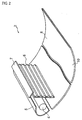
- Fig. 2 is a perspective view of an illuminating unit provided in a display unit.
- This embodiment 1 is a case where the invention is applied to a transmissive-type display unit.
- the display unit 1 comprises a backlight-type illuminating unit 2 and a liquid crystal display panel 3 serving as an object of illumination.
- the liquid crystal display panel 3 is a TN (twisted nematic) type or STN (super-twisted nematic) type liquid crystal display panel.
- the illuminating unit 2 comprises a linear light source 4 such as a fluorescent tube, a condensing cover 5 which surrounds the rear portion of the light source 4 (the left side portion of Fig.
- the prism sheet 6 functions to convert the light from the light source 4 into a parallel light.
- a micro-lens sheet may therefore be used in place of the prism sheet 6.
- the auxiliary reflecting plate 7 shields the light irradiated from the light source 4 directly to the liquid crystal display panel 3, and directs it to the reflecting plate 8 to shield irradiation of the light having a high optical intensity onto the liquid crystal display panel 3, thus serving to improve uniformity of the light onto the liquid crystal display panel 3.
- the reflecting plate 8 is bent in a parabola shape so as to approach the liquid crystal display panel 3 substantially according as the distance from the light source 4 becomes longer.
- the reflecting plate 8 By bending the reflecting plate 8 into a parabola shape as described above, it is possible to irradiate the liquid crystal display panel 3 substantially uniformly.
- light attenuates according as the distance from the light source 4 becomes longer.
- the optical intensity is higher at an end (left side end in Fig. 1) of the liquid crystal display panel 3 on the light source 4 side, whereas the optical intensity is lower at the other end (right side end in Fig.
- the parabolic shape of the reflecting plate 8 suffices to be at least a shape approaching the liquid crystal display panel 3 according as the distance from the light source 4 becomes longer. However, it should preferably be bent so that the incident angle of the incident light from the Light source 4 onto the reflecting surface is substantially constant over the entire reflecting surface 10.
- the reflecting plate 8 has a curved shape satisfying ⁇ 1 ⁇ ⁇ 2 at an arbitrary position on the reflecting surface 10. Since a better balance between the optical intensity and the degree of condensation is available for the illuminating light onto the liquid crystal display panel 3, it is possible to improve uniformity of the illumination.
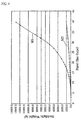
- the illuminating unit of this embodiment As compared with use of a conventional case using a light guide plate, it is possible to achieve a reduced weight and a smaller size of the unit as a whole. This is useful particularly in a display unit using a large-sized display panel.
- the abscissa represents the panel size (shown by diagonal inches), and the ordinate, the backlight weight.
- the line M1 represents the case of a conventional illuminating unit using a light guide plate
- the line M2 shows the case of the illuminating unit of the present invention.
- the weight of the light guide plate is calculated on the basis of the following formula.
- the specific gravity 1.1 of acrylic resin commonly employed is used as that of the light guide plate.
- Light guide plate (light guide plate thickness) x (area of light guide plate) x (specific gravity of light guide plate)
- a larger panel size corresponds to an increased weight in the conventional art.
- an increased size leads to almost no increase in weight.
- the reason is as follows.
- the emitted luminous flux is proportional to a square of the tube diameter, and therefore, also to a square of the distance from the fluorescent tube.
- the panel size is in a linear proportional relationship with the tube diameter.
- a larger tube diameter leads to a larger light guide plate and an increased weight.
- the weight increase depending upon the panel size is slight, because an air layer occupies the most part. This effect becomes apparent for a panel size of at least type 10, and becomes more remarkable for a panel size of over type 15.
- the present inventor prepared a display unit having a backlight as described above to observe display property.
- aluminum was vapor-deposited on an acryl plate by sputtering to manufacture an ordinary thin flat sheet-shaped reflecting plate not subjected to a micro-processing.
- the resultant flat sheet-shaped reflecting plate was bent into a parabolic-shaped reflecting plate 8.
- an illuminating unit was prepared by assembling the reflecting plate 8, a light source 4, a condensing cover 5, a prism sheet 6, and an auxiliary reflecting plate 7.
- a display unit 1 was manufactured by mounting an illuminating unit 2 and a liquid crystal display panel 3.
- the display status of the thus manufactured display unit 1 was observed: luminance non-uniformity was not observed and uniform display was obtained.
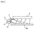
- Fig. 5 is a partial configuration diagram of a display unit of an embodiment 2 of the invention
- Fig. 6 is a side view of a reflecting plate used in the embodiment 2
- Fig. 7 is a plan view of the reflecting plate used in the embodiment 2.
- the embodiment 2 is similar to the embodiment 1, and corresponding component parts are represented by the same reference numerals, omitting a detailed description thereof.
- the micro-projections 15 are omitted to facilitate explanation with the drawing.
- a flat sheet-shaped reflecting plate 8a not bent is used in place of the reflecting plate 8 in the embodiment 1.
- Many micro-projections 15 for adjusting the reflecting angle are formed on the reflecting surface 10 of this reflecting plate 8a.
- Each of the micro-projections 15 has slant surface 16 reflecting an incident light from the light source.
- These micro-projections 15 are arranged so that the inclination angle ⁇ of the slant surface 16 becomes larger according as the distance from the light source 4 becomes longer.
- a reflecting plate 8b on which micro-projections 15 are arranged as shown in Fig. 8 so that the distribution density on the reflecting plate surface becomes gradually larger according as the distance from the light source 4 becomes longer may be used. It is particularly desirable to arrange the micro-projections 15 so as to obtain a quantity of light as represented by a distribution density corresponding to a square of the distance from the light source 4.
- the distribution density of the micro-projections with a distance L1 from the light source 4 is S1
- the distribution density of the micro-projections 15 with a distance L2 from the light source 4 is S2
- it is desirable to arrange the micro-projections 15 so as to satisfy (L1/L2) 2 S1/S2 .
- the micro-projections 15 may be scattered points as shown in Fig.7, or may be linear shape extending in parallel with the light source 4 as shown in Fig. 10.
- the micro-projections 15 are not limited to the rectangular shape as shown in Figs.7 and 10, but may also be triangular or circular in horizontal cross-section.
- the present inventor prepared the aforementioned display unit having a backlight as follows, and observed the display property.
- micro-projections were formed by subjecting an acryl plate to a micro-processing.
- the inclination angle ⁇ of the micro-projections 15 at the position the closest to the light source 4 was set to 0°;
- the inclination angle ⁇ of the micro-projections 15 at the most distant position was set to 30°;
- the inclination angle ⁇ of the micro-projections 15 located therebetween were set so as to achieve an angle distribution giving the quantities of light proportional to a square of the distance from the light source 4.
- the size of a micro-projections 15 was set at 100 ⁇ pitch smaller than a pixel.
- a reflecting plate 8a was prepared by vapor-depositing aluminum by sputtering onto the acryl plate having the micro-projections 15 formed thereon.
- an illuminating unit was manufactured by assembling the reflecting plate 8a, a light source 4, a condensing cover 5, a prism sheet 6, and an auxiliary reflecting plate 7.
- a display unit 1 was manufactured by mounting an illuminating unit 2 and a liquid crystal display panel 3. The display status of the thus manufactured display unit 1 was observed: no luminance non-uniformity was observed and uniform display was obtained. More uniform display was obtained by providing a diffusing plate 9 behind the liquid crystal display panel 3.
- the manufacturing method of the reflecting plate 8a is not limited to the above, but acryl resin may be pressed, or subjected to mold injection. Aluminum may be press-processed, or a photosensitive resin may be photo-etched.
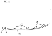
- a reflecting plate 8c shown in Fig. 11 may be used. More specifically, the reflecting plate 8c bent into a parabolic shape and having micro-projections 15 formed thereon may be used. Use of such a reflecting plate 8c permits improvement of uniformity of the illuminating light onto the liquid crystal display panel through reflection at an appropriate angle by the simultaneous use of the curved state of the reflecting plate and the micro-projections 15.
- the present inventor manufactured a display unit 1 in the same manner as in the experiment example 2 except that the reflecting plate 8a prepared in the above-mentioned experiment example 2 was bent into a parabolic shape which was used as a reflecting plate 8c.
- the display property of the thus manufactured display unit 1 was observed: no luminance non-uniformity was observed, and uniform display was obtained. More uniform display was obtained by providing a diffusing plate 9 behind the liquid crystal display panel 3.
- the degree of parallelism was reduced by removing the prism sheet 6: uniformity was somewhat deteriorated and luminance non-uniformity was observed.
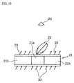
- the diffusing type liquid crystal display panel means a panel conducting display by switching the mode between a transmissive (transparent) state and a diffusion (white muddy) state on the basis of presence or absence of impression of a voltage, including, for example, a liquid crystal display panel using a polymer dispersing type liquid crystal in which liquid crystal drops are dispersed in a polymer, a dynamic type liquid crystal, or a smectic liquid crystal of a heat write diffusion mode.
- the principle of display upon diagonal incidence is as follows.
- the light 20 entering a diffusing plate 21 from the light source becomes a diffused light 22 in a diffused state portion 21a, and becomes a transmitting light 23 without being diffused in a transmissive state portion 21b.
- the observer 24 is in a bright state during diffusion as a result of arrival of the light at the transmissive state portion 21b, and in a dark state during transmission when the light leaves there, thus permitting display of a bright or dark state.
- the light from the light source is originally a diffused light, it keeps the state of diffused light during transmission, and the light reaches in the direction of observation, resulting in a lower contrast between bright and dark states. It is desirable that the light from the light source is a parallel light to some extent.
- any of the reflecting plate 8a, the reflecting plate 8b and the reflecting plate 8c may be used in place of the reflecting plate 8. In this embodiment, however, it is necessary to set an inclination angle ⁇ or a distribution density of the micro-projections 15 from the point of view of irradiating a diagonal light having a high parallelism, in addition to improving uniformity of illumination.
- ultraviolet rays were irradiated from a high-pressure mercury lamp at an intensity of 20 mW/cm 2 (around 360 nm) for 120 seconds onto the panel containing the liquid crystal sealed therein, thereby preparing a liquid crystal display panel 3a of a polymer network structure.
- the display status of the thus manufactured display unit 1 was observed under conditions including a main visual angle of 30° from a perpendicular line of the liquid crystal display panel 3a: there was only a little luminance non-uniformity, and a contrast over 20 was obtained.
- the scattering liquid crystal is not limited to the liquid crystal of the polymer structure, but may be a polymer dispersion liquid crystal, and similar effects was obtained.
- a liquid crystal display unit was manufactured in the same manner as in the Experiment Example 4 by use of a micro-processed reflecting plate 8a as in the Experiment Example 2.
- the shape of the micro-projections 15 was set so that the incident angle of the light to the scattering liquid crystal display panel is at least 30°.
- the main visual angle was set to 30° from the perpendicular line of the liquid crystal display panel 3. Display was tested for the thus manufactured liquid crystal display unit: there was only a little luminance non-uniformity, and a contrast of over 20 was obtained.
- the reflecting plate 8a prepared in the Experiment Example 5 was bent into a parabolic shape (corresponding to the reflecting plate 8c).
- An illuminating unit was manufactured by the same method as in the Experiment Example 5, except for the above. Luminance uniformity was observed for this liquid crystal display unit: a more uniform display was obtained. A contrast of at least 20 was obtained.
- Fig. 14 is a partial configuration diagram of a display unit of the embodiment 5.
- a light source 4 is arranged near the center of a reflecting plate 8d and above the reflecting surface, and is bent into a parabolic shape so as to be closer to the liquid crystal display panel 3 according as the distance from the light source 4 becomes longer.
- micro-projections 15 are not formed on the reflecting surface as in the embodiment 1.
- the area occupied by the reflecting plate is a half that in the case where the reflecting plate is bent, even with the same panel area, thus bringing about the effect of reducing the thickness of the display unit as a whole. This coincides with the case of the embodiments 6 and 7 described later.
- the light shield 17 may be provided to prevent the light from the light source 4 from entering directly into the liquid crystal display panel 3. This permits improvement of the uniformity of illumination.
- liquid crystal panel 3 has been used in the above-mentioned case, the scattering type liquid crystal display panel 3a may be used.
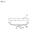
- Fig.15 is a partial configuration diagram of a display unit of the embodiment 6 of the invention.
- the reflecting plate 8e is used.
- the transmission hole 17 of a rectangular shape is formed near the center of the reflecting surface, and the light source 4 is provided in this transmission hole 17.
- the condensing cover 5 is provided behind (bottom side in Fig. 15) the light source 4.
- the micro-projections 15 are not formed on the reflecting surface as in the reflecting plate 8 in the Embodiment 1.
- the reflecting plate 8d is bent into a parabolic shape so that it comes closer to the liquid crystal display panel 3 accordingly as the distance from the light source 4 substantially becomes longer. This configuration permits achievement of a smaller thickness of the display unit as in the Embodiment 5.
- the transmission hole 17 is circular, and point-shaped light sources may be used in place of the linear light source 4. Further, a configuration in which the light source 4 is arranged between two reflecting plates may be used in place of the configuration in which the transmission hole 17 is formed in a single reflecting plate.
- the light shield 17 may be provided directly above the light source 4 in the Embodiment 5.
- liquid crystal display panel 3 While a liquid crystal display panel 3 has been used in the case described above, the scattering type liquid crystal display panel 3a may be used.
- the reflecting plate 8e has been bent into a parabolic shape in the above-mentioned case.
- the present invention is not however limited to this, but the reflecting plate 8e suffices to be bent in a direction, approaching the liquid crystal display panel 3 accordingly as the distance from the light source 4 becomes longer. While the reflecting plate 8e has been used in the above-mentioned case, a reflecting plate having the following configuration may be used in place of the reflecting plate 8e:
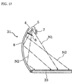
- the reflecting plate 8f shown in Fig. 16 is employed in an Embodiment 7 of the invention.
- This reflecting plate 8f is formed into a bowl shape and has point light sources 4a arranged on the bottom thereof. With the reflecting plate 8f having the above-mentioned configuration, it is possible to achieve a smaller thickness of the display unit as in the aforementioned Embodiments 5 and 6.
- liquid crystal display panel 3 has been used in the case mentioned above, the scattering type liquid crystal display panel 3a may be used.
- the reflecting plate 8f not micro-processed has been used in the above-mentioned case, but a reflecting plate having micro-projections 15 formed on the reflecting surface may be used. Arrangement of the micro-projections 15 in this case suffices to comply with the inclination angle ⁇ or the distribution density as in the above-mentioned reflecting plate 8a or 8b.
- the illuminating unit using the bowl-shaped reflecting plate 8f as described above is applicable not only to an illuminating unit for a liquid crystal display panel, but also to the other illuminating unites, and particularly to a case where the surface to be illuminated of the object of illumination is circular.
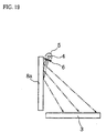
- Fig.17 is a partial configuration diagram of a display unit of an embodiment 8 of the invention
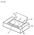
- Fig. 18 is a perspective view illustrating a whole view of the display unit.
- the invention is applied to a reflection type display unit.
- This display unit 30 comprises the front type illuminating unit 31, and the display unit body 32 having a reflection type liquid crystal display panel 33.
- the illuminating unit 31 has basically the same configuration as that of the Backlight-type illuminating unit 2, and the same reference numerals are assigned to corresponding component parts.
- a base end of the reflecting plate 8 is attached to the display unit body 32 so as to permit adjustment of the angle, and the light source 4 is integrally provided at a leading end of the reflecting plate 8.
- the reflecting plate 8 As a result, by setting the reflecting plate 8 to a wide-open state, it is possible to take a long distance between the light source 4 and the reflection type liquid crystal display panel 33. This causes a marked decrease in the difference in the optical path length between the light Nl irradiated from the light source 4 directly onto the reflection type liquid crystal display panel 33 and the light N2 irradiated onto the reflection type liquid crystal display panel 33 via the reflecting plate. Furthermore, the reflecting plate 8 is formed into a parabolic shape. Therefore, making the reflecting plate 8 angle-adjustable and forming it into a parabolic shape make it possible to achieve uniform illumination.
- the reflecting plate 8 can serve as an opening/closing cover, thus permitting prevention of a damage to the display surface of the reflection-type liquid crystal display panel 33.
- any of the reflecting plates 8a, 8b, 8g, and 8c having the aforementioned micro-projections 15 may be used in place of the reflecting plate 8.
- the configuration, in which the light source is arranged near the center of the reflecting plate as in the Embodiments 5, 6, and 7, is applicable to this Embodiment 8 as well.
- the reflection type liquid crystal display panel 33 may be an ordinary TN reflection-type liquid crystal display panel or a scattering-type liquid crystal display panel.
- the diffusing plate 9 may be provided in front of the reflection-type liquid crystal display panel 33. In this configuration, there is available a more uniform display.
- the diffusing plate 9 is not provided. It is because installation of the diffusing plate 9 results in decrease in the contrast.
- the present inventor manufactured a reflection type display unit 30 having the above-mentioned front type illuminating unit as follows, and observed the display property.
- an ordinary TN reflection-type liquid crystal display panel was used as the reflection-type liquid crystal display panel 33, and the reflecting plate 8a was used as the reflecting plate.
- the micro-projections 15 were formed by micro-processing an acryl plate.
- the set angular distribution included an inclination angle ⁇ of the micro-projection 15 at the position the closest to the light source 4 of 0°, an inclination angle ⁇ of the micro-projection 15 at the farthest distant position of 30°, and each inclination angle ⁇ of the micro-projections 15 in the midway to give an amount of light proportional to substantially a square of the distance from the light source 4.
- the size of the micro-projections 15 was set, to 100 ⁇ m pitch, which is a smaller size than the size of a pixel.
- the reflecting plate 8a was manufactured by vapor-depositing aluminum by sputtering on an acryl plate having the micro-projections 15 formed thereon.
- an illuminating unit 31 was manufactured by assembling the reflecting plate 8a, the light source 4, the condensing cover 5, the prism sheet 6, and the auxiliary reflecting plate 7. Then, the display unit 30 shown in Fig. 19 was manufactured by mounting the illuminating unit 31 onto the display unit body 32 having the reflection type liquid crystal display panel 33. To simplify illustration, the micro-projections 15 are omitted in Fig.19.
- the display status of the thus manufactured display unit 30 was observed: no luminance non-uniformity was observed, and a uniform display was obtained.
- a more uniform display was obtained.
- a display unit 30 was manufactured in the same manner as in the Experiment Example 7 except that the reflecting plate 8a manufactured in the Experiment Example 7 was bent into a parabolic shape (corresponding to the reflecting plate 8c). The display status was observed on the display unit 30 of this Experiment Example 8: luminance non-uniformity was not observed, and a uniform display was obtained. By providing the diffusing plate 9 in front of the reflection type liquid crystal display panel 33, a more uniform display was obtained.
- the display unit 30 was manufactured in the same manner as in the Experiment Example 8 except that an ordinary flat sheet-shaped reflecting plate not fine-processed was prepared, and the thus prepared flat sheet-shaped reflecting plate was bent into a parabolic shape (corresponding to the reflecting plate 8).
- the display status was observed on this display unit 30 of this Experiment Example 9: no luminance non-uniformity was observed, and a uniform display was obtained.
- a TFT scattering liquid crystal display panel was used as the reflection type liquid crystal display panel 33, and the reflecting plate 8 was used as the reflecting plate.
- the TFT scattering liquid crystal display panel was manufactured in the same manner as in the above-mentioned Experiment Example 4. Curvature of the reflecting plate 8 was set to a parabolic shape so that the incident angle of the light to the scattering liquid crystal display panel is at least 30° as in the Experiment Example 4. The main visual angle was set to 30° from the perpendicular line of the scattering liquid crystal display panel.
- the display unit 30 was manufactured in the same manner as in the Experiment Example 7 for the other conditions of manufacture. The display status was observed on the display unit 30 of the Experiment Example 10: luminance non-uniformity was not observed, and a contrast of 20 or more was obtained.
- the liquid crystal display unit 30 was manufactured in the same manner as in the Experiment Example 10 by use of the reflecting plate 8a micro-processed in the same manner as in the Experiment Example 7. A shape of micro-projections was set so as to give an incident angle of the light to the scattering liquid crystal display panel of at least 30°. The display status of the display unit 30 of the Experiment Example 11 was observed: only a little luminance non-uniformity was observed, and a contrast of 20 or more was obtained.
- the reflecting plate 8a manufactured in the Experiment Example 11 was bent into a parabolic shape (corresponding to the reflecting plate 8c).
- the liquid crystal display unit 30 was manufactured in the same manner as in the Experiment Example 11 except for the above.
- the display status was observed for the display unit 30 of this Experiment Example 12, including observation of the luminance uniformity of this liquid crystal display unit: there was observed only a little luminance non-uniformity, and contrast of 20 or more was obtained.
- the diffusing plate 9 was inserted in front of the reflection-type liquid crystal display panel (scattering type liquid crystal display panel) 33 in each of the scattering type liquid crystal display units of the above-mentioned Experiment Examples 10, 11, and 12: there was a large decrease in contrast to 2, and the display quality has decreased. By reducing the parallelism of the light from the light source 4 by removing the prism sheet 6, the contrast partially decreased to about 8.
- Fig.20 is a perspective view illustrating a whole exterior configuration of a display unit of the Embodiment 9.
- the light source 4 is provided on the display unit body 32 side.
- the optical path length of the light irradiated from the light source 4 via the reflecting plate 8 onto the liquid crystal display panel 33 is longer than in the Embodiment 5, resulting in a further smaller difference in the optical path length between the irradiated light beams.
- This brings about an advantage of improving the uniformity of illumination.
- provision of the light source 4 on the unit body side facilitates wiring, thus permitting simplification of the configuration of the reflecting plate serving as an opening/closing cover.
- any of the aforementioned reflecting plates 8a, 8b, 8g, and 8c having the micro-projections 15 provided thereon may be used in place of the reflecting plate 8.
- the reflection type liquid crystal display panel 33 may be an ordinary TN reflection-type liquid crystal display panel, or a scattering-type liquid crystal display panel.
- the diffusing plate 9 may be provided in front of the reflection type liquid crystal display panel 33. This gives a more uniform display.
- the diffusing plate 9 is not provided. Installation of the diffusing plate 9 will lead to decrease in the contrast.
- the display unit having a liquid crystal display panel has been described in the above-mentioned Embodiments 1 to 10.
- the present invention is not however limited to this, but also applicable even to a display unit having a display panel built with, for example, an electrophoresis element.
- the illuminating unit of the present invention is applicable not only to a display unit, but also applicable for illuminating a sign, a poster, a photo, or the exhibits in a show window.
- the objects of the invention can sufficiently be achieved. More specifically, they are as follows:
Abstract
Description
- The present invention relates to a backlight-type or Front-type illuminating unit and a display unit having such an illuminating unit.
- In a liquid crystal display unit built with a transmissive-type liquid crystal display panel, it is the conventional practice to adopt an illuminating method known as the backlight type, i.e., an illuminating method of causing panel display by the light irradiated from an illuminating unit provided on the back side of the liquid crystal display panel. Backlight-type illuminating unites are broadly divided into the direct backlight-type and the edge light-backlight type ones.
- The direct backlight-type illuminating unit has a configuration in which a plurality of fluorescent tubes arranged in parallel on the back side of a liquid crystal display panel are used as light sources, and the back side of these fluorescent tubes is further covered with a translucent reflecting plate.
- In the direct backlight-type illuminating unit, however, installation of the fluorescent tubes under the display panel results in a thicker illuminating unit, and hence in a larger overall size of the illuminating unit as a whole.
- The edge-light backlight-type illuminating unit is therefore proposed to solve the above-mentioned problems.
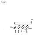
In the edge-light backlight-type illuminating unit, as shown in Fig.22,fluorescent tubes 50 are provided along the edge of alight guide plate 51, and adiffuser 52 is printed on thelight guide plate 51 in response to the distance from thefluorescent tubes 50 so as to achieve uniform illuminating beams to thedisplay panel 53. Further, a reflectingplate 54 is provided under thelight guide plate 51 to improve the utilization rate of light. - Particularly, in the case of a diffusing-type liquid
crystal display panel 55, using a diagonal incident light upon liquid crystal display, it is the usual practice to use a diagonal-shaped visor 56 as shown in Fig.23. - In a conventional liquid-crystal display unit having a configuration in which a reflection-type liquid crystal display panel is provided, an illuminating method known as the front light method, i.e., the illuminating method of causing panel display with the light irradiated from an irradiating unit provided in front of the liquid crystal display panel is commonly adopted. More specifically, as shown in Fig. 24, the
fluorescent lamps 60 are provided along an edge of thelight guide plate 61, and theconcave notches 63 are cut on thelight guide plate 61 in response to the distance from thefluorescent lamps 60 so as to achieve uniformity of the illuminating light beams to the liquidcrystal display panel 62. - However, these conventional configurations have the following problems:
-
- (1) The direct backlight-type illuminating unit has a problem in that installing the fluorescent lamps under the display panel increases the thickness of the illuminating unit, leading to a larger size of the display unit as a whole.
- (2) The edge light backlight-type illuminating unit has a problem of a larger thickness of the display unit as a whole for the necessity of the thickness of the light guide plate. Another defect is that a large-sized screen leads to a larger weight.
- (3) In the case of the diffusion-type liquid crystal display unit, also, it is necessary to manufacture a visor, leading to an increased cost. The thickness is larger as well.
-
- In the front-light-type illuminating unit as well, use of the light guide plate requires an increased thickness of the display unit, and the larger the size of the screen becomes, the more the weight increases.
- The present invention has an object to provide an illuminating unit which permits achievement of a smaller thickness and a reduced weight by eliminating a light guide plate, and to provide a display unit provided with such an illuminating unit.
- To achieve the aforementioned object, the invention of the
claim 1 of the present invention provides an illuminating unit to illuminate an object of illumination, comprising a light source and a reflecting plate, which reflects an incident light from the light source, and directs the reflected light to the object of illumination, wherein the light source is arranged in the proximity of an end of the reflecting plate. - In the aforementioned configuration, an illuminating unit is composed achieving a smaller thickness and a reduced weight by eliminating a light guide plate. The illuminating unit of this invention is applicable to both the front light type and the backlight type. The illuminating unit of this invention is applicable, not only limited, for example, to an illuminating unit of a liquid crystal display unit, but also to the illuminating unites in a wide range including an illuminating unit for the purpose of illuminating the exhibits in a show window.
- The invention of the claim 2 provides an illuminating unit according to the
claim 1, wherein the light source is arranged in the proximity of an end of the reflecting plate. - As described above, the same effects and advantages as those in the invention of the
claim 1 are available also by arranging the light source in the proximity of the reflecting plate. - The invention of the
claim 3 provides an illuminating unit according to theclaim 1, wherein the above said light sources are arranged in the proximity of both ends of the reflecting plate. - As described above, the same effects and advantages as those in the invention of the
claim 1 are available also by arranging the light sources in the proximity of the both ends of the reflecting plate. - The invention of the
claim 4 provides an illuminating unit to illuminate an object of illumination, comprising a light source, and a reflecting plate which reflects an incident light from the light source and to directs the reflected light to the object of illumination, wherein the light source is arranged on a reflecting surface of the reflecting plate. - As described above, the light source may be arranged on the reflecting surface of the reflecting plate.
- The invention of the
claim 5 provides an illuminating unit according to theclaim 4, wherein the light source is arranged in- the proximity of the center of the reflecting surface, and bends in a direction in which the more distant the said reflecting plate is from the light source, the more nearer it approaches the object of illumination. - As compared with a configuration in which the light source is arranged at an end of the reflecting surface, the aforementioned configuration of the illuminating unit in which the reflecting plate bends requires only a slight extent of bending of the reflecting plate even for the same area of the object of illumination, and the reflecting plate suffices to have a thickness of about a half. This permits reduction of the thickness of the illuminating unit in this invention.
- The invention of the
claim 6 provides an illuminating unit of the backlight type, arranged behind an object of illumination, comprising a light source, and a reflecting plate, arranged opposite to the back surfaces of the object of illumination, which reflects an incident light from the light source and directs the reflected light to the object of illumination, wherein the light source is arranged in the proximity of an end of the reflecting plate. - In the above-mentioned configuration, it is possible to illuminate the object of illumination without using a light guide plate, thus achieving a smaller thickness and size reduction of the backlight-type illuminating unit.
- The invention of the
claim 7 provides an illuminating unit according to theclaim 6, wherein the reflecting plate is subjected to a reflecting angle adjusting treatment so that the incident angle of the reflected light entering the object of illumination becomes smaller accordingly as it becomes more distant from the light source so as to uniformly illuminate the object of illumination. - The above-mentioned configuration makes it possible to cause gradual increase in the degree of condensation of the light directed toward the object of illumination accordingly as the distance from the light source becomes longer. As the result, the light has a high light intensity but a small degree of condensation at the portions of the object of illumination near the light source, whereas at the portions distant from the light source, the light has a low light intensity but a large degree of condensation. Consequently, this averages the illuminating light as a whole, thus permitting illumination of the object of illumination substantially to be uniform. It is thus possible to prevent the occurrence of display non-uniformity caused by attenuation of the light to be irradiated onto the object of illumination accordingly as the distance from the light source becomes longer.
- The invention of the
claim 8 provides an illuminating unit according to theclaim 7, wherein the reflecting angle adjusting treatment is to cause the reflecting plate to bend in a direction in which the more distant the said reflecting plate is from the light source, the more nearer it approaches the object of illumination. - In the aforementioned configuration, the reflecting angle on the reflecting plate becomes larger accordingly as the distance from the light source becomes longer. It is therefore become possible to ensure uniform illumination of the object of illumination.
- The invention of the claim 9 provides an illuminating unit according to the
claim 8, wherein the reflecting plate bends in a parabola shape. - By bending the reflecting plate into a parabola shape, as described above, the uniformity of illumination is further improved than that in the invention of the
claim 8. - The invention of the
claim 10 provides an illuminating unit according to theclaim 7, wherein the reflecting angle adjusting treatment is such that a number of the micro-projections each having a slant surface reflecting the incident light from the light source are formed on the reflecting plate, and these micro-projections are arranged so that the inclination angle of the slant surface becomes gradually larger accordingly as it becomes more distant from the light source. - In the aforementioned configuration, the reflecting angle on the reflecting plate becomes larger accordingly as the distance from the light source becomes longer. It is therefore possible to ensure uniform illumination of the object of illumination.
- The invention of the
claim 11 provides an illuminating unit according to theclaim 7, wherein the reflecting angle adjusting treatment is such that a number of the micro-projections each having a slant surface reflecting the incident light from the light source are formed on the reflecting plate, and these micro-projections are arranged so that the distribution density thereof becomes gradually larger accordingly as the distance from the light source becomes longer. - In the aforementioned configuration, the reflecting angle on the reflecting plate becomes larger accordingly as the distance from the light source becomes longer. It is therefore become possible to ensure uniform illumination of the object of illumination.
- The invention of the claim 12 provides an illuminating unit according to the
claim 7, wherein the reflecting angle adjusting treatment is such that the reflecting plate bends in a direction in which the more distant the said reflecting plate is from the light source, the more nearer it approaches the object of illumination, and a number of the micro-projections each having a slant surface reflecting the incident light from the light source are formed on the reflecting plate, and these micro-projections are arranged so that the inclination angle of the slant surface becomes gradually larger accordingly as the distance from the light source becomes longer. - In the above-mentioned configuration, bending of the reflecting plate and a change in the angle of the micro-projections bring about further improvement of the uniformity of illumination.
- The invention of the claim 13 provides an illuminating unit according to the
claim 7, wherein the reflecting angle adjusting treatment is such that the reflecting plate bends in a direction in which the more distant the said reflecting plate is from the light source, the more nearer it approaches the object of illumination, and a number of the micro-projections each having a slant surface reflecting the incident light from the light source are formed on the reflecting plate, and these micro-projections are arranged so that the distribution density thereof becomes gradually larger accordingly as the distance from the light source becomes longer. - In the above-mentioned configuration, bending of the reflecting plate and a change in the angle of the micro-projections bring about further improvement of the uniformity of illumination.
- The invention of the
claim 14 provides an illuminating unit according to theclaim 6, wherein the illuminating unit has optical means which directs the light from the light source substantially in parallel to the reflecting plate. - The aforementioned configuration improves parallelism of the irradiation light onto the reflecting plate, and thereby improves the uniformity of illumination.
- The invention of the
claim 15 provides an illuminating unit according to theclaim 14, wherein a diffusing plate is provided between the reflecting plate and the object of illumination. - In this configuration, the light reflected from the reflecting plate is diffused upon passing through the diffusing plate, thus achieving uniform distribution of the light. As the result, it improves the uniformity of illumination.
- The invention of the
claim 16 provides a display unit built by use of the illuminating unit according to theclaim 6, wherein a transmissive-type liquid crystal display panel is arranged as an object of illumination on the surface side of the reflecting plate of the illuminating unit. - In this configuration, it becomes possible to reduce the thickness and the weight of the illuminating unit, and as the result, it is possible to reduce the thickness and the weight of the display unit as a whole.
- The invention of the
claim 17 provides a display unit built by use of the illuminating unit according to theclaim 6, wherein a transmissive-type liquid crystal display panel is arranged as an object of illumination on the surface side of the reflecting plate of the illuminating unit, and the liquid crystal display panel is a liquid crystal display panel of the diffusion display mode in which the mode is switched over between a transmissive state and a diffusion state on the basis of the presence or absence of impression of a voltage. - The above-mentioned configuration permits the configuration of a display unit of a diffusion display mode that has achieved the reduction of thickness and weight.
- The invention of the claim 18 provides a display unit built by use of the illuminating unit according to the
claim 7, wherein a transmissive-type liquid crystal display panel is arranged as an object of illumination on the surface side of the reflecting plate of the illuminating unit, and the liquid crystal display panel is a liquid crystal display panel of the diffusion display mode in which the mode is switched over between a transmissive state and a diffusion state on the basis of the presence or absence of impression of a voltage; and the reflecting angle adjusting treatment of the reflecting plate is suitable for irradiating a diagonal light of a high parallelism to the liquid crystal display panel, in addition to the uniformity of illumination. - In the aforementioned configuration, a diagonal light having a high parallelism is irradiated onto the liquid crystal display panel. As the result, when the liquid crystal display panel is in a transmissive state (dark state), chances of the light reaching the observer are reduced as far as possible. Consequently, a display unit that gives an improved contrast can be constructed.
- The invention of the claim 19 provides a display unit according to the
claim 17, wherein the display unit has optical means which converts the diffusing light from the light source substantially into a parallel light and directs the same to the reflecting plate. - In the aforementioned configuration, the parallelism of the, irradiated light onto the reflecting plate is improved. It therefore becomes possible to improve the parallelism of the diagonal light.
- The invention of the
claim 20 provides a display unit according to the claim 18, wherein the display unit has optical means which converts the diffusing light from the light source substantially into a parallel light and directs the same to the reflecting plate. - In the aforementioned configuration, the parallelism of the irradiated light onto the reflecting plate is improved. It therefore becomes possible to improve parallelism of the diagonal light.
- The invention of the
claim 21 provides a front-light-type illuminating unit arranged on the front side of an object of illumination, comprising a light source and a reflecting plate reflecting an incident light from the light source and directing the reflected light to an object of illumination; and supporting means that supports a base end of the reflecting plate in a rotatable manner so as to make the angle between the reflecting plate and the object of illumination adjustable, wherein the light source is provided on the leading end side of the reflecting plate. - In the above-mentioned configuration, it is possible to use a longer distance between the light source and the object of illumination by setting the reflecting plate wide open.
- As the result, the difference in optical path length between the reflected light beams irradiated onto the object of illumination via the reflecting plate, and further, the difference in optical path length between the light irradiated onto the object of illumination directly from the light source and the reflected light will largely be reduced as compared with the conventional cases. This improves the uniformity of illumination.
- The invention of the
claim 22 provides a front light type illuminating unit arranged on the front side of an object of illumination, comprising a light source; and a reflecting plate reflecting an incident light to an object of illumination; and supporting means that supports a base end of the reflecting plate in a rotatable manner so as to make the angle between the reflecting plate and the object of illumination adjustable; wherein the said light source is provided on the side of the object of illumination. - In the above-mentioned configuration, the optical path length of the light irradiated onto the object of illumination from the light source via the reflecting plate is increased from that in the configuration in which the light source is provided on the reflecting plate side. This brings about an advantage that the difference in optical path length between the irradiated light beams is reduced, thus leading to an improved the uniformity of illumination.
- The invention of the
claim 23 provide an illuminating unit according to theclaim 21, wherein, when the reflecting plate is at a position opposite to the object of illumination so as to ensure uniform illumination of the object of illumination, the reflecting plate is subjected to a reflecting angle adjusting treatment so that the incident angle of the reflected light entering the object of illumination becomes smaller as it moves toward the base end of the reflecting plate from the leading end. - In the aforementioned configuration, uniformity of the illumination is improved not only through adjustment of the angle of the reflecting plate, but also through a change in the reflecting angle.
- The invention of the
claim 24 provides an illuminating unit according to theclaim 22, wherein, when the reflecting plate is at a position opposite to the object of illumination so as to ensure the uniform illumination of the object of illumination, the reflecting plate is subjected to a reflecting angle adjusting treatment so that the incident angle of the reflected light entering the object of illumination becomes smaller as it moves toward the base end of the reflecting plate from the leading end. - In the aforementioned configuration, uniformity of the illumination is improved not only through adjustment of the angle of the reflecting plate, but also through a change in the reflecting angle.
- The invention of the
claim 25 provides an illuminating unit according to theclaim 23, wherein the reflecting angle adjusting treatment is such that the reflecting plate bends in a direction in which the nearer the said reflecting plate approaches the base end, the nearer it approaches the light source. - In the above-mentioned configuration, the reflecting angle on the reflecting plate becomes larger according as the distance from the light source becomes longer. This makes it possible to uniformly illuminate the object of illumination.
- The invention of the claim 26 provides an illuminating unit according to the
claim 24, wherein the reflecting angle adjusting treatment is such that the reflecting plate bends in a direction in which the nearer the said reflecting plate approaches the base end, the nearer it approaches the light source. - In the above-mentioned configuration, the reflecting angle on the reflecting plate becomes larger accordingly as the distance from the light source becomes longer. This makes it possible to uniformly illuminate the object of illumination.
- The invention of the claim 27 provides an illuminating unit according to the
claim 25, wherein the reflecting plate bends in a parabola shape. - By bending the reflecting plate into a parabola shape as described above, uniformity of the illumination is further improved than that in the invention of the
claim 25. - The invention of the claim 28 provides an illuminating unit according to the claim 26, wherein the reflecting plate bends in a parabola shape.
- By bending the reflecting plate into a parabola shape as described above, uniformity of the illumination is further improved than that in the invention of the claim 26.
- The invention of the claim 29 provides an illuminating unit according to the
claim 23, wherein the reflecting angle adjusting treatment is such that a number of the micro-projections each having a slant surface reflecting the incident light from the light source are formed on the reflecting plate, and these micro-projections are arranged so that the inclination angle of the slant surface becomes gradually larger accordingly as it becomes more distant from the light source. - In the above-mentioned configuration, the reflecting angle on the reflecting plate becomes larger accordingly as the distance from the light source becomes longer. This makes it possible to uniformly illuminate the object of illumination.
- The invention of the
claim 30 provides an illuminating unit according to theclaim 24, wherein the reflecting angle adjusting treatment is such that a number of the micro-projections each having a slant surface reflecting the incident light from the light source are formed on the reflecting plate, and these micro-projections are arranged so that the inclination angle of the slant surface becomes gradually larger accordingly as it becomes more distant from the light source. - In the above-mentioned configuration, the reflecting angle on the reflecting plate becomes larger accordingly as the distance from the light source becomes longer. This makes it possible to uniformly illuminate the object of illumination.
- The invention of the
claim 31 provides an illuminating unit according to theclaim 23, wherein the reflecting angle adjusting treatment is such that a number of the micro-projections each having a slant surface reflecting the incident light from the light source are formed on the reflecting plate, and said micro-projections are arranged so that the distribution density becomes gradually larger accordingly as the distance from the light source becomes longer. - In the above-mentioned configuration, the reflecting angle on the reflecting plate becomes larger according as the distance from the light source becomes longer. This makes it possible to uniformly illuminate the object of illumination.
- The invention of the
claim 32 provides an illuminating unit according to theclaim 24, wherein the reflecting angle adjusting treatment is such that a number of the micro-projections each having a slant surface reflecting the incident light from the light source are formed on the reflecting plate, and these micro-projections are arranged so that the distribution density becomes gradually larger accordingly as the distance from the light source becomes longer. - The invention of the
claim 33 provides an illuminating unit according to theclaim 23, wherein the reflecting angle adjusting treatment is such that the reflecting plate bends in a direction in which the more distant the said reflecting plate is from the light source, the nearer it approaches the object of illumination; and a number of the micro-projections each having a slant surface reflecting the incident light from the light source are formed on the reflecting plate; and these micro-projections are arranged so that the inclination angle of the slant surface becomes gradually larger accordingly as the distance from the light source becomes longer. - In the aforementioned configuration, uniformity of illumination is further improved by bending of the reflecting plate as well as by a change in angle of the micro-projections.
- The invention of the claim 34 provides an illuminating unit according to the
claim 24, wherein the reflecting angle adjusting treatment is such that the reflecting plate bends in a direction in which the more distant the said reflecting plate is from the light source, the nearer it approaches the object of illumination; and a number of the micro-projections each having a slant surface reflecting the incident light from the light source are formed on the reflecting plate; and these micro-projections are arranged so that the inclination angle of the slant surface becomes gradually larger accordingly as the distance from the light source becomes longer. - In the aforementioned configuration, uniformity of illumination is further improved by bending of the reflecting plate as well as by a change in angle of the micro-projections.
- The invention of the
claim 35 provides an illuminating unit according to theclaim 23, wherein the reflecting angle adjusting treatment is such that the reflecting plate bends in a direction in which the more distant the said reflecting plate is from the light source, the nearer it approaches the object of illumination and a number of the micro-projections each having a slant surface reflecting the incident light from the light source are formed on the reflecting plate; and these micro-projections are arranged so that the distribution density thereof becomes gradually larger accordingly as the distance from the light source becomes longer. - In the aforementioned configuration, uniformity of illumination is further improved by bending the reflecting plate as well as by a change in distribution density of the micro-projections.
- The invention of the claim 36 provides an illuminating unit according to the
claim 24, wherein the reflecting angle adjusting treatment is such that the reflecting plate bends in a direction in which the more distant the said reflecting plate is from the light source, the nearer it approaches the object of illumination; and a number of the micro-projections each having a slant surface reflecting the incident light from the light source are formed on the reflecting plate; and these micro-projections are arranged so that the distribution density thereof becomes gradually larger accordingly as the distance from the light source becomes longer. - In the aforementioned configuration, uniformity of illumination is further improved by bending of the reflecting plate as well as by a change in distribution density of the micro-projections.
- The invention of the claim 37 provides an illuminating unit according to the
claim 21, wherein the illuminating unit has optical means which directs the light from the light source substantially in parallel to the reflecting plate. - In the above-mentioned configuration, parallelism of the irradiated light beams onto the reflecting plate is increased, whereby uniformity of the illumination is improved.
- The invention of the claim 38 provides an illuminating unit according to the
claim 22, wherein the illuminating unit has optical means which directs the light from the light source substantially in parallel to the reflecting plate. - In the above-mentioned configuration, parallelism of the irradiated light beams onto the reflecting plate is increased, whereby uniformity of the illumination is improved.
- The invention of the claim 39 provides an illuminating unit according to the claim 37, wherein a diffusing plate is provided in front of the object of illumination.
- In the configuration described above, the light reflected from the reflecting plate is diffused during passage through the diffusing plate, thus achieving uniformity of distribution of the light, resulting in uniformity of the illumination.
- The invention of the
claim 40 provides an illuminating unit according to the claim 38, wherein a diffusing plate is provided in front of the said object of illumination. - In the configuration described above, the light reflected from the reflecting plate is diffused during passage through the diffusing plate, thus achieving uniformity of distribution of the light, resulting in uniformity of the illumination.
- The invention of the claim 41 provides a display unit built by use of an illuminating unit according to the
claim 21, wherein a reflecting type liquid crystal display panel is arranged as an object of illumination. - In the above-mentioned configuration, it is possible to achieve a smaller thickness and a reduced weight of the illuminating unit, thus permitting construction of a display unit achieving a smaller thickness and a reduced weight for the display unit as a whole.
- The invention of the claim 42 provides a display unit built by use of the illuminating unit according to the
claim 22, wherein a reflecting type liquid crystal display panel is arranged as an object of illumination. - In the above-mentioned configuration, it is possible to achieve a smaller thickness and a reduced weight of the illuminating unit, thus permitting construction of a display unit achieving a smaller thickness and a reduced weight for the display unit as a whole.
- The invention of the claim 43 provides a display unit built by use of the illuminating unit according to the
claim 21, wherein a reflecting-type liquid crystal display panel is arranged as an object of illumination on the surface side of the reflecting plate of the illuminating unit; and the liquid crystal display panel is a liquid crystal display panel of the diffusion display mode in which the mode is switched over between a transmissive state and a diffusion state on the basis of the presence or absence of impression of a voltage. - In the configuration described above, a diagonal light having a high parallelism is irradiated onto the liquid crystal display panel. When the liquid crystal display panel is in a transmissive state (dark state), therefore, the light reaching an observer is reduced as far as possible. As a result, there is available a display unit of an improved contrast.
- The invention of the claim 44 provides a display unit using the illuminating unit according to the
claim 22, wherein a reflecting-type liquid crystal display panel is arranged as an object of illumination on the surface side of the reflecting plate of the illuminating unit; and the liquid crystal display panel is a liquid crystal display panel of the diffusion display mode in which the mode is switched over between a transmissive state and a diffusion state on the basis of the presence or absence of impression of a voltage. - In the configuration described above, a diagonal light having a high parallelism is irradiated onto the liquid crystal display panel. When the liquid crystal display panel is in a transmissive state (dark state), therefore, the light reaching an observer is reduced as far as possible. As a result, there is available a display unit of an improved contrast.
-
- Fig. 1 is a simplified configuration diagram of a display unit of an
embodiment 1 of the present invention; - Fig. 2 is a perspective view of an illuminating unit provided in the
display unit of the
embodiment 1 of the invention; - Fig. 3 illustrates a curved state of the reflecting
plate 8; - Fig. 4 is a graph showing the relationship between the panel size and weight for the conventional art and the invention;
- Fig. 5 is a partial configuration diagram of an illuminating unit of an embodiment 2 of the invention;
- Fig. 6 is a side view of a reflecting
plate 8a used in the embodiment 2 of the invention; - Fig. 7 is a plan view of the reflecting
plate 8a used in the embodiment 2 of the invention; - Fig. 8 is a side view of a reflecting
plate 8b used in the embodiment 2 of the invention; - Fig. 9 is a side view of a reflecting
plate 8g used in the embodiment 2 of the invention; - Fig. 10 illustrates a variant of micro-projections 15;
- Fig. 11 is a side view of a reflecting
plate 8c used in anembodiment 3 of the invention; - Fig. 12 is a partial configuration diagram of a display unit of an
embodiment 4 of the invention; - Fig. 13 illustrates the display principle of diffused liquid crystal;
- Fig. 14 is a partial configuration diagram of a display unit of an
embodiment 5 of the invention; - Fig. 15 is a partial configuration diagram of a display unit of an
embodiment 6 of the invention; - Fig. 16 is a partial configuration diagram of a display unit of an
embodiment 7 of the invention; - Fig. 17 is a partial configuration diagram of a display unit of an
embodiment 8 of the invention; - Fig. 18 is a perspective view illustrating an overall exterior
configuration of the display unit of the
embodiment 8 of the invention; - Fig. 19 is a partial configuration diagram of the display unit of an example 7 of the invention;
- Fig. 20 is a perspective view illustrating an overall exterior configuration of a display unit of an embodiment 9 of the invention;
- Fig. 21 is a partial configuration diagram of a display unit of an
embodiment 10 of the invention; - Fig. 22 is a configuration diagram of a conventional example of a backlight-type illuminating unit;
- Fig. 23 is a partial configuration diagram of a conventional example of an illuminating unit for a diffusion type liquid crystal display panel; and
- Fig. 24 is a configuration diagram of a conventional example of a front light illuminating unit.
-
- Embodiments of the present invention will now be described with reference to the drawings.
- Fig. 1 is a simplified configuration diagram of an
embodiment 1 of the present invention; and Fig. 2 is a perspective view of an illuminating unit provided in a display unit. Thisembodiment 1 is a case where the invention is applied to a transmissive-type display unit. Thedisplay unit 1 comprises a backlight-type illuminating unit 2 and a liquidcrystal display panel 3 serving as an object of illumination. The liquidcrystal display panel 3 is a TN (twisted nematic) type or STN (super-twisted nematic) type liquid crystal display panel. The illuminating unit 2 comprises a linearlight source 4 such as a fluorescent tube, a condensingcover 5 which surrounds the rear portion of the light source 4 (the left side portion of Fig. 1), and condenses the light from thelight source 4 onto the front side (right side portion in Fig. 1), aprism sheet 6 arranged in the proximity of thelight source 4, anauxiliary reflecting plate 7 arranged in the proximity of, and above theprism sheet 6, a thin sheet-shaped reflectingplate 8 covering the entire back side (bottom portion in Fig. 1) of the liquidcrystal display panel 3 serving as an object of illumination, and a diffusing plate 9 arranged between the reflectingplate 8 and the liquidcrystal display panel 3. - The
prism sheet 6 functions to convert the light from thelight source 4 into a parallel light. A micro-lens sheet may therefore be used in place of theprism sheet 6. - Further, the
auxiliary reflecting plate 7 shields the light irradiated from thelight source 4 directly to the liquidcrystal display panel 3, and directs it to the reflectingplate 8 to shield irradiation of the light having a high optical intensity onto the liquidcrystal display panel 3, thus serving to improve uniformity of the light onto the liquidcrystal display panel 3. - Further, the reflecting
plate 8 is bent in a parabola shape so as to approach the liquidcrystal display panel 3 substantially according as the distance from thelight source 4 becomes longer. By bending the reflectingplate 8 into a parabola shape as described above, it is possible to irradiate the liquidcrystal display panel 3 substantially uniformly. In general, light attenuates according as the distance from thelight source 4 becomes longer. When light is irradiated onto the liquidcrystal display panel 3 by use of a flat-shaped reflecting plate not bent, therefore, the optical intensity is higher at an end (left side end in Fig. 1) of the liquidcrystal display panel 3 on thelight source 4 side, whereas the optical intensity is lower at the other end (right side end in Fig. 1) of the liquidcrystal display panel 3, thus making it impossible to irradiate the reflecting plate uniformly, and causing occurrence of display non-uniformity. In this respect, it is possible to gradually increase the degree of condensation of the light directed toward the liquidcrystal display panel 3 according as the distance from the light source becomes longer by using a reflectingplate 8 having the above-mentioned shape. As a result, the degree of condensation is small, in spite of a high optical intensity at portions of the liquidcrystal display panel 3 closer to the light source, and in contrast, the degree of condensation become higher, with a lower optical intensity, at portions distant from the light source. Therefore, for illumination of the liquidcrystal display panel 3 as a whole, the illuminating light is averaged, thus permitting substantially uniform illumination of the liquid crystal display panel. It is thus possible to prevent display non-uniformity caused by the attenuation of the quantity of light occurring according as the distance from thelight source 4 of the liquid crystal display panel becomes longer. - The parabolic shape of the reflecting
plate 8 suffices to be at least a shape approaching the liquidcrystal display panel 3 according as the distance from thelight source 4 becomes longer. However, it should preferably be bent so that the incident angle of the incident light from theLight source 4 onto the reflecting surface is substantially constant over the entire reflectingsurface 10. In other words, in a case using incident lights K1 and K2 arbitrarily selected as shown in Fig. 3, if the incident angle of the incident light K1 is 1 and the incident angle of the other incident light K2 is 2, it is desirable that the reflectingplate 8 has a curved shape satisfying 1 ≒ 2 at an arbitrary position on the reflectingsurface 10. Since a better balance between the optical intensity and the degree of condensation is available for the illuminating light onto the liquidcrystal display panel 3, it is possible to improve uniformity of the illumination. - By using the illuminating unit of this embodiment, as compared with use of a conventional case using a light guide plate, it is possible to achieve a reduced weight and a smaller size of the unit as a whole. This is useful particularly in a display unit using a large-sized display panel. The reason will be described with reference to Fig.4. In Fig. 4, the abscissa represents the panel size (shown by diagonal inches), and the ordinate, the backlight weight. In Fig. 4, the line M1 represents the case of a conventional illuminating unit using a light guide plate, and the line M2 shows the case of the illuminating unit of the present invention. The weight of the light guide plate is calculated on the basis of the following formula. The specific gravity 1.1 of acrylic resin commonly employed is used as that of the light guide plate.
- As is clear from Fig.4, a larger panel size corresponds to an increased weight in the conventional art. In the invention, in contrast, an increased size leads to almost no increase in weight. The reason is as follows. In general, in order to keep a constant brightness of liquid crystal display, it is necessary to use thicker fluorescent tubes according as the panel size becomes larger. The emitted luminous flux is proportional to a square of the tube diameter, and therefore, also to a square of the distance from the fluorescent tube. Under the conditions of keeping a constant brightness of the liquid crystal display panel, therefore, the panel size is in a linear proportional relationship with the tube diameter. For this reason, in the conventional art, a larger tube diameter leads to a larger light guide plate and an increased weight. In the present invention using a reflecting plate, in contrast, the weight increase depending upon the panel size is slight, because an air layer occupies the most part. This effect becomes apparent for a panel size of at least
type 10, and becomes more remarkable for a panel size of overtype 15. - The effect of eliminating the light guide plate, as described above, applies also to any of the embodiments 2 to 9 described later.
- The present inventor prepared a display unit having a backlight as described above to observe display property. First, aluminum was vapor-deposited on an acryl plate by sputtering to manufacture an ordinary thin flat sheet-shaped reflecting plate not subjected to a micro-processing. Then, the resultant flat sheet-shaped reflecting plate was bent into a parabolic-shaped reflecting
plate 8. Then, an illuminating unit was prepared by assembling the reflectingplate 8, alight source 4, a condensingcover 5, aprism sheet 6, and anauxiliary reflecting plate 7. Then, adisplay unit 1 was manufactured by mounting an illuminating unit 2 and a liquidcrystal display panel 3. The display status of the thus manufactureddisplay unit 1 was observed: luminance non-uniformity was not observed and uniform display was obtained. By providing a diffusing plate 9 behind the liquidcrystal display panel 3, more uniform display was obtained. - Fig. 5 is a partial configuration diagram of a display unit of an embodiment 2 of the invention; Fig. 6 is a side view of a reflecting plate used in the embodiment 2; and Fig. 7 is a plan view of the reflecting plate used in the embodiment 2. The embodiment 2 is similar to the
embodiment 1, and corresponding component parts are represented by the same reference numerals, omitting a detailed description thereof. In Fig.5, the micro-projections 15 are omitted to facilitate explanation with the drawing. - In the embodiment 2, a flat sheet-shaped reflecting
plate 8a not bent is used in place of the reflectingplate 8 in theembodiment 1. Many micro-projections 15 for adjusting the reflecting angle are formed on the reflectingsurface 10 of this reflectingplate 8a. Each of the micro-projections 15 hasslant surface 16 reflecting an incident light from the light source. Thesemicro-projections 15 are arranged so that the inclination angle þ of theslant surface 16 becomes larger according as the distance from thelight source 4 becomes longer. By providing thesemicro-projections 15, it is possible to gradually increase the degree of condensation of the light irradiated toward the liquidcrystal display panel 3 according as the distance from thelight source 4 becomes longer. Therefore, even with the flat sheet-shaped reflecting plate not bent, it is possible to substantially uniformly illuminate the liquidcrystal display panel 3 as in the parabolic reflectingplate 8 of theaforementioned embodiment 1 by providing the micro-projections. - In place of arranging the micro-projections 15 so that the inclination angle α of the
slant surface 16 becomes larger according as the distance from thelight source 4 becomes longer, a reflectingplate 8b on which micro-projections 15 are arranged as shown in Fig. 8 so that the distribution density on the reflecting plate surface becomes gradually larger according as the distance from thelight source 4 becomes longer may be used. It is particularly desirable to arrange the micro-projections 15 so as to obtain a quantity of light as represented by a distribution density corresponding to a square of the distance from thelight source 4. More specifically, if the distribution density of the micro-projections with a distance L1 from thelight source 4 is S1, and the distribution density of the micro-projections 15 with a distance L2 from thelight source 4 is S2, it is desirable to arrange the micro-projections 15 so as to satisfy - Furthermore, it is also possible to use a reflecting
plate 8 of a configuration based on combination of the above-mentioned inclination angle of the micro-projections 15 and the distribution density of the micro-projections 15 as shown in Fig.9. - The micro-projections 15 may be scattered points as shown in Fig.7, or may be linear shape extending in parallel with the
light source 4 as shown in Fig. 10. The micro-projections 15 are not limited to the rectangular shape as shown in Figs.7 and 10, but may also be triangular or circular in horizontal cross-section. - The present inventor prepared the aforementioned display unit having a backlight as follows, and observed the display property. First, micro-projections were formed by subjecting an acryl plate to a micro-processing. At this point, the inclination angle α of the micro-projections 15 at the position the closest to the
light source 4 was set to 0°; the inclination angle α of the micro-projections 15 at the most distant position was set to 30°; and the inclination angle α of the micro-projections 15 located therebetween were set so as to achieve an angle distribution giving the quantities of light proportional to a square of the distance from thelight source 4. The size of a micro-projections 15 was set at 100 µ pitch smaller than a pixel. Then, a reflectingplate 8a was prepared by vapor-depositing aluminum by sputtering onto the acryl plate having the micro-projections 15 formed thereon. Then, an illuminating unit was manufactured by assembling the reflectingplate 8a, alight source 4, a condensingcover 5, aprism sheet 6, and anauxiliary reflecting plate 7. Then, adisplay unit 1 was manufactured by mounting an illuminating unit 2 and a liquidcrystal display panel 3. The display status of the thus manufactureddisplay unit 1 was observed: no luminance non-uniformity was observed and uniform display was obtained. More uniform display was obtained by providing a diffusing plate 9 behind the liquidcrystal display panel 3. - The manufacturing method of the reflecting
plate 8a is not limited to the above, but acryl resin may be pressed, or subjected to mold injection. Aluminum may be press-processed, or a photosensitive resin may be photo-etched. - A reflecting
plate 8c shown in Fig. 11 may be used. More specifically, the reflectingplate 8c bent into a parabolic shape and havingmicro-projections 15 formed thereon may be used. Use of such a reflectingplate 8c permits improvement of uniformity of the illuminating light onto the liquid crystal display panel through reflection at an appropriate angle by the simultaneous use of the curved state of the reflecting plate and the micro-projections 15. - The following more concrete configurations are conceivable: (1) a curved state of the reflecting plate and the inclination angle α of the micro-projections 15; and (2) a curved state of the reflecting plate and the distribution density of the micro-projections 15.
- The present inventor manufactured a
display unit 1 in the same manner as in the experiment example 2 except that the reflectingplate 8a prepared in the above-mentioned experiment example 2 was bent into a parabolic shape which was used as a reflectingplate 8c. The display property of the thus manufactureddisplay unit 1 was observed: no luminance non-uniformity was observed, and uniform display was obtained. More uniform display was obtained by providing a diffusing plate 9 behind the liquidcrystal display panel 3. - For the
above display unit 1, the degree of parallelism was reduced by removing the prism sheet 6: uniformity was somewhat deteriorated and luminance non-uniformity was observed. - Fig. 12 is a partial configurational view of a display unit of an
embodiment 4 of the invention. Theembodiment 4 is similar to theembodiment 1, and corresponding component parts are represented by the same reference numerals, omitting a detailed description thereof. While the above-mentionedembodiment 1 has covered a TN (twisted nematic) type or STN (super-twisted nematic) type liquidcrystal display panel 3, a scattering type liquidcrystal display panel 3a is used in theembodiment 4. The term the diffusing type liquid crystal display panel means a panel conducting display by switching the mode between a transmissive (transparent) state and a diffusion (white muddy) state on the basis of presence or absence of impression of a voltage, including, for example, a liquid crystal display panel using a polymer dispersing type liquid crystal in which liquid crystal drops are dispersed in a polymer, a dynamic type liquid crystal, or a smectic liquid crystal of a heat write diffusion mode. - The reflecting plate in this embodiment takes the shape of a parabola as in the reflecting plate in the
embodiment 1, with however a different curve shape of the parabola from that in theembodiment 1. In theembodiment 1, more specifically, the curvature of the reflecting plate has been set for the purpose of gradually increasing the degree of condensation of the light directed toward the liquidcrystal display panel 3 accordingly as the distance from the light source becomes longer. The reflecting plate in this embodiment differs from that in theembodiment 1 in that the curvature of the reflecting plate is set so that light beams reflected at any arbitrary position on the reflecting surface are in parallel with each other. In this embodiment, in which a diffusion type liquidcrystal display panel 3a is used, it is necessary to irradiate highly parallel diagonal light onto the liquidcrystal display panel 3a. - The reason will be described in detail. With reference to Fig. 13, the principle of display upon diagonal incidence is as follows. The light 20 entering a diffusing
plate 21 from the light source becomes a diffused light 22 in a diffusedstate portion 21a, and becomes a transmittinglight 23 without being diffused in atransmissive state portion 21b. At this point, theobserver 24 is in a bright state during diffusion as a result of arrival of the light at thetransmissive state portion 21b, and in a dark state during transmission when the light leaves there, thus permitting display of a bright or dark state. As is evident from this principle, when the light from the light source is originally a diffused light, it keeps the state of diffused light during transmission, and the light reaches in the direction of observation, resulting in a lower contrast between bright and dark states. It is desirable that the light from the light source is a parallel light to some extent. - In an ordinary TN (twisted nematic) type liquid crystal, a diffusing plate is provided between the light source and the liquid crystal display panel with a view to achieving uniformity of the light from the backlight. However, in the scattering type display mode, this causes a decrease in contrast, and forms a factor of deteriorating the display quality. For this reason, it is desirable to omit the diffusing plate when using a scattering type liquid crystal display panel.
- As a reflecting plate, any of the reflecting
plate 8a, the reflectingplate 8b and the reflectingplate 8c may be used in place of the reflectingplate 8. In this embodiment, however, it is necessary to set an inclination angle þ or a distribution density of the micro-projections 15 from the point of view of irradiating a diagonal light having a high parallelism, in addition to improving uniformity of illumination. - The present inventor prepared a
display unit 1 having a backlight as described above as follows, and observed the display property. First, a scattering type liquidcrystal display panel 3a was prepared. More specifically, a vacant panel (cell thickness: 4 µm) using a TFT substrate was manufactured by a known manufacturing method. A scattering liquid crystal PN201 (commercial product name) made by Dainihon Ink Co., Ltd. was sealed in the above-mentioned vacant panel by the vacuum injecting method. Then, ultraviolet rays were irradiated from a high-pressure mercury lamp at an intensity of 20 mW/cm2 (around 360 nm) for 120 seconds onto the panel containing the liquid crystal sealed therein, thereby preparing a liquidcrystal display panel 3a of a polymer network structure. - Then, a flat sheet-shaped reflecting plate was fabricated into a parabolic shape (corresponding to the reflecting plate 8) in the same manner as in the Experiment Example 1. The parabolic shape of the reflecting plate at this point was set so that the light incident angle to the scattering liquid
crystal display panel 3a is at least 30þ. Then, an illuminating unit 2 was manufactured by assembling the aforementioned parabola-shaped reflecting plate, alight source 4, a condensingcover 5, aprism sheet 6, and anauxiliary reflecting plate 7. Then, adisplay unit 1 was manufactured by mounting the illuminating unit 2 and the liquidcrystal display panel 3a. The display status of the thus manufactureddisplay unit 1 was observed under conditions including a main visual angle of 30° from a perpendicular line of the liquidcrystal display panel 3a: there was only a little luminance non-uniformity, and a contrast over 20 was obtained. The scattering liquid crystal is not limited to the liquid crystal of the polymer structure, but may be a polymer dispersion liquid crystal, and similar effects was obtained. - A liquid crystal display unit was manufactured in the same manner as in the Experiment Example 4 by use of a
micro-processed reflecting plate 8a as in the Experiment Example 2. The shape of the micro-projections 15 was set so that the incident angle of the light to the scattering liquid crystal display panel is at least 30°. The main visual angle was set to 30° from the perpendicular line of the liquidcrystal display panel 3. Display was tested for the thus manufactured liquid crystal display unit: there was only a little luminance non-uniformity, and a contrast of over 20 was obtained. - The reflecting
plate 8a prepared in the Experiment Example 5 was bent into a parabolic shape (corresponding to the reflectingplate 8c). An illuminating unit was manufactured by the same method as in the Experiment Example 5, except for the above. Luminance uniformity was observed for this liquid crystal display unit: a more uniform display was obtained. A contrast of at least 20 was obtained. - For the scattering type liquid crystal display units of the Experiment Examples 4, 5 and 6, a diffusing plate 9 was inserted between the liquid
crystal display panel 3a and the reflecting plate: this caused a large decrease to 2 of contrast, leading to deterioration of the display quality. Theprism sheet 6 was removed to reduce the degree of parallelism of the light from thelight source 4, and contrast partially decreased to about 8. - Fig. 14 is a partial configuration diagram of a display unit of the
embodiment 5. In thisembodiment 5, alight source 4 is arranged near the center of a reflectingplate 8d and above the reflecting surface, and is bent into a parabolic shape so as to be closer to the liquidcrystal display panel 3 according as the distance from thelight source 4 becomes longer. In this reflectingplate 8d, micro-projections 15 are not formed on the reflecting surface as in theembodiment 1. In such a configuration in which thelight source 4 is arranged near the center of the reflectingplate 8d, the area occupied by the reflecting plate is a half that in the case where the reflecting plate is bent, even with the same panel area, thus bringing about the effect of reducing the thickness of the display unit as a whole. This coincides with the case of theembodiments - When the
light source 4 is arranged near the center, thelight shield 17 may be provided to prevent the light from thelight source 4 from entering directly into the liquidcrystal display panel 3. This permits improvement of the uniformity of illumination. - While the
liquid crystal panel 3 has been used in the above-mentioned case, the scattering type liquidcrystal display panel 3a may be used. - The reflecting
plate 8d has been bent into a parabolic shape in the case described above. The present invention is not however limited to this, but the reflectingplate 8d suffices to be bent in a direction approaching the liquidcrystal display panel 3 according as the distance from thelight source 4 becomes longer. While the reflectingplate 8d has been used in the above-mentioned case, a reflecting plate of any of the following configurations may be used in place of the reflectingplate 8d: - (1) A reflecting plate arranged so that the inclination angle α of the
slant surface 16 gradually becomes larger accordingly as the distance from thelight source 4 becomes longer as in the reflectingplate 8a may be used. - (2) A reflecting plate arranged so that the distribution density of the
micro-projections 15 becomes gradually larger accordingly as the distance
from the
light source 4 becomes longer as in the reflectingplate 8b may be used. - (3) A reflecting plate having a configuration based on a combination of
the inclination angle and the distribution density of the micro-projections 15
as in the reflecting
plate 8g may be used. - (4) A reflecting plate having a configuration based on a combination of
the curvature of the reflecting plate and the inclination angle α of the
micro-projections 15 as in the reflecting
plate 8c, or a configuration based on a combination of the curvature of the reflecting plate and the distribution density of the micro-projections 15 may be used. -
- Fig.15 is a partial configuration diagram of a display unit of the
embodiment 6 of the invention. In thisembodiment 6, the reflectingplate 8e is used. In this reflectingplate 8c, thetransmission hole 17 of a rectangular shape is formed near the center of the reflecting surface, and thelight source 4 is provided in thistransmission hole 17. The condensingcover 5 is provided behind (bottom side in Fig. 15) thelight source 4. The micro-projections 15 are not formed on the reflecting surface as in the reflectingplate 8 in theEmbodiment 1. The reflectingplate 8d is bent into a parabolic shape so that it comes closer to the liquidcrystal display panel 3 accordingly as the distance from thelight source 4 substantially becomes longer. This configuration permits achievement of a smaller thickness of the display unit as in theEmbodiment 5. - The
transmission hole 17 is circular, and point-shaped light sources may be used in place of the linearlight source 4. Further, a configuration in which thelight source 4 is arranged between two reflecting plates may be used in place of the configuration in which thetransmission hole 17 is formed in a single reflecting plate. - The
light shield 17 may be provided directly above thelight source 4 in theEmbodiment 5. - While a liquid
crystal display panel 3 has been used in the case described above, the scattering type liquidcrystal display panel 3a may be used. - The reflecting
plate 8e has been bent into a parabolic shape in the above-mentioned case. The present invention is not however limited to this, but the reflectingplate 8e suffices to be bent in a direction, approaching the liquidcrystal display panel 3 accordingly as the distance from thelight source 4 becomes longer. While the reflectingplate 8e has been used in the above-mentioned case, a reflecting plate having the following configuration may be used in place of the reflectingplate 8e: - (1) A reflecting plate, that is arranged in such a manner that the
inclination angle α of the
slant surface 16 gradually becomes larger accordingly as the distance from the light source becomes longer as in the reflectingplate 8a, may be used. - (2) A reflecting plate, arranged in such a manner that the distribution
density of the micro-provisions 15 becomes gradually larger accordingly as
the distance from the light source becomes longer as in the reflecting
plate 8b, may be used. - (3) A reflecting plate, which has a configuration based on a
combination of the inclination angle and the distribution density of the
micro-projections 15 as in the reflecting
plate 8g, may be used. - (4) A reflecting plate, which has a configuration based on a
combination of the curvature of the reflecting plate and the inclination
angle α of the micro-projections 15 as in the reflecting
plate 8c, or a configuration based on a combination of the curvature of the reflecting plate and the distribution density of the micro-projections 15, may be used. -
- The reflecting
plate 8f shown in Fig. 16 is employed in anEmbodiment 7 of the invention. This reflectingplate 8f is formed into a bowl shape and has pointlight sources 4a arranged on the bottom thereof. With the reflectingplate 8f having the above-mentioned configuration, it is possible to achieve a smaller thickness of the display unit as in the aforementioned Embodiments 5 and 6. - While the liquid
crystal display panel 3 has been used in the case mentioned above, the scattering type liquidcrystal display panel 3a may be used. - The reflecting
plate 8f not micro-processed has been used in the above-mentioned case, but a reflectingplate having micro-projections 15 formed on the reflecting surface may be used. Arrangement of the micro-projections 15 in this case suffices to comply with the inclination angle α or the distribution density as in the above-mentioned reflectingplate - Further, the illuminating unit using the bowl-shaped reflecting
plate 8f as described above is applicable not only to an illuminating unit for a liquid crystal display panel, but also to the other illuminating unites, and particularly to a case where the surface to be illuminated of the object of illumination is circular. - Fig.17 is a partial configuration diagram of a display unit of an
embodiment 8 of the invention; and Fig. 18 is a perspective view illustrating a whole view of the display unit. In thisEmbodiment 8, the invention is applied to a reflection type display unit. Thisdisplay unit 30 comprises the fronttype illuminating unit 31, and thedisplay unit body 32 having a reflection type liquidcrystal display panel 33. The illuminatingunit 31 has basically the same configuration as that of the Backlight-type illuminating unit 2, and the same reference numerals are assigned to corresponding component parts. In this front-type illuminating,unit 31, a base end of the reflectingplate 8 is attached to thedisplay unit body 32 so as to permit adjustment of the angle, and thelight source 4 is integrally provided at a leading end of the reflectingplate 8. As a result, by setting the reflectingplate 8 to a wide-open state, it is possible to take a long distance between thelight source 4 and the reflection type liquidcrystal display panel 33. This causes a marked decrease in the difference in the optical path length between the light Nl irradiated from thelight source 4 directly onto the reflection type liquidcrystal display panel 33 and the light N2 irradiated onto the reflection type liquidcrystal display panel 33 via the reflecting plate. Furthermore, the reflectingplate 8 is formed into a parabolic shape. Therefore, making the reflectingplate 8 angle-adjustable and forming it into a parabolic shape make it possible to achieve uniform illumination. - The reflecting
plate 8 can serve as an opening/closing cover, thus permitting prevention of a damage to the display surface of the reflection-type liquidcrystal display panel 33. - Any of the reflecting
plates aforementioned micro-projections 15 may be used in place of the reflectingplate 8. The configuration, in which the light source is arranged near the center of the reflecting plate as in theEmbodiments Embodiment 8 as well. - The reflection type liquid
crystal display panel 33 may be an ordinary TN reflection-type liquid crystal display panel or a scattering-type liquid crystal display panel. When the reflection-type liquidcrystal display panel 33 is an ordinary TN reflection-type liquid crystal display panel, the diffusing plate 9 may be provided in front of the reflection-type liquidcrystal display panel 33. In this configuration, there is available a more uniform display. When the reflection type liquidcrystal display panel 33 is a scattering-type liquid crystal display panel, the diffusing plate 9 is not provided. It is because installation of the diffusing plate 9 results in decrease in the contrast. - When using a scattering-type liquid crystal display panel, it is necessary to make it possible to irradiate a diagonal light having a high parallelism, as mentioned in the description of the backlight-type illuminating unit as to the curvature of the reflecting plate or the inclination angle and distribution density of the micro-projections.
- The present inventor manufactured a reflection
type display unit 30 having the above-mentioned front type illuminating unit as follows, and observed the display property. In this Experiment Example 7, an ordinary TN reflection-type liquid crystal display panel was used as the reflection-type liquidcrystal display panel 33, and the reflectingplate 8a was used as the reflecting plate. First, the micro-projections 15 were formed by micro-processing an acryl plate. At this time, the set angular distribution included an inclination angle α of the micro-projection 15 at the position the closest to thelight source 4 of 0°, an inclination angle α of the micro-projection 15 at the farthest distant position of 30°, and each inclination angle α of the micro-projections 15 in the midway to give an amount of light proportional to substantially a square of the distance from thelight source 4. The size of the micro-projections 15 was set, to 100 µm pitch, which is a smaller size than the size of a pixel. Then, the reflectingplate 8a was manufactured by vapor-depositing aluminum by sputtering on an acryl plate having the micro-projections 15 formed thereon. Then, an illuminatingunit 31 was manufactured by assembling the reflectingplate 8a, thelight source 4, the condensingcover 5, theprism sheet 6, and theauxiliary reflecting plate 7. Then, thedisplay unit 30 shown in Fig. 19 was manufactured by mounting the illuminatingunit 31 onto thedisplay unit body 32 having the reflection type liquidcrystal display panel 33. To simplify illustration, the micro-projections 15 are omitted in Fig.19. - The display status of the thus manufactured
display unit 30 was observed: no luminance non-uniformity was observed, and a uniform display was obtained. By providing the diffusing plate 9 in front of the reflection-type liquidcrystal display panel 33, a more uniform display was obtained. - A
display unit 30 was manufactured in the same manner as in the Experiment Example 7 except that the reflectingplate 8a manufactured in the Experiment Example 7 was bent into a parabolic shape (corresponding to the reflectingplate 8c). The display status was observed on thedisplay unit 30 of this Experiment Example 8: luminance non-uniformity was not observed, and a uniform display was obtained. By providing the diffusing plate 9 in front of the reflection type liquidcrystal display panel 33, a more uniform display was obtained. - The
display unit 30 was manufactured in the same manner as in the Experiment Example 8 except that an ordinary flat sheet-shaped reflecting plate not fine-processed was prepared, and the thus prepared flat sheet-shaped reflecting plate was bent into a parabolic shape (corresponding to the reflecting plate 8). The display status was observed on thisdisplay unit 30 of this Experiment Example 9: no luminance non-uniformity was observed, and a uniform display was obtained. By providing the diffusing plate 9 in front of the reflection type liquidcrystal display panel 33, a more uniform display was obtained. - In the Experiment Example 10, a TFT scattering liquid crystal display panel was used as the reflection type liquid
crystal display panel 33, and the reflectingplate 8 was used as the reflecting plate. The TFT scattering liquid crystal display panel was manufactured in the same manner as in the above-mentioned Experiment Example 4. Curvature of the reflectingplate 8 was set to a parabolic shape so that the incident angle of the light to the scattering liquid crystal display panel is at least 30° as in the Experiment Example 4. The main visual angle was set to 30° from the perpendicular line of the scattering liquid crystal display panel. Thedisplay unit 30 was manufactured in the same manner as in the Experiment Example 7 for the other conditions of manufacture. The display status was observed on thedisplay unit 30 of the Experiment Example 10: luminance non-uniformity was not observed, and a contrast of 20 or more was obtained. - The liquid
crystal display unit 30 was manufactured in the same manner as in the Experiment Example 10 by use of the reflectingplate 8a micro-processed in the same manner as in the Experiment Example 7. A shape of micro-projections was set so as to give an incident angle of the light to the scattering liquid crystal display panel of at least 30°. The display status of thedisplay unit 30 of the Experiment Example 11 was observed: only a little luminance non-uniformity was observed, and a contrast of 20 or more was obtained. - The reflecting
plate 8a manufactured in the Experiment Example 11 was bent into a parabolic shape (corresponding to the reflectingplate 8c). The liquidcrystal display unit 30 was manufactured in the same manner as in the Experiment Example 11 except for the above. The display status was observed for thedisplay unit 30 of this Experiment Example 12, including observation of the luminance uniformity of this liquid crystal display unit: there was observed only a little luminance non-uniformity, and contrast of 20 or more was obtained. - The diffusing plate 9 was inserted in front of the reflection-type liquid crystal display panel (scattering type liquid crystal display panel) 33 in each of the scattering type liquid crystal display units of the above-mentioned Experiment Examples 10, 11, and 12: there was a large decrease in contrast to 2, and the display quality has decreased. By reducing the parallelism of the light from the
light source 4 by removing theprism sheet 6, the contrast partially decreased to about 8. - Fig.20 is a perspective view illustrating a whole exterior configuration of a display unit of the Embodiment 9. In this Embodiment 9, the
light source 4 is provided on thedisplay unit body 32 side. In this configuration, the optical path length of the light irradiated from thelight source 4 via the reflectingplate 8 onto the liquidcrystal display panel 33 is longer than in theEmbodiment 5, resulting in a further smaller difference in the optical path length between the irradiated light beams. This brings about an advantage of improving the uniformity of illumination. In addition, provision of thelight source 4 on the unit body side facilitates wiring, thus permitting simplification of the configuration of the reflecting plate serving as an opening/closing cover. - Also in the Embodiment 9, as in the above-mentioned
Embodiment 8, any of the aforementioned reflectingplates plate 8. - The reflection type liquid
crystal display panel 33 may be an ordinary TN reflection-type liquid crystal display panel, or a scattering-type liquid crystal display panel. When the reflection-type liquidcrystal display panel 33 is an ordinary TN reflection-type liquid crystal display panel, the diffusing plate 9 may be provided in front of the reflection type liquidcrystal display panel 33. This gives a more uniform display. When the reflection type liquidcrystal display panel 33 is a scattering-type liquid crystal display panel, the diffusing plate 9 is not provided. Installation of the diffusing plate 9 will lead to decrease in the contrast. - Although irradiation has been made with the single
light source 4 from the side of an edge member of the reflecting plate in the above-mentionedEmbodiments 1 to 4, however, in case that the liquidcrystal display panels light sources 4 may be arranged on the both sides of the reflectingplate 8h as shown in Fig. 21. In this case, the portion the most distant from thelight source 4 becomes the center portion of the panel, and the inclination angle α of the micro-projections must match with this. In a configuration in which the light sources are arranged on the both sides of the reflecting plate, it is possible to apply the same to the above-describedEmbodiment 8 as well. - The display unit having a liquid crystal display panel has been described in the above-mentioned
Embodiments 1 to 10. The present invention is not however limited to this, but also applicable even to a display unit having a display panel built with, for example, an electrophoresis element. The illuminating unit of the present invention is applicable not only to a display unit, but also applicable for illuminating a sign, a poster, a photo, or the exhibits in a show window. - The aforementioned concrete embodiments are only the classification of the technical details of the invention, and the invention should not be interpreted in a narrow sense of the words by limiting only to such concrete examples. The invention can be used in various variants within a range not conflicting with the spirit of the invention and the claims thereof.
- According to the configuration of the present invention, as described above, the objects of the invention can sufficiently be achieved. More specifically, they are as follows:
- (1) It is possible to achieve a smaller thickness and a reduced weight of the illuminating unit and the display unit permitting the achievement of a smaller thickness and a reduced weight; and
- (2) In a liquid crystal display unit using a scattering liquid crystal display panel, it is possible to irradiate a diagonal light having a high parallelism onto the scattering liquid crystal display panel, thus permitting reduction of the light reaching the observer in the transmissive state. As a result, there is available a display of a high contrast.
-
Claims (44)
- An illuminating unit illuminating an object of illumination, comprising:a light source and a reflecting plate which reflects an incident light from the light source, and directs the reflected light to the object of illumination, wherein the said light source is arranged in the proximity of an end of the said reflecting plate.
- An illuminating unit according to the claim 1, wherein the said light source is arranged in the proximity of an end of the reflecting plate.
- An illuminating unit according to the claim 1, wherein the said light sources are arranged in the proximity of both ends of the reflecting plate.
- An illuminating unit illuminating an object of illumination, comprising:a light source and a reflecting plate which reflects an incident light from the light source, and directs the reflected light to the object of illumination, wherein the said light source is arranged on a reflecting surface of the reflecting plate.
- An illuminating unit according to the claim 4, wherein the said light source is arranged in the proximity of the center of the reflecting surface, and bends in a direction in which the more distant the said reflecting plate is from the light source, the nearer it approaches the object of illumination.
- An illuminating unit of the backlight type, -arranged behind an object of illumination, comprising:a light source and a reflecting plate, arranged opposite to the both surfaces of the object of illumination, which reflects an incident light from the light source and directs the reflected light to the object of illumination, wherein the light source is arranged in the proximity of an end of the reflecting plate.
- An illuminating unit according to the claim 6, wherein the reflecting plate is subjected to a reflecting angle adjusting treatment so that the incident angle of the reflected light entering the object of illumination becomes smaller accordingly as it becomes more distant from the light source so as to uniformly illuminate the object of illumination.
- An illuminating unit according to the claim 7, wherein the said reflecting angle adjusting treatment is to cause the reflecting plate to bend in a direction approaching the object of illumination according as the reflecting plate becomes more distant from the light source.
- An illuminating unit according to the claim 8, wherein the reflecting plate bends in a parabola shape.
- An illuminating unit according to the claim 7, wherein said reflecting angle adjusting treatment is such that a number of the micro-projections each having a slant surface reflecting the incident light from the light source are formed on the reflecting plate, and these micro-projections are arranged so that the inclination angle of the slant surface becomes gradually larger accordingly as it becomes more distant from the light source.
- An illuminating unit according to the claim 7, wherein the said reflecting angle adjusting treatment is such that a number of the micro-projections each having a slant surface reflecting the incident light from the light source are formed on the reflecting plate, and the said micro-projections are arranged so that the distribution density thereof becomes gradually larger accordingly as the distance from the light source becomes longer.
- An illuminating unit according to the claim 7, wherein the said reflecting angle adjusting treatment is such that the reflecting plate bends in a direction approaching the object of illumination according as the reflecting plate becomes more distant from the light source; a number of the micro-projections each having a slant surface reflecting the incident light from the light source are formed on the reflecting plate; and these micro-projections are arranged so that the inclination angle of the slant surface becomes gradually larger accordingly as the distance from the light source becomes longer.
- An illuminating unit according to the claim 7, wherein the said reflecting angle adjusting treatment is such that the reflecting plate bends in a direction approaching the object of illumination accordingly as the reflecting plate becomes more distant from the light source; a number of the micro-projections each having a slant surface reflecting the incident light from the light source are formed on the reflecting plate; and these micro-projections are arranged so that the distribution density thereof becomes gradually larger accordingly as the distance from the light source becomes longer.
- An illuminating unit according to the claim 6, wherein the said illuminating unit has optical means which directs the light from the light source substantially in parallel to the reflecting plate.
- An illuminating unit according to the claim 14, wherein a diffusing plate is provided between the said reflecting plate and the said object of illumination.
- A display unit built by use of said illuminating unit according to claim 6, wherein:a transmissive liquid crystal display panel is arranged as an object of illumination on the surface side of the reflecting plate of the illuminating unit.
- A display unit built by use of said illuminating unit according to claim 6, wherein:a transmissive liquid crystal display panel is arranged as an object of illumination on the surface side of the reflecting plate of the illuminating unit; and the said liquid crystal display panel is a liquid crystal display panel of the diffusion display mode, in which the mode is switched over between a transmissive state and a diffusion state on the basis of the presence or absence of impression of a voltage.
- A display unit built by use of said illuminating unit according to claim 7, wherein:a transmissive liquid crystal display panel is arranged as an object of illumination on the surface side of the reflecting plate of the illuminating unit; the said liquid crystal display panel is a liquid crystal display panel of the diffusion display mode, in which the mode is switched over between a transmissive state and diffusion state on the basis of the presence or absence of impression of a voltage; and the said reflecting angle adjusting treatment of said reflecting plate is suitable for irradiating a diagonal light of a high parallelism to the liquid crystal display panel, in addition to uniformity of the illumination.
- A display unit according to the claim 17, wherein the said display unit has optical means which converts the diffusing light from the light source substantially into a parallel light, and directs the same to the reflecting plate.
- A display unit according to the claim 18, wherein the said display unit has optical means which converts the diffusing light from the light source substantially into a parallel light, and directs the same to the reflecting plate.
- A front light type illuminating unit arranged on the front side of an object of illumination, comprising:a light source; a reflecting plate that reflects an incident light from the light source and directs the reflected light to an object of illumination; and a supporting means that supports a base end of the reflecting plate in a rotatable manner so as to make the angle between the reflecting plate and the object of illumination adjustable;
wherein the above-described light source is provided on the leading end side of the reflecting plate. - A front light type illuminating unit arranged on the front side of an object of illumination, comprising:a light source; a reflecting plate that reflects an incident light to an object of illumination; and a supporting means that supports a base end of the reflecting plate in a rotatable manner so as to make the angle between the reflecting plate and the object of illumination adjustable;
wherein the above-described light source is provided on the side of the object of illumination. - An illuminating unit according to the claim 21, wherein, when the said reflecting plate is at a position opposite to the object of illumination so as to ensure uniform illumination of the object of illumination, the said reflecting plate is subjected to a reflecting angle adjusting treatment so that the incident angle of the reflected light entering the object of illumination is smaller from the leading end toward the base end of a reflecting plate.
- An illuminating unit according to the claim 22, wherein, when the said reflecting plate is at a position opposite to the object of illumination so as to ensure uniform illumination of the object of illumination, the said reflecting plate is subjected to a reflecting angle adjusting treatment so that the incident angle of the reflected light entering the object of illumination is smaller from the leading end toward the base end of the reflecting plate.
- An illuminating unit according to the claim 23, wherein the said reflecting angle adjusting treatment is such that the reflecting plate bends in a direction in which the nearer the said reflecting plate approaches toward the base end from the leading end, the nearer it approaches the object of illumination
- An illuminating unit according to the claim 24, wherein the said reflecting angle adjusting treatment is such that the reflecting plate bends in a direction in which the nearer the said reflecting plate approaches toward the base end from the leading end, the nearer it approaches the object of illumination
- An illuminating unit according to the claim 25, wherein the reflecting plate bends in a parabola shape.
- An illuminating unit according to the claim 26, wherein the reflecting plate bends in a parabola shape.
- An illuminating unit according to the claim 23, wherein the said reflecting angle adjusting treatment is such that a number of the micro-projections each having a slant surface reflecting the incident light from the light source are formed on the reflecting plate, and these micro-projections are arranged so that the inclination angle of the slant surface becomes gradually larger accordingly as it becomes more distant from the light source.
- An illumination unit according to the claim 24, wherein the said reflecting angle adjusting treatment is such that a number of the micro-projections each having a slant surface reflecting the incident light from the light source are formed on the reflecting plate, and these micro-projections are arranged so that the inclination angle of the slant surface becomes gradually larger accordingly as it becomes more distant from the light source.
- An illuminating unit according to the claim 23, wherein the said reflecting angle adjusting treatment is such that a number of the micro-projections each having a slant surface reflecting the incident light from the light source are formed on the reflecting plate, and these micro-projections are arranged so that the distribution density becomes gradually larger accordingly as the distance from the light source becomes longer.
- An illuminating unit according to the claim 24, wherein the said reflecting angle adjusting treatment is such that a number of the micro-projections each having a slant surface reflecting the incident light from the light source are formed on the reflecting plate, and these micro-projections are arranged so that the distribution density becomes gradually larger accordingly as the distance from the light source becomes longer.
- An illuminating unit according to the claim 23, wherein the said reflecting angle adjusting treatment is such that the reflecting plate bends in a direction in which the more distant the said reflecting plate becomes from the light source, the nearer it approaches the object of illumination; and a number of the micro-projections each having a slant surface reflecting the incident light from the light source are formed on the reflecting plate; and these micro-projections are arranged so that the inclination angle of the slant surface becomes gradually larger accordingly as the distance from the light source becomes longer.
- An illuminating unit according to the claim 24, wherein the said reflecting angle adjusting treatment is such that the reflecting plate bends in a direction in which the more distant the said reflecting plate becomes from the light source, the nearer it approaches the object of illumination; and a number of the micro-projections each having a slant surface reflecting the incident light from the light source are formed on the reflecting plate; and these micro-projections are arranged so that the inclination angle of the slant surface becomes gradually larger accordingly as the distance from the light source becomes longer.
- An illuminating unit according to the claim 23, wherein the said reflecting angle adjusting treatment is such that the reflecting plate bends in a direction in a direction in which the more distant the said reflecting plate becomes from the light source, the nearer it approaches the object of illumination; and a number of the micro-projections each having a slant surface reflecting the incident light from the light source are formed on the reflecting plate; and these micro-projections are arranged so that the distribution density thereof becomes gradually larger accordingly as the distance from the light source becomes longer.
- An illuminating unit according to the claim 24, wherein the said reflecting angle adjusting treatment is such that the reflecting plate bends in a direction in a direction in which the more distant the said reflecting plate becomes from the light source, the nearer it approaches the object of illumination; and a number of the micro-projections each having a slant surface reflecting the incident light from the light source are formed on the reflecting plate; and these micro-projections are arranged so that the distribution density thereof becomes gradually larger accordingly as the distance from the light source become longer.
- An illuminating unit according to the claim 21, wherein the said illuminating unit has optical means which directs the light from the light source substantially in parallel to the reflecting plate.
- An illuminating unit according to the claim 22, wherein the said illuminating unit has optical means which directs the light from the light source substantially in parallel to the reflecting plate.
- An illuminating unit according to the claim 37, wherein a diffusing plate is provided in front of the said object of illumination.
- An illuminating unit according to the claim 38, wherein a diffusing plate is provided in front of the said object of illumination.
- A display unit built by use of the illuminating unit according to the claim 21, wherein:a reflecting type liquid crystal display panel is arranged as an object of illumination.
- A display unit built by use of the illuminating unit according to the claim 22, wherein:a reflecting type liquid crystal display panel is arranged as an object of illumination.
- A display unit built by use of the illuminating unit according to the claim 21, wherein:a reflecting type liquid crystal display panel is arranged as an object of illumination on the surface side of the reflecting plate of the illuminating unit; and the said liquid crystal display panel is a liquid crystal display panel of the diffusion display mode, in which the mode is switched over between a transmissive state and a diffusion state on the basis of the presence or absence of impression of a voltage.
- A display unit built by use of the illuminating unit according to the claim 22, wherein:a reflecting type liquid crystal display panel is arranged as an object of the illumination on the surface side of the reflecting plate of the illuminating unit; and the said liquid crystal display panel is a liquid crystal display panel of the diffusion display mode, in which the mode is switched over between a transmissive state and a diffusion state on the basis of the presence or absence of impression of a voltage.
Applications Claiming Priority (3)
| Application Number | Priority Date | Filing Date | Title |
|---|---|---|---|
| JP5440599 | 1999-03-02 | ||
| JP5440599 | 1999-03-02 | ||
| PCT/JP2000/001159 WO2000052667A1 (en) | 1999-03-02 | 2000-02-28 | Illuminating device and display device provided with the device |
Publications (2)
| Publication Number | Publication Date |
|---|---|
| EP1093105A1 true EP1093105A1 (en) | 2001-04-18 |
| EP1093105A4 EP1093105A4 (en) | 2002-06-12 |
Family
ID=12969801
Family Applications (1)
| Application Number | Title | Priority Date | Filing Date |
|---|---|---|---|
| EP00905396A Withdrawn EP1093105A4 (en) | 1999-03-02 | 2000-02-28 | Illuminating device and display device provided with the device |
Country Status (4)
| Country | Link |
|---|---|
| EP (1) | EP1093105A4 (en) |
| KR (1) | KR20010043176A (en) |
| CN (1) | CN1296604A (en) |
| WO (1) | WO2000052667A1 (en) |
Cited By (9)
| Publication number | Priority date | Publication date | Assignee | Title |
|---|---|---|---|---|
| US7948672B2 (en) | 2008-03-07 | 2011-05-24 | Qualcomm Mems Technologies, Inc. | System and methods for tiling display panels |
| JP2012043772A (en) * | 2010-08-18 | 2012-03-01 | Lg Innotek Co Ltd | Backlight unit and display device using the same |
| US8798425B2 (en) | 2007-12-07 | 2014-08-05 | Qualcomm Mems Technologies, Inc. | Decoupled holographic film and diffuser |
| US8848294B2 (en) | 2010-05-20 | 2014-09-30 | Qualcomm Mems Technologies, Inc. | Method and structure capable of changing color saturation |
| US8872085B2 (en) | 2006-10-06 | 2014-10-28 | Qualcomm Mems Technologies, Inc. | Display device having front illuminator with turning features |
| US8902484B2 (en) | 2010-12-15 | 2014-12-02 | Qualcomm Mems Technologies, Inc. | Holographic brightness enhancement film |
| US9019590B2 (en) | 2004-02-03 | 2015-04-28 | Qualcomm Mems Technologies, Inc. | Spatial light modulator with integrated optical compensation structure |
| US9019183B2 (en) | 2006-10-06 | 2015-04-28 | Qualcomm Mems Technologies, Inc. | Optical loss structure integrated in an illumination apparatus |
| US9025235B2 (en) | 2002-12-25 | 2015-05-05 | Qualcomm Mems Technologies, Inc. | Optical interference type of color display having optical diffusion layer between substrate and electrode |
Families Citing this family (30)
| Publication number | Priority date | Publication date | Assignee | Title |
|---|---|---|---|---|
| KR100455465B1 (en) * | 2002-02-27 | 2004-11-06 | 강한석 | A table with a light emitting booth that emits light of various colors. |
| CN100426010C (en) * | 2002-12-02 | 2008-10-15 | 鸿富锦精密工业(深圳)有限公司 | Light conducting plate and backlight module using the same |
| CN100390638C (en) * | 2003-09-25 | 2008-05-28 | 友达光电股份有限公司 | Light source modular |
| US7508571B2 (en) | 2004-09-27 | 2009-03-24 | Idc, Llc | Optical films for controlling angular characteristics of displays |
| US7807488B2 (en) | 2004-09-27 | 2010-10-05 | Qualcomm Mems Technologies, Inc. | Display element having filter material diffused in a substrate of the display element |
| KR100712107B1 (en) * | 2004-12-09 | 2007-04-27 | 삼성에스디아이 주식회사 | Liquid crystal display device |
| CN100559065C (en) * | 2005-02-07 | 2009-11-11 | 徐佳义 | Transparent illuminating module |
| TWI263098B (en) | 2005-02-16 | 2006-10-01 | Au Optronics Corp | Backlight module |
| CN100386680C (en) * | 2005-02-23 | 2008-05-07 | 友达光电股份有限公司 | Back light module |
| US7845841B2 (en) | 2006-08-28 | 2010-12-07 | Qualcomm Mems Technologies, Inc. | Angle sweeping holographic illuminator |
| US8107155B2 (en) | 2006-10-06 | 2012-01-31 | Qualcomm Mems Technologies, Inc. | System and method for reducing visual artifacts in displays |
| EP2069838A2 (en) | 2006-10-06 | 2009-06-17 | Qualcomm Mems Technologies, Inc. | Illumination device with built-in light coupler |
| US7855827B2 (en) | 2006-10-06 | 2010-12-21 | Qualcomm Mems Technologies, Inc. | Internal optical isolation structure for integrated front or back lighting |
| US7864395B2 (en) | 2006-10-27 | 2011-01-04 | Qualcomm Mems Technologies, Inc. | Light guide including optical scattering elements and a method of manufacture |
| WO2008049377A1 (en) * | 2006-10-27 | 2008-05-02 | Shaohua Ren | Surface light source having a curved reflective surface for illumination |
| US7949213B2 (en) | 2007-12-07 | 2011-05-24 | Qualcomm Mems Technologies, Inc. | Light illumination of displays with front light guide and coupling elements |
| WO2009102731A2 (en) | 2008-02-12 | 2009-08-20 | Qualcomm Mems Technologies, Inc. | Devices and methods for enhancing brightness of displays using angle conversion layers |
| US8654061B2 (en) | 2008-02-12 | 2014-02-18 | Qualcomm Mems Technologies, Inc. | Integrated front light solution |
| KR101268960B1 (en) | 2008-02-22 | 2013-05-29 | 엘지디스플레이 주식회사 | backlight unit |
| US8049951B2 (en) | 2008-04-15 | 2011-11-01 | Qualcomm Mems Technologies, Inc. | Light with bi-directional propagation |
| JP5355261B2 (en) * | 2009-07-07 | 2013-11-27 | 株式会社日立ハイテクノロジーズ | Proximity exposure apparatus, exposure light forming method for proximity exposure apparatus, and display panel substrate manufacturing method |
| CN101858566B (en) * | 2010-04-21 | 2012-02-08 | 刘姝 | Light source reflector used in backlight component and backlight component thereof |
| KR101335791B1 (en) * | 2011-11-16 | 2013-12-02 | 엘지전자 주식회사 | Backlight unit and display apparatus thereof |
| WO2013127249A1 (en) * | 2012-02-28 | 2013-09-06 | 天地融科技股份有限公司 | Electronic device |
| CN103035176B (en) * | 2012-02-28 | 2015-08-05 | 天地融科技股份有限公司 | A kind of electronic equipment |
| KR102404722B1 (en) | 2015-02-02 | 2022-06-02 | 삼성디스플레이 주식회사 | Liquid crystal display device |
| KR102493918B1 (en) | 2016-03-09 | 2023-02-01 | 삼성전자주식회사 | Display apparatus |
| CN105759328B (en) * | 2016-05-17 | 2019-07-30 | 京东方科技集团股份有限公司 | A kind of divergence of beam mechanism, backlight module and display device |
| CN106019709A (en) * | 2016-07-25 | 2016-10-12 | 广州创维平面显示科技有限公司 | Liquid crystal module and liquid crystal display screen |
| CN108873129A (en) * | 2018-06-25 | 2018-11-23 | 深圳市华星光电技术有限公司 | Reflector plate, side entrance back module and liquid crystal display |
Family Cites Families (19)
| Publication number | Priority date | Publication date | Assignee | Title |
|---|---|---|---|---|
| JPS5453998A (en) * | 1977-10-07 | 1979-04-27 | Nichiden Varian Kk | Indicator |
| DE3123369A1 (en) * | 1981-06-12 | 1983-02-03 | Vdo Schindling | Optical waveguide |
| JPS58166379A (en) * | 1982-03-29 | 1983-10-01 | 芝浦メカトロニクス株式会社 | Lighting apparatus for liquid crystal display unit |
| JPS59212876A (en) * | 1983-05-17 | 1984-12-01 | 三菱電機株式会社 | Display |
| JPS62204289A (en) * | 1986-03-04 | 1987-09-08 | 三洋電機株式会社 | Liquid crystal display unit |
| JPS62262023A (en) * | 1986-05-09 | 1987-11-14 | Hitachi Ltd | Liquid crystal display device |
| JPS63228188A (en) * | 1987-03-17 | 1988-09-22 | ソニー株式会社 | Liquid crystal display device |
| JPH0232320A (en) * | 1988-07-21 | 1990-02-02 | Tama Electric Co Ltd | Back lighting device |
| JPH0624857Y2 (en) * | 1988-08-25 | 1994-06-29 | ソニー株式会社 | Backlight device |
| JPH02165373A (en) * | 1988-12-20 | 1990-06-26 | Sharp Corp | Lighting unit for word processor |
| JPH03109590A (en) * | 1989-09-25 | 1991-05-09 | Matsushita Electric Ind Co Ltd | Illuminating device |
| JPH0428623U (en) * | 1990-07-02 | 1992-03-06 | ||
| JPH05281540A (en) * | 1992-03-31 | 1993-10-29 | Toshiba Lighting & Technol Corp | Lighting system and liquid crystal display device |
| US5339179A (en) * | 1992-10-01 | 1994-08-16 | International Business Machines Corp. | Edge-lit transflective non-emissive display with angled interface means on both sides of light conducting panel |
| JPH10115829A (en) * | 1996-10-14 | 1998-05-06 | Seiko Epson Corp | Liquid crystal display device |
| JPH10246886A (en) * | 1997-03-03 | 1998-09-14 | Omron Corp | Device provided with reflection type liquid crystal display panel |
| JPH10268787A (en) * | 1997-03-21 | 1998-10-09 | Sony Corp | Reflection type display device |
| JP3215346B2 (en) * | 1997-03-28 | 2001-10-02 | シャープ株式会社 | Forward illumination device and reflection type liquid crystal display device having the same |
| JPH11212084A (en) * | 1998-01-23 | 1999-08-06 | Sharp Corp | Electronic equipment |
-
2000
- 2000-02-28 CN CN00800250A patent/CN1296604A/en active Pending
- 2000-02-28 EP EP00905396A patent/EP1093105A4/en not_active Withdrawn
- 2000-02-28 WO PCT/JP2000/001159 patent/WO2000052667A1/en not_active Application Discontinuation
- 2000-02-28 KR KR1020007012097A patent/KR20010043176A/en not_active IP Right Cessation
Non-Patent Citations (2)
| Title |
|---|
| No further relevant documents disclosed * |
| See also references of WO0052667A1 * |
Cited By (9)
| Publication number | Priority date | Publication date | Assignee | Title |
|---|---|---|---|---|
| US9025235B2 (en) | 2002-12-25 | 2015-05-05 | Qualcomm Mems Technologies, Inc. | Optical interference type of color display having optical diffusion layer between substrate and electrode |
| US9019590B2 (en) | 2004-02-03 | 2015-04-28 | Qualcomm Mems Technologies, Inc. | Spatial light modulator with integrated optical compensation structure |
| US8872085B2 (en) | 2006-10-06 | 2014-10-28 | Qualcomm Mems Technologies, Inc. | Display device having front illuminator with turning features |
| US9019183B2 (en) | 2006-10-06 | 2015-04-28 | Qualcomm Mems Technologies, Inc. | Optical loss structure integrated in an illumination apparatus |
| US8798425B2 (en) | 2007-12-07 | 2014-08-05 | Qualcomm Mems Technologies, Inc. | Decoupled holographic film and diffuser |
| US7948672B2 (en) | 2008-03-07 | 2011-05-24 | Qualcomm Mems Technologies, Inc. | System and methods for tiling display panels |
| US8848294B2 (en) | 2010-05-20 | 2014-09-30 | Qualcomm Mems Technologies, Inc. | Method and structure capable of changing color saturation |
| JP2012043772A (en) * | 2010-08-18 | 2012-03-01 | Lg Innotek Co Ltd | Backlight unit and display device using the same |
| US8902484B2 (en) | 2010-12-15 | 2014-12-02 | Qualcomm Mems Technologies, Inc. | Holographic brightness enhancement film |
Also Published As
| Publication number | Publication date |
|---|---|
| CN1296604A (en) | 2001-05-23 |
| KR20010043176A (en) | 2001-05-25 |
| WO2000052667A1 (en) | 2000-09-08 |
| EP1093105A4 (en) | 2002-06-12 |
Similar Documents
| Publication | Publication Date | Title |
|---|---|---|
| EP1093105A1 (en) | Illuminating device and display device provided with the device | |
| JP4042829B2 (en) | Liquid crystal display | |
| CN100564994C (en) | Surface light source apparatus | |
| KR101332317B1 (en) | Backlight unit and liquid crystal display using the same | |
| JP2000030515A (en) | Planar lighting system | |
| KR20070021378A (en) | Back light assembly and liquid crystal display having the same | |
| US7854526B2 (en) | Lamp holder | |
| US20060007101A1 (en) | Liquid crystal display | |
| KR20070040957A (en) | Prism sheet including reflection particles and backlight unit including the same | |
| JP2000315056A (en) | Illuminator and display device equipped with that illuminator | |
| KR20060127609A (en) | A prism sheet employed in backlight unit | |
| JP3098297U (en) | Direct backlight unit | |
| US7494242B2 (en) | Backlight assembly including a diffuser plate having indented portions and a reflective plate having lamp insertion portions | |
| KR100834125B1 (en) | The back light unit | |
| US20040109314A1 (en) | Backlight module | |
| JPH08166586A (en) | Display device | |
| JP2004198725A (en) | Liquid crystal display, direct back light, and diffusing plate | |
| JP4147824B2 (en) | Liquid crystal display | |
| KR101296456B1 (en) | Back light Unit and Liquid Crystal Display using the same | |
| JP4394497B2 (en) | Lighting device | |
| US20090096955A1 (en) | Liquid Crystal Display Appliance and Lighting System | |
| KR101104259B1 (en) | A prism sheet employed in backlight unit | |
| KR20080040975A (en) | Back-light assembly and liquid crystal display having the same | |
| KR20070029392A (en) | Prism sheet having concave and convex portions and backlight unit including the same | |
| KR100877411B1 (en) | A brightness enhancing sheet, a backlight unit, an lcd device including the same, and a method of manufacturing the same |
Legal Events
| Date | Code | Title | Description |
|---|---|---|---|
| PUAI | Public reference made under article 153(3) epc to a published international application that has entered the european phase |
Free format text: ORIGINAL CODE: 0009012 |
|
| 17P | Request for examination filed |
Effective date: 20001204 |
|
| AK | Designated contracting states |
Kind code of ref document: A1 Designated state(s): DE NL |
|
| A4 | Supplementary search report drawn up and despatched |
Effective date: 20020426 |
|
| AK | Designated contracting states |
Kind code of ref document: A4 Designated state(s): DE NL |
|
| RIC1 | Information provided on ipc code assigned before grant |
Free format text: 7F 21V 8/00 A, 7G 02F 1/13357B |
|
| STAA | Information on the status of an ep patent application or granted ep patent |
Free format text: STATUS: THE APPLICATION IS DEEMED TO BE WITHDRAWN |
|
| 18D | Application deemed to be withdrawn |
Effective date: 20030902 |
|
| RBV | Designated contracting states (corrected) |
Designated state(s): DE |