EP1092883A2 - Self-aligning roller bearing - Google Patents
Self-aligning roller bearing Download PDFInfo
- Publication number
- EP1092883A2 EP1092883A2 EP00101418A EP00101418A EP1092883A2 EP 1092883 A2 EP1092883 A2 EP 1092883A2 EP 00101418 A EP00101418 A EP 00101418A EP 00101418 A EP00101418 A EP 00101418A EP 1092883 A2 EP1092883 A2 EP 1092883A2
- Authority
- EP
- European Patent Office
- Prior art keywords
- rollers
- self
- roller bearing
- aligning roller
- rows
- Prior art date
- Legal status (The legal status is an assumption and is not a legal conclusion. Google has not performed a legal analysis and makes no representation as to the accuracy of the status listed.)
- Withdrawn
Links
Images


Classifications
-
- F—MECHANICAL ENGINEERING; LIGHTING; HEATING; WEAPONS; BLASTING
- F16—ENGINEERING ELEMENTS AND UNITS; GENERAL MEASURES FOR PRODUCING AND MAINTAINING EFFECTIVE FUNCTIONING OF MACHINES OR INSTALLATIONS; THERMAL INSULATION IN GENERAL
- F16C—SHAFTS; FLEXIBLE SHAFTS; ELEMENTS OR CRANKSHAFT MECHANISMS; ROTARY BODIES OTHER THAN GEARING ELEMENTS; BEARINGS
- F16C33/00—Parts of bearings; Special methods for making bearings or parts thereof
- F16C33/30—Parts of ball or roller bearings
- F16C33/46—Cages for rollers or needles
- F16C33/48—Cages for rollers or needles for multiple rows of rollers or needles
-
- F—MECHANICAL ENGINEERING; LIGHTING; HEATING; WEAPONS; BLASTING
- F16—ENGINEERING ELEMENTS AND UNITS; GENERAL MEASURES FOR PRODUCING AND MAINTAINING EFFECTIVE FUNCTIONING OF MACHINES OR INSTALLATIONS; THERMAL INSULATION IN GENERAL
- F16C—SHAFTS; FLEXIBLE SHAFTS; ELEMENTS OR CRANKSHAFT MECHANISMS; ROTARY BODIES OTHER THAN GEARING ELEMENTS; BEARINGS
- F16C23/00—Bearings for exclusively rotary movement adjustable for aligning or positioning
- F16C23/06—Ball or roller bearings
- F16C23/08—Ball or roller bearings self-adjusting
- F16C23/082—Ball or roller bearings self-adjusting by means of at least one substantially spherical surface
- F16C23/086—Ball or roller bearings self-adjusting by means of at least one substantially spherical surface forming a track for rolling elements
-
- F—MECHANICAL ENGINEERING; LIGHTING; HEATING; WEAPONS; BLASTING
- F16—ENGINEERING ELEMENTS AND UNITS; GENERAL MEASURES FOR PRODUCING AND MAINTAINING EFFECTIVE FUNCTIONING OF MACHINES OR INSTALLATIONS; THERMAL INSULATION IN GENERAL
- F16C—SHAFTS; FLEXIBLE SHAFTS; ELEMENTS OR CRANKSHAFT MECHANISMS; ROTARY BODIES OTHER THAN GEARING ELEMENTS; BEARINGS
- F16C33/00—Parts of bearings; Special methods for making bearings or parts thereof
- F16C33/30—Parts of ball or roller bearings
- F16C33/34—Rollers; Needles
- F16C33/36—Rollers; Needles with bearing-surfaces other than cylindrical, e.g. tapered; with grooves in the bearing surfaces
-
- F—MECHANICAL ENGINEERING; LIGHTING; HEATING; WEAPONS; BLASTING
- F16—ENGINEERING ELEMENTS AND UNITS; GENERAL MEASURES FOR PRODUCING AND MAINTAINING EFFECTIVE FUNCTIONING OF MACHINES OR INSTALLATIONS; THERMAL INSULATION IN GENERAL
- F16C—SHAFTS; FLEXIBLE SHAFTS; ELEMENTS OR CRANKSHAFT MECHANISMS; ROTARY BODIES OTHER THAN GEARING ELEMENTS; BEARINGS
- F16C33/00—Parts of bearings; Special methods for making bearings or parts thereof
- F16C33/30—Parts of ball or roller bearings
- F16C33/46—Cages for rollers or needles
- F16C33/49—Cages for rollers or needles comb-shaped
- F16C33/494—Massive or moulded comb cages
- F16C33/495—Massive or moulded comb cages formed as one piece cages, i.e. monoblock comb cages
- F16C33/497—Massive or moulded comb cages formed as one piece cages, i.e. monoblock comb cages made from metal, e.g. cast or machined comb cages
-
- F—MECHANICAL ENGINEERING; LIGHTING; HEATING; WEAPONS; BLASTING
- F16—ENGINEERING ELEMENTS AND UNITS; GENERAL MEASURES FOR PRODUCING AND MAINTAINING EFFECTIVE FUNCTIONING OF MACHINES OR INSTALLATIONS; THERMAL INSULATION IN GENERAL
- F16C—SHAFTS; FLEXIBLE SHAFTS; ELEMENTS OR CRANKSHAFT MECHANISMS; ROTARY BODIES OTHER THAN GEARING ELEMENTS; BEARINGS
- F16C19/00—Bearings with rolling contact, for exclusively rotary movement
- F16C19/22—Bearings with rolling contact, for exclusively rotary movement with bearing rollers essentially of the same size in one or more circular rows, e.g. needle bearings
- F16C19/34—Bearings with rolling contact, for exclusively rotary movement with bearing rollers essentially of the same size in one or more circular rows, e.g. needle bearings for both radial and axial load
- F16C19/38—Bearings with rolling contact, for exclusively rotary movement with bearing rollers essentially of the same size in one or more circular rows, e.g. needle bearings for both radial and axial load with two or more rows of rollers
Definitions
- the present invention relates to a self-aligning roller bearing having a self-aligning function.
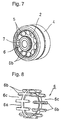
- a self-aligning roller bearing is provided with an inner race 2 having a single spherical orbit 1 and an outer race 4 having two convex orbits 3.
- a plurality of hourglass shaped concave rollers 5 are disposed in two rows between the above-described spherical orbit 1 and the convex orbits 3.
- the concave rollers 5 (hereinafter simply referred to as rollers) on each row are arranged equidistantly in the circumferential direction by a retainer 6.
- the center of the spherical orbit 1 of the inner race 2 is identified with a bearing center O. Even if the axes of the inner race 2 and the outer race 4 are inclined, it is possible to obtain a stable rotation.
- a sleeve 7 is fitted in and fixed to the inner race 2 and at the same time a seal means composed of a seal 8 and a shield 9 is interposed between the sleeve 7 and the outer race 4 to form a unity assembly.
- a seal means composed of a seal 8 and a shield 9 is interposed between the sleeve 7 and the outer race 4 to form a unity assembly.
- a self-aligning roller bearing in which a spherical orbit and two rows of concave orbits are provided on the outer race and the inner race, respectively, and barrel-shaped spherical rollers are arranged between the confronting orbits (for example, see Japanese Patent Application Laid-Open No. Hei 9-317760 and Japanese Patent Application Laid-Open No. Hei 8-128450) has the same function as that of the bearing shown above.
- the above-described retainer 6 is shaped such that a plurality of pillar portions 6b thereof extend like teeth of comb from both sides of a ring portion 6a in both directions of the axial direction so that pockets 6c between the adjacent pillar portions 6b may be used as retainer portions of the rollers 5. Then, conventionally, such a retainer 6 is cast into one piece and thereafter is finished by machining. However, it is necessary to use expensive molds for casting because its shape is complicated, and it is likely that the casting default occurs. Thus, there is a problem that the retainer per se is expensive, which inevitably leads the cost of the overall bearing to be high.
- the retainer is divided into the right and left parts and the halves are punched out of a steel plate (for example, see the above-described Japanese Patent Application Laid-Open No. Hei 8-128450).
- the number of the components is increased and at the same time the number of the assembling steps is increased so that the cost could not be reduced so much.
- an object of the present invention is to provide a self-aligning roller bearing which makes it possible to omit an expensive retainer to thereby largely contribute to reduction of the cost.
- a self-aligning roller bearing in which two rows of rollers are arranged between orbits of an inner race and an outer race, is characterized in that rollers of each row are arranged compactly.
- the retainer for arranging the rollers equidistantly in the circumferential direction may be dispensed with.
- the cost reduction may be attained.
- a ring may be interposed between the rows of rollers or an annular projection for separating the two rows of rollers may be provided on at least either of the outer or inner races having two rows of orbits.
- the ring or the annular projection functions as a separation means for separating the rollers into two rows, the assembling work of the rollers is facilitated.
- the present invention may be applied to any type of self-aligning mechanisms.
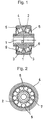
- Figs. 1 to 3 show a self-aligning roller bearing if in accordance with a first embodiment of the present invention.
- the overall structure of the bearing is the same as that of a concave roller type self-aligning roller bearing shown in Figs. 6 and 7 except for a point that the retainer 6 is dispensed with, the same reference numerals are used to indicate the like parts and the duplicated explanation will be omitted.
- two rows of rollers (concave rollers) 5 disposed between a spherical orbit 1 of an inner race 2 and two convex orbits 3 of an outer race 4 are compactly arranged in contact with each other, whereby a retainer 6 (shown in Figs. 6 to 8) which has been conventionally required to arrange the rollers 5 equidistantly in the circumferential direction may be omitted.
- the expensive retainer 6 which has been conventionally required may be omitted because the rollers 5 are compactly arranged. Corresponding to this omission, the cost reduction may be achieved.
- the rollers 5 are arranged compactly, the number of the rollers 5 in each row is increased in comparison with the conventional case. Corresponding to this increment, the load bearing performance is enhanced in comparison with the conventional case. Incidentally, in the case where the same primary dimension is taken, the number of the rollers 5 in the embodiment of the present invention is thirteen, whereas the number of the rollers 5 of the conventional bearing (Figs. 6 and 7) having the retainer 6 is eleven.
- the durable load limit SLR according to the embodiment is increased by about 18% (13/11) relative to the durable load limit SLR of the conventional bearing and is superior in load bearing performance.
- the bearing would have a disadvantage in rotational torque because the rollers 5 are rotated in contact with each other in the same direction.
- this does not cause any serious problem and in the case where the bearing is used as an intermediate or low speed type one, there is no problem at all.
- Fig. 4 shows a self-aligning roller bearing in accordance with a second embodiment of the present invention.
- the second embodiment of the invention is characterized in that a ring 10 is interposed between the rollers 5 arranged in two rows.
- the ring 10 is in the form of a triangular shape corresponding to an opening angle of the right and left rollers and its inner diameter is set to be slightly larger than an outer diameter of the inner race 2.
- Such a ring 10 is arranged between the inner race 2 and the outer race 4 in advance so that the ring 10 functions as a separation means for separating the rollers 5 into two rows to facilitate the assembling work of the rollers 5.
- Fig. 5 shows a self-aligning roller bearing in accordance with a third embodiment of the present invention.
- the third embodiment of the invention is characterized in that an annular projection 11 for separating the two rows of rollers 5 is provided in the middle, in the axial direction, of the inner circumferential surface of the outer race 4 instead of the ring 10 according to the second embodiment.
- the annular projection 11 functions as the separation means for separating the rollers 5 into two rows to ensure the like effect.
- the rollers 5 since the annular projection 11 is provided integrally with the outer race 4, the rollers 5 may be directly assembled, which is advantageous in cost in addition to the reduction of the number of the components.
- the self-aligning roller bearing according to the present invention since the expensive retainer may be dispensed with, it is possible to reduce the overall cost. Also, corresponding to the omission of the retainer, it is possible to increase the number of the rollers to thereby enhance the load bearing performance.
Landscapes
- Engineering & Computer Science (AREA)
- General Engineering & Computer Science (AREA)
- Mechanical Engineering (AREA)
- Support Of The Bearing (AREA)
- Rolling Contact Bearings (AREA)
Abstract
Description
Claims (3)
- A self-aligning roller bearing in which two rows of rollers are arranged between orbits of an inner race and an outer race, comprising an improvement in which the rollers in each row are arranged compactly.
- The self-aligning roller bearing according to claim 1, wherein a ring is interposed between the rows of rollers.
- The self-aligning roller bearing according to claim 1, wherein an annular projection for separating the two rows of rollers is provided on at least either of the outer or inner races having two rows of orbits.
Applications Claiming Priority (2)
| Application Number | Priority Date | Filing Date | Title |
|---|---|---|---|
| JP27424999A JP2001099146A (en) | 1999-09-28 | 1999-09-28 | Self-aligning roller bearing |
| JP27424999 | 1999-09-28 |
Publications (2)
| Publication Number | Publication Date |
|---|---|
| EP1092883A2 true EP1092883A2 (en) | 2001-04-18 |
| EP1092883A3 EP1092883A3 (en) | 2002-12-18 |
Family
ID=17539084
Family Applications (1)
| Application Number | Title | Priority Date | Filing Date |
|---|---|---|---|
| EP00101418A Withdrawn EP1092883A3 (en) | 1999-09-28 | 2000-01-25 | Self-aligning roller bearing |
Country Status (2)
| Country | Link |
|---|---|
| EP (1) | EP1092883A3 (en) |
| JP (1) | JP2001099146A (en) |
Cited By (3)
| Publication number | Priority date | Publication date | Assignee | Title |
|---|---|---|---|---|
| EP2525112A1 (en) * | 2011-05-17 | 2012-11-21 | Schaeffler Technologies AG & Co. KG | Axial floating bearing |
| US9227720B2 (en) | 2013-03-01 | 2016-01-05 | Roller Bearing Company Of America, Inc. | Composite annular seal assembly for bearings in aircraft |
| US10082179B2 (en) | 2014-12-16 | 2018-09-25 | Roller Bearing Company Of America, Inc. | Seal for self aligning roller bearing |
Family Cites Families (5)
| Publication number | Priority date | Publication date | Assignee | Title |
|---|---|---|---|---|
| US1548821A (en) * | 1920-09-23 | 1925-08-11 | Wilhelm B Bronander | Roller bearing |
| US1914548A (en) * | 1931-07-29 | 1933-06-20 | Wingquist Sven Gustaf | Double-row roller bearing |
| US1967650A (en) * | 1932-11-04 | 1934-07-24 | Skf Svenska Kullagerfab Ab | Roller bearing |
| JPS61175318A (en) * | 1985-01-24 | 1986-08-07 | レツクスノルド インコーポレーテツド | Selectively cured bearing which can be caulked |
| US5441351A (en) * | 1993-10-26 | 1995-08-15 | Rexnord Corporation | Full complement self-aligning roller bearing |
-
1999
- 1999-09-28 JP JP27424999A patent/JP2001099146A/en active Pending
-
2000
- 2000-01-25 EP EP00101418A patent/EP1092883A3/en not_active Withdrawn
Cited By (3)
| Publication number | Priority date | Publication date | Assignee | Title |
|---|---|---|---|---|
| EP2525112A1 (en) * | 2011-05-17 | 2012-11-21 | Schaeffler Technologies AG & Co. KG | Axial floating bearing |
| US9227720B2 (en) | 2013-03-01 | 2016-01-05 | Roller Bearing Company Of America, Inc. | Composite annular seal assembly for bearings in aircraft |
| US10082179B2 (en) | 2014-12-16 | 2018-09-25 | Roller Bearing Company Of America, Inc. | Seal for self aligning roller bearing |
Also Published As
| Publication number | Publication date |
|---|---|
| EP1092883A3 (en) | 2002-12-18 |
| JP2001099146A (en) | 2001-04-10 |
Similar Documents
| Publication | Publication Date | Title |
|---|---|---|
| US4906112A (en) | Multirow ball or roller bearing or combined ball/roller bearing | |
| US5540575A (en) | High speed rotating apparatus having face-to-face angular contact ball bearings | |
| US6367980B1 (en) | Ultra thin type rolling bearing and cage therefor | |
| JPH1144322A (en) | Hub unit bearing and manufacture therefor | |
| US4568205A (en) | Race wire bearing | |
| EP1069328A1 (en) | Retainer for rolling bearing | |
| US6616339B2 (en) | Roller bearing | |
| JP2004245251A (en) | Spherical roller bearing | |
| US4138169A (en) | Two row rolling bearing assembly having single piece inner ring and two piece outer ring | |
| JP2008232310A (en) | Roller bearing | |
| JP2689546B2 (en) | Rotation support | |
| JP3757309B2 (en) | Pinion shaft support bearing unit | |
| JP3025594B2 (en) | Four-row tapered roller bearing | |
| JPS639720A (en) | Rolling bearing clearance compensation device | |
| JP2001099146A (en) | Self-aligning roller bearing | |
| JPH0336735Y2 (en) | ||
| JP2004100866A (en) | Retainer for self-aligning roller bearing | |
| JPS58166126A (en) | Linear ball bearing | |
| JP2000213545A (en) | Roller bearing cage | |
| JP3633245B2 (en) | Double row rolling bearing device | |
| JP3928922B2 (en) | Ball bearing | |
| JPH04157208A (en) | Needle type roller bearing | |
| JP2543403Y2 (en) | Bearing for large end of connecting rod of engine | |
| JPH102326A (en) | Composite bearing | |
| EP1022476A1 (en) | Rolling bearing |
Legal Events
| Date | Code | Title | Description |
|---|---|---|---|
| PUAI | Public reference made under article 153(3) epc to a published international application that has entered the european phase |
Free format text: ORIGINAL CODE: 0009012 |
|
| AK | Designated contracting states |
Kind code of ref document: A2 Designated state(s): AT BE CH CY DE DK ES FI FR GB GR IE IT LI LU MC NL PT SE |
|
| AX | Request for extension of the european patent |
Free format text: AL;LT;LV;MK;RO;SI |
|
| PUAL | Search report despatched |
Free format text: ORIGINAL CODE: 0009013 |
|
| AK | Designated contracting states |
Kind code of ref document: A3 Designated state(s): AT BE CH CY DE DK ES FI FR GB GR IE IT LI LU MC NL PT SE |
|
| AX | Request for extension of the european patent |
Free format text: AL;LT;LV;MK;RO;SI |
|
| 17P | Request for examination filed |
Effective date: 20030430 |
|
| 17Q | First examination report despatched |
Effective date: 20030620 |
|
| AKX | Designation fees paid |
Designated state(s): DE FR GB SE |
|
| STAA | Information on the status of an ep patent application or granted ep patent |
Free format text: STATUS: THE APPLICATION IS DEEMED TO BE WITHDRAWN |
|
| 18D | Application deemed to be withdrawn |
Effective date: 20031031 |