EP1092407B1 - Fahrzeug, insbesondere Rollstuhl - Google Patents
Fahrzeug, insbesondere Rollstuhl Download PDFInfo
- Publication number
- EP1092407B1 EP1092407B1 EP00121712A EP00121712A EP1092407B1 EP 1092407 B1 EP1092407 B1 EP 1092407B1 EP 00121712 A EP00121712 A EP 00121712A EP 00121712 A EP00121712 A EP 00121712A EP 1092407 B1 EP1092407 B1 EP 1092407B1
- Authority
- EP
- European Patent Office
- Prior art keywords
- vehicle according
- receiving
- vehicle
- elements
- wheelchair
- Prior art date
- Legal status (The legal status is an assumption and is not a legal conclusion. Google has not performed a legal analysis and makes no representation as to the accuracy of the status listed.)
- Expired - Lifetime
Links
- 230000005540 biological transmission Effects 0.000 claims abstract description 10
- 230000002093 peripheral effect Effects 0.000 claims description 5
- 238000003780 insertion Methods 0.000 description 5
- 230000037431 insertion Effects 0.000 description 5
- 239000000463 material Substances 0.000 description 2
- 230000008054 signal transmission Effects 0.000 description 2
- 230000000295 complement effect Effects 0.000 description 1
- 230000007423 decrease Effects 0.000 description 1
- 230000000694 effects Effects 0.000 description 1
- ZINJLDJMHCUBIP-UHFFFAOYSA-N ethametsulfuron-methyl Chemical compound CCOC1=NC(NC)=NC(NC(=O)NS(=O)(=O)C=2C(=CC=CC=2)C(=O)OC)=N1 ZINJLDJMHCUBIP-UHFFFAOYSA-N 0.000 description 1
- 230000002349 favourable effect Effects 0.000 description 1
- 238000007493 shaping process Methods 0.000 description 1
- 230000003319 supportive effect Effects 0.000 description 1
Images



Classifications
-
- B—PERFORMING OPERATIONS; TRANSPORTING
- B60—VEHICLES IN GENERAL
- B60K—ARRANGEMENT OR MOUNTING OF PROPULSION UNITS OR OF TRANSMISSIONS IN VEHICLES; ARRANGEMENT OR MOUNTING OF PLURAL DIVERSE PRIME-MOVERS IN VEHICLES; AUXILIARY DRIVES FOR VEHICLES; INSTRUMENTATION OR DASHBOARDS FOR VEHICLES; ARRANGEMENTS IN CONNECTION WITH COOLING, AIR INTAKE, GAS EXHAUST OR FUEL SUPPLY OF PROPULSION UNITS IN VEHICLES
- B60K7/00—Disposition of motor in, or adjacent to, traction wheel
- B60K7/0007—Disposition of motor in, or adjacent to, traction wheel the motor being electric
-
- A—HUMAN NECESSITIES
- A61—MEDICAL OR VETERINARY SCIENCE; HYGIENE
- A61G—TRANSPORT, PERSONAL CONVEYANCES, OR ACCOMMODATION SPECIALLY ADAPTED FOR PATIENTS OR DISABLED PERSONS; OPERATING TABLES OR CHAIRS; CHAIRS FOR DENTISTRY; FUNERAL DEVICES
- A61G5/00—Chairs or personal conveyances specially adapted for patients or disabled persons, e.g. wheelchairs
- A61G5/04—Chairs or personal conveyances specially adapted for patients or disabled persons, e.g. wheelchairs motor-driven
- A61G5/041—Chairs or personal conveyances specially adapted for patients or disabled persons, e.g. wheelchairs motor-driven having a specific drive-type
- A61G5/045—Rear wheel drive
-
- A—HUMAN NECESSITIES
- A61—MEDICAL OR VETERINARY SCIENCE; HYGIENE
- A61G—TRANSPORT, PERSONAL CONVEYANCES, OR ACCOMMODATION SPECIALLY ADAPTED FOR PATIENTS OR DISABLED PERSONS; OPERATING TABLES OR CHAIRS; CHAIRS FOR DENTISTRY; FUNERAL DEVICES
- A61G5/00—Chairs or personal conveyances specially adapted for patients or disabled persons, e.g. wheelchairs
- A61G5/04—Chairs or personal conveyances specially adapted for patients or disabled persons, e.g. wheelchairs motor-driven
- A61G5/048—Power-assistance activated by pushing on hand rim or on handlebar
-
- A—HUMAN NECESSITIES
- A61—MEDICAL OR VETERINARY SCIENCE; HYGIENE
- A61G—TRANSPORT, PERSONAL CONVEYANCES, OR ACCOMMODATION SPECIALLY ADAPTED FOR PATIENTS OR DISABLED PERSONS; OPERATING TABLES OR CHAIRS; CHAIRS FOR DENTISTRY; FUNERAL DEVICES
- A61G5/00—Chairs or personal conveyances specially adapted for patients or disabled persons, e.g. wheelchairs
- A61G5/10—Parts, details or accessories
- A61G5/1083—Quickly-removable wheels
-
- B—PERFORMING OPERATIONS; TRANSPORTING
- B60—VEHICLES IN GENERAL
- B60K—ARRANGEMENT OR MOUNTING OF PROPULSION UNITS OR OF TRANSMISSIONS IN VEHICLES; ARRANGEMENT OR MOUNTING OF PLURAL DIVERSE PRIME-MOVERS IN VEHICLES; AUXILIARY DRIVES FOR VEHICLES; INSTRUMENTATION OR DASHBOARDS FOR VEHICLES; ARRANGEMENTS IN CONNECTION WITH COOLING, AIR INTAKE, GAS EXHAUST OR FUEL SUPPLY OF PROPULSION UNITS IN VEHICLES
- B60K7/00—Disposition of motor in, or adjacent to, traction wheel
- B60K2007/0038—Disposition of motor in, or adjacent to, traction wheel the motor moving together with the wheel axle
-
- B—PERFORMING OPERATIONS; TRANSPORTING
- B60—VEHICLES IN GENERAL
- B60K—ARRANGEMENT OR MOUNTING OF PROPULSION UNITS OR OF TRANSMISSIONS IN VEHICLES; ARRANGEMENT OR MOUNTING OF PLURAL DIVERSE PRIME-MOVERS IN VEHICLES; AUXILIARY DRIVES FOR VEHICLES; INSTRUMENTATION OR DASHBOARDS FOR VEHICLES; ARRANGEMENTS IN CONNECTION WITH COOLING, AIR INTAKE, GAS EXHAUST OR FUEL SUPPLY OF PROPULSION UNITS IN VEHICLES
- B60K7/00—Disposition of motor in, or adjacent to, traction wheel
- B60K2007/0092—Disposition of motor in, or adjacent to, traction wheel the motor axle being coaxial to the wheel axle
-
- B—PERFORMING OPERATIONS; TRANSPORTING
- B60—VEHICLES IN GENERAL
- B60Y—INDEXING SCHEME RELATING TO ASPECTS CROSS-CUTTING VEHICLE TECHNOLOGY
- B60Y2200/00—Type of vehicle
- B60Y2200/80—Other vehicles not covered by groups B60Y2200/10 - B60Y2200/60
- B60Y2200/84—Wheelchairs
Definitions
- the invention relates to a vehicle, in particular a wheelchair, with a vehicle frame, with at least one drive wheel, which is removably mounted on an axle, the drive wheel having a wheel hub and an electric motor arranged in the region of the wheel hub with a stator and a rotor, the stator being fixed to a stationary part of the wheel hub and the rotor being connected to a peripheral part of the wheel hub which rotates when the vehicle is in operation, with a guide device which allows the drive wheel to be brought into its operating position with respect to the vehicle frame in the axial direction, and with a torque support having a torque receiving device and a torque transmission device, which prevents the stator from rotating relative to the vehicle frame when the vehicle is ready for operation by positive engagement between an element to be inserted and an element receiving the element to be inserted, wherein the element to be inserted and the element receiving the element to be inserted come into engagement in its operating position with respect to the vehicle frame when the drive wheel is moved in the axial direction.
- the invention relates both to vehicles with
- a vehicle of the type mentioned above is for example in the generic DE 41 27 257 A1 disclosed.
- a wheelchair is included in this publication known two drive wheels, each one Has electric motor and that by means of a thru axle can be removably attached to the wheelchair frame can.
- the rotation causes of the rotor of the electric motor around the opposite Elevator frame rotatably arranged stator the drive the drive wheels.
- This known torque support has the disadvantage on that the drive wheel only in a certain Angular position to the wheelchair frame attached to this can be.
- This attachment is relatively common perform, especially when the wheels to Transport of the wheelchair was previously removed.
- the Attaching the wheels is often done by disabled or old people, for example the wheelchair user himself or his partner.
- the exact orientation of the Drive wheel in such a way that the plug-in tube exactly in the Adapter sleeve fits, is therefore often with considerable Difficulties connected.
- the invention is based on the technical problem Provide generic vehicle in which attaching a drive wheel to the vehicle frame easily designed.
- the element to be introduced and / or the receiving element in a number greater than one provided so that attaching the drive wheel on the chassis in different angular positions is possible. If, for example, for a to be introduced Element a multitude distributed over the circumference receiving elements is provided, the Drive wheel attached in a variety of angular positions become. It is understood that the probability that a random angular position the full attachment allows with the number of receiving elements increases or that the amount of twisting that starts from any random angular position is required to intervene Elements in a receiving element with the number of receiving elements decreases.
- the drive wheel can be in any Position must be brought to the vehicle frame can only be twisted slightly to completely to be attached to the vehicle frame.
- these are element to be introduced or the elements to be introduced the chassis and the receiving element or the receiving elements arranged on the drive wheel.
- a plurality of elements to be introduced are also preferred and provided several receiving elements.
- a large number on the wheel hub of the drive wheel receiving elements in the form of radial Grooves formed as a torque transmission device serve, and there are three on the chassis elements to be introduced in the form of radial Webs formed in the radial grooves are insertable and as a torque receiving device serve.
- the drive wheels can be attached to the wheelchair also by appropriate shaping of the grooves and the bridges are relieved.
- the grooves are preferred rounded or bevelled at its upper edge so that the webs, which are also preferably rounded and / or bevelled, are easy to insert. In such or a similar preferred Design results when attaching the Drive wheel by plugging in the axial direction automatic rotation of the stator in a position that allows the webs to be inserted into the grooves.
- Suitable positioning of the grooves and webs Select material pairings.
- the material in which the Grooves are formed is preferably a plastic appropriate strength. It goes without saying that for Transmission of correspondingly high torques sufficient dimensioning of the webs and grooves is carried out got to. The simultaneous engagement of several webs is recommended.
- the solution according to the invention is particularly suitable for such wheelchairs, each with a complete Drive unit with appropriate energy supply or is housed in the drive wheel.
- a complete Drive unit with appropriate energy supply or is housed in the drive wheel.
- With such Wheelchairs are required between the vehicle frame and the drive wheel no facilities for a Ensure energy supply or signal routing.
- the torque receiving device can thus be free of such Considerations.
- each Drive wheel has a separate drive unit, which are arranged completely in the area of a wheel hub 1 is.
- This drive unit has in particular one Electric motor with a stator and a rotor, one electronic control unit and an accumulator arrangement on.
- the electric motor is controlled via Grip rings arranged concentrically to the wheel hub the wheelchair user has a manual drive can muster. This manual driving force is over Sensors measured. Depending on the corresponding The electric motor is controlled and outputs sensor signals a certain torque that is either supportive acts in the drive direction or brakes against the Drive direction.
- the stator of the electric motor is fixed with one stationary rear part 2 of the wheel hub 1 connected.
- the rotor of the electric motor has a peripheral part 3 connected to the wheel hub 1, which is in operation of the Wheelchair turns.
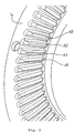
- a plastic ring 4 attached in which a variety of themselves in radial Direction extending grooves 10 is formed.
- the grooves 10 at the top i.e. in the area of the opening, rounded.
- the rounding is carried out and the grooves are positioned in relation to each other in such a way that a in Fig. 2 designated 11, which is between two adjacent grooves near whose radially inward ends is located Rounding radii converge.
- a torque support 100 is also shown in FIG. 1 shown on the vehicle frame, i.e. the Wheelchair frame is attachable.
- the torque arm 100 can also be integrally connected to the wheelchair frame his.
- a thru axle 50 runs through one of the Torque arm 100 attached axle sleeve 110 and through the center of the wheel hub 1.
- FIG. 3 A preferred embodiment of the webs 150 is shown in FIG. 3 shown. 3, the webs are 150 rounded on its top, especially on the radially inner end. Part of the length The web 150 is also provided with a bevel causes the height of the webs at the radially inside lying end is larger than at the radially outer The End.
- the configuration of the webs 150 shown in FIG. 3 results with the design of the grooves shown in Fig. 2 10 a particularly easy insertion of the webs 150 into the Grooves 10.
- the most favorable case of assembly is given, of course, if in the coincidental selected angular position of the drive wheel to Wheelchair frame each bridge 150 exactly with a groove 10 flees.
- the worst case is when the center line 151 of a web 150 is exactly between two grooves 10 is located.
- the center line 151 at the radially inner lying end of the webs 150 at the in Fig. 2 with the Reference numeral 11 designated at which the Radii at the opening of the two side by side Grooves 10 converge.
- Fig. 4 shows an embodiment of a wheel hub with a Thru axle 200, being on the the wheelchair frame facing side of the wheel hub four concentric Contact rings 250, 251, 252 and 253 are provided.
- Four corresponding contact pins 260, 261, 262 and 263 as well a cover plate 270 is shown in FIG. 5.
- the Cover plate 270 serves to cover the contact rings 250, 251, 252 and 253 in operational condition.
- the drive wheel preferably in the peripheral region of the Wheel hub, held and attached in any angular position.
- the thru axle 200 engages in a corresponding one Guide bushing on the wheelchair frame.
- a direct complete axial insertion in axial Direction is possible, which takes place within the by hand held rotor freely rotatable stator due to the special design of the webs and grooves automatically the angular position required for complete insertion on.
- for complete insertion necessary slight twisting of the stator must not caused by turning the wheel hub by hand be, but will when axially touching down and Push in thanks to the special shape of the grooves and bars causes.
Landscapes
- Public Health (AREA)
- Animal Behavior & Ethology (AREA)
- Veterinary Medicine (AREA)
- Life Sciences & Earth Sciences (AREA)
- Health & Medical Sciences (AREA)
- General Health & Medical Sciences (AREA)
- Engineering & Computer Science (AREA)
- Mechanical Engineering (AREA)
- Chemical & Material Sciences (AREA)
- Transportation (AREA)
- Combustion & Propulsion (AREA)
- Arrangement Or Mounting Of Propulsion Units For Vehicles (AREA)
- Road Signs Or Road Markings (AREA)
- Manufacture Of Porous Articles, And Recovery And Treatment Of Waste Products (AREA)
Description
mit mindestens einem Antriebsrad, das abnehmbar auf einer Achse gelagert ist,
wobei das Antriebsrad eine Radnabe und einen im Bereich der Radnabe angeordneten Elektromotor mit einem Stator und einem Rotor aufweist,
wobei der Stator fest mit einem stationären Teil der Radnabe und der Rotor mit einem Umfangsteil der Radnabe, welches sich beim Betrieb des Fahrzeugs dreht, verbunden ist,
mit einer Führungseinrichtung, die es erlaubt, das Antriebsrad in axialer Richtung in seine Betriebsstellung bezüglich des Fahrzeuggestells zu bringen, und
mit einer eine Drehmomentaufnahmeeinrichtung und eine Drehmomentübertragungseinrichtung aufweisenden Drehmomentabstützung, die im betriebsbereiten Zustand des Fahrzeugs durch formschlüssigen Eingriff zwischen einem einzuführenden Element und einem das einzuführende Element aufnehmenden Element ein Drehen des Stators gegenüber dem Fahrzeuggestell verhindert,
wobei das einzuführende Element und das das einzuführende Element aufnehmende Element beim Verschieben des Antriebsrades in axialer Richtung in seine Betriebsstellung bezüglich des Fahrzeuggestells in Eingriff gelangen. Die Erfindung betrifft sowohl Fahrzeuge mit einem Über- oder Untersetzungsgetriebe als auch solche ohne Getriebe.
Claims (12)
- Fahrzeug, insbesondere Rollstuhl,wobei das Antriebsrad eine Radnabe (1) und einen im Bereich der Radnabe (1) angeordneten Elektromotor mit einem Stator und einem Rotor aufweist,mit einem Fahrzeuggestell,mit mindestens einem Antriebsrad, das abnehmbar auf einer Achse (50, 200) gelagert ist,
wobei der Stator fest mit einem stationären Teil (2) der Radnabe (1) und der Rotor mit einem Umfangsteil (3) der Radnabe (1), welches sich beim Betrieb des Fahrzeugs dreht, verbunden ist,
mit einer Führungseinrichtung (50, 110, 200), die es erlaubt, das Antriebsrad in axialer Richtung in seine Betriebsstellung bezüglich des Fahrzeuggestells zu bringen, und
mit einer eine Drehmomentaufnahmeeinrichtung (150) und eine Drehmomentübertragungseinrichtung (10) aufweisenden Drehmomentabstützung, die im betriebsbereiten Zustand des Fahrzeugs durch formschlüssigen Eingriff zwischen einem einzuführenden Element (150) und einem das einzuführende Element aufnehmenden Element (10) ein Drehen des Stators gegenüber dem Fahrzeuggestell verhindert,
wobei das einzuführende Element (150) und das das einzuführende Element aufnehmende Element (10) beim Verschieben des Antriebsrades in axialer Richtung in seine Betriebsstellung bezüglich des Fahrzeuggestells in Eingriff gelangen,
dadurch gekennzeichnet, dass das einzuführende Element (150) und/oder das aufnehmende Element (10) in einer Anzahl größer als eins bereitgestellt sind, so dass ein Anbringen des Antriebsrades an dem Fahrzeuggestell in unterschiedlichen Winkellagen möglich ist. - Fahrzeug nach Anspruch 1, dadurch gekennzeichnet, dass mindestens ein einzuführendes Element (150) an dem Fahrgestell und dass mindestens ein aufnehmendes Element (10) an dem Antriebsrad angeordnet ist.
- Fahrzeug nach Anspruch 1 oder 2, dadurch gekennzeichnet, dass mehrere einzuführende Elemente (150) und mehrere aufnehmende Elemente (10) bereitgestellt sind.
- Fahrzeug nach Anspruch 1, 2 oder 3, dadurch gekennzeichnet, dass das einzuführende Element (150) ein sich radial erstreckender Steg (150) und das aufnehmende Element (10) eine sich radial erstreckende Nut (10) ist.
- Fahrzeug nach Anspruch 4, dadurch gekennzeichnet, dass der Steg (150) an seiner Oberseite zumindest über einen Teil seiner Länge abgerundet ist.
- Fahrzeug nach Anspruch 4 oder 5, dadurch gekennzeichnet, dass der Steg (150) an seiner Oberseite zumindest über einen Teil seiner Länge in radialer Richtung abgeschrägt ist.
- Fahrzeug nach Anspruch 4, 5 oder 6, dadurch gekennzeichnet, dass die Nut (10) an ihrer Oberseite abgerundet ist.
- Fahrzeug nach Anspruch 7, dadurch gekennzeichnet, dass die Radien der abgerundeten Randbereiche zweier nebeneinanderliegender Nuten (10) im Bereich des radial innen liegenden Endes (11) der Nuten (10) zusammenlaufen.
- Fahrzeug nach einem der vorstehenden Ansprüche, dadurch gekennzeichnet, dass das einzuführende Element (150) und das aufnehmende Element (10) in unterschiedlicher Anzahl bereitgestellt sind.
- Fahrzeug nach Anspruch 9, dadurch gekennzeichnet, dass die Anzahl der einzuführenden Elemente (150) kleiner ist als die Anzahl der aufnehmenden Elemente (10).
- Fahrzeug nach Anspruch 10, dadurch gekennzeichnet, dass die Anzahl der einzuführenden Elemente (150) drei beträgt.
- Fahrzeug nach einem der vorstehenden Ansprüche, dadurch gekennzeichnet, dass das aufnehmende Element in einem Kunststoffmaterial ausgebildet ist.
Applications Claiming Priority (2)
| Application Number | Priority Date | Filing Date | Title |
|---|---|---|---|
| DE19949405 | 1999-10-13 | ||
| DE19949405A DE19949405C1 (de) | 1999-10-13 | 1999-10-13 | Fahrzeug, insbesondere Rollstuhl |
Publications (4)
| Publication Number | Publication Date |
|---|---|
| EP1092407A2 EP1092407A2 (de) | 2001-04-18 |
| EP1092407A3 EP1092407A3 (de) | 2002-10-16 |
| EP1092407B1 true EP1092407B1 (de) | 2004-05-12 |
| EP1092407B2 EP1092407B2 (de) | 2007-06-13 |
Family
ID=7925523
Family Applications (1)
| Application Number | Title | Priority Date | Filing Date |
|---|---|---|---|
| EP00121712A Expired - Lifetime EP1092407B2 (de) | 1999-10-13 | 2000-10-04 | Fahrzeug, insbesondere Rollstuhl |
Country Status (4)
| Country | Link |
|---|---|
| EP (1) | EP1092407B2 (de) |
| AT (1) | ATE266372T1 (de) |
| DE (2) | DE19949405C1 (de) |
| DK (1) | DK1092407T4 (de) |
Families Citing this family (6)
| Publication number | Priority date | Publication date | Assignee | Title |
|---|---|---|---|---|
| DE102013109868A1 (de) | 2013-09-10 | 2015-03-12 | Alber Gmbh | Bausatz zur Montage einer Hilfsantriebsvorrichtung an einem Rollstuhl |
| DE102013109863B4 (de) | 2013-09-10 | 2016-11-03 | Alber Gmbh | 2Drehmomentabstützvorrichtung zur Montage eines mit einem Nabenmotor versehenen Antriebsrades an einem Rollstuhl |
| DE102013109865A1 (de) | 2013-09-10 | 2015-03-12 | Alber Gmbh | Steckachse zur Montage eines Rades an einem Rollstuhl |
| EP3173056B1 (de) | 2015-02-04 | 2018-04-11 | Alber GmbH | Vorspannlenkvorrichtung und rollstuhlgespann |
| DE102015102381B4 (de) | 2015-02-19 | 2018-05-30 | Alber Gmbh | Vorspannlenkvorrichtung und Rollstuhlgespann |
| DE102023213239A1 (de) * | 2023-12-21 | 2025-06-26 | Otto Bock Mobility Solutions Gmbh | Rollstuhl |
Family Cites Families (8)
| Publication number | Priority date | Publication date | Assignee | Title |
|---|---|---|---|---|
| US3812928A (en) * | 1972-05-12 | 1974-05-28 | Allis Chalmers | Electric powered wheel |
| DE3924817A1 (de) * | 1989-07-27 | 1991-01-31 | Stehle Josef & Soehne | Antrieb, insbesondere fuer rollstuehle |
| US5161630A (en) * | 1990-09-04 | 1992-11-10 | Fortress Lite-Style, Inc. | Wheelchair drive assembly |
| DE4127257A1 (de) * | 1991-08-17 | 1993-02-18 | Haas & Alber Haustechnik Und A | Kleinfahrzeug, insbesondere rollstuhl mit faltbarem stuhlgestell |
| KR0145431B1 (ko) * | 1992-10-14 | 1998-08-01 | 마스다 쇼오이치로오 | 이동차의 차바퀴 지지장치, 이것을 구비한 이동차 및 이 이동차를 가지는 물품 반송 시스템 |
| US5368122A (en) * | 1993-12-21 | 1994-11-29 | Chou; Wen-Cheng | Electrical bicycle |
| US5472059A (en) * | 1994-02-15 | 1995-12-05 | Dana Corporation | Wheel end assembly |
| DE19708058A1 (de) * | 1997-02-28 | 1998-09-03 | Bock Orthopaed Ind | Muskelbetriebenes Radfahrzeug |
-
1999
- 1999-10-13 DE DE19949405A patent/DE19949405C1/de not_active Expired - Lifetime
-
2000
- 2000-10-04 AT AT00121712T patent/ATE266372T1/de active
- 2000-10-04 DK DK00121712T patent/DK1092407T4/da active
- 2000-10-04 DE DE50006389T patent/DE50006389D1/de not_active Expired - Lifetime
- 2000-10-04 EP EP00121712A patent/EP1092407B2/de not_active Expired - Lifetime
Also Published As
| Publication number | Publication date |
|---|---|
| EP1092407A2 (de) | 2001-04-18 |
| DE19949405C1 (de) | 2000-10-26 |
| EP1092407A3 (de) | 2002-10-16 |
| DK1092407T3 (da) | 2004-09-20 |
| ATE266372T1 (de) | 2004-05-15 |
| DK1092407T4 (da) | 2007-07-16 |
| EP1092407B2 (de) | 2007-06-13 |
| DE50006389D1 (de) | 2004-06-17 |
Similar Documents
| Publication | Publication Date | Title |
|---|---|---|
| EP4294701B1 (de) | Lenksäule für ein kraftfahrzeug | |
| EP2627483B1 (de) | Handgeführtes elektrowerkzeug mit einer spindellockvorrichtung | |
| EP3500476A1 (de) | Steuerhorn für die lenkung eines kaftfahrzeugs | |
| DE19861127A1 (de) | Hilfsantriebsvorrichtung für Selbstfahrer-Rollstühle | |
| DE4011947A1 (de) | Fahrzeug-lenksystem | |
| WO2019137875A1 (de) | Lenkrad eines kraftfahrzeugs | |
| EP4015848B1 (de) | Seilantriebsvorrichtung eines kraftfahrzeugs | |
| DE2925781A1 (de) | Verstellvorrichtung fuer eine kopfstuetze eines kraftfahrzeugsitzes | |
| DE29722592U1 (de) | Spielzeugauto mit beweglichem vorderen Ende | |
| DE102016118032A1 (de) | Antriebseinheit und Rollstuhl mit Antriebseinheit | |
| EP2632768B1 (de) | Lenkeinrichtung für kraftfahrzeuge | |
| DE102016215843A1 (de) | Lenkrad zum Betätigen einer Lenkbewegung eines Fahrzeuges | |
| EP1092407B2 (de) | Fahrzeug, insbesondere Rollstuhl | |
| DE102004039057B3 (de) | Untersetzungsgetriebe und dieses verwendende Antriebseinheit | |
| DE3443625C2 (de) | ||
| EP1425206A1 (de) | Anordnung bestehend aus einem lenkrad und einem torsionsmodul | |
| EP0314887A1 (de) | Lenkvorrichtung für Fahrzeuge | |
| DE102021200644A1 (de) | Lenkrad für eine Kraftfahrzeuglenkung | |
| EP0846596B1 (de) | Aussenspiegelgelenk | |
| EP0697546B1 (de) | Getriebe für einen mit Federrücklauf ausgerüsteten Stellantrieb | |
| DE3332040A1 (de) | Gelenkarmmechanismus | |
| DE102021213561A1 (de) | Transformationsrad und Robotersystem | |
| DE102008016970B3 (de) | Lenkvorrichtung für ein Kraftfahrzeug mit einem Lenkrad und einem Überlagerungsgetriebe | |
| DE69829051T2 (de) | Vorrichtung zum steuern der winkelstellung eines fahrzeugaussenrückblickspiegels | |
| DE3822968A1 (de) | Kippstaenderanordnung fuer motorraeder |
Legal Events
| Date | Code | Title | Description |
|---|---|---|---|
| PUAI | Public reference made under article 153(3) epc to a published international application that has entered the european phase |
Free format text: ORIGINAL CODE: 0009012 |
|
| AK | Designated contracting states |
Kind code of ref document: A2 Designated state(s): AT BE CH CY DE DK ES FI FR GB GR IE IT LI LU MC NL PT SE |
|
| AX | Request for extension of the european patent |
Free format text: AL;LT;LV;MK;RO;SI |
|
| PUAL | Search report despatched |
Free format text: ORIGINAL CODE: 0009013 |
|
| AK | Designated contracting states |
Kind code of ref document: A3 Designated state(s): AT BE CH CY DE DK ES FI FR GB GR IE IT LI LU MC NL PT SE |
|
| AX | Request for extension of the european patent |
Free format text: AL;LT;LV;MK;RO;SI |
|
| 17P | Request for examination filed |
Effective date: 20021029 |
|
| 17Q | First examination report despatched |
Effective date: 20030211 |
|
| RAP1 | Party data changed (applicant data changed or rights of an application transferred) |
Owner name: ULRICH ALBER GMBH & CO. KG |
|
| AKX | Designation fees paid |
Designated state(s): AT BE CH CY DE DK ES FI FR GB GR IE IT LI LU MC NL PT SE |
|
| GRAP | Despatch of communication of intention to grant a patent |
Free format text: ORIGINAL CODE: EPIDOSNIGR1 |
|
| GRAS | Grant fee paid |
Free format text: ORIGINAL CODE: EPIDOSNIGR3 |
|
| GRAA | (expected) grant |
Free format text: ORIGINAL CODE: 0009210 |
|
| AK | Designated contracting states |
Kind code of ref document: B1 Designated state(s): AT BE CH CY DE DK ES FI FR GB GR IE IT LI LU MC NL PT SE |
|
| PG25 | Lapsed in a contracting state [announced via postgrant information from national office to epo] |
Ref country code: IT Free format text: LAPSE BECAUSE OF FAILURE TO SUBMIT A TRANSLATION OF THE DESCRIPTION OR TO PAY THE FEE WITHIN THE PRESCRIBED TIME-LIMIT;WARNING: LAPSES OF ITALIAN PATENTS WITH EFFECTIVE DATE BEFORE 2007 MAY HAVE OCCURRED AT ANY TIME BEFORE 2007. THE CORRECT EFFECTIVE DATE MAY BE DIFFERENT FROM THE ONE RECORDED. Effective date: 20040512 Ref country code: FI Free format text: LAPSE BECAUSE OF FAILURE TO SUBMIT A TRANSLATION OF THE DESCRIPTION OR TO PAY THE FEE WITHIN THE PRESCRIBED TIME-LIMIT Effective date: 20040512 Ref country code: CY Free format text: LAPSE BECAUSE OF FAILURE TO SUBMIT A TRANSLATION OF THE DESCRIPTION OR TO PAY THE FEE WITHIN THE PRESCRIBED TIME-LIMIT Effective date: 20040512 |
|
| REG | Reference to a national code |
Ref country code: GB Ref legal event code: FG4D Free format text: NOT ENGLISH |
|
| REG | Reference to a national code |
Ref country code: CH Ref legal event code: EP |
|
| REG | Reference to a national code |
Ref country code: IE Ref legal event code: FG4D Free format text: GERMAN |
|
| REF | Corresponds to: |
Ref document number: 50006389 Country of ref document: DE Date of ref document: 20040617 Kind code of ref document: P |
|
| REG | Reference to a national code |
Ref country code: CH Ref legal event code: NV Representative=s name: ZIMMERLI, WAGNER & PARTNER AG |
|
| REG | Reference to a national code |
Ref country code: SE Ref legal event code: TRGR |
|
| GBT | Gb: translation of ep patent filed (gb section 77(6)(a)/1977) |
Effective date: 20040719 |
|
| PG25 | Lapsed in a contracting state [announced via postgrant information from national office to epo] |
Ref country code: GR Free format text: LAPSE BECAUSE OF FAILURE TO SUBMIT A TRANSLATION OF THE DESCRIPTION OR TO PAY THE FEE WITHIN THE PRESCRIBED TIME-LIMIT Effective date: 20040812 |
|
| PG25 | Lapsed in a contracting state [announced via postgrant information from national office to epo] |
Ref country code: ES Free format text: LAPSE BECAUSE OF FAILURE TO SUBMIT A TRANSLATION OF THE DESCRIPTION OR TO PAY THE FEE WITHIN THE PRESCRIBED TIME-LIMIT Effective date: 20040823 |
|
| REG | Reference to a national code |
Ref country code: DK Ref legal event code: T3 |
|
| PG25 | Lapsed in a contracting state [announced via postgrant information from national office to epo] |
Ref country code: LU Free format text: LAPSE BECAUSE OF NON-PAYMENT OF DUE FEES Effective date: 20041004 |
|
| PGFP | Annual fee paid to national office [announced via postgrant information from national office to epo] |
Ref country code: BE Payment date: 20041025 Year of fee payment: 5 |
|
| PG25 | Lapsed in a contracting state [announced via postgrant information from national office to epo] |
Ref country code: MC Free format text: LAPSE BECAUSE OF NON-PAYMENT OF DUE FEES Effective date: 20041031 |
|
| ET | Fr: translation filed | ||
| PLAQ | Examination of admissibility of opposition: information related to despatch of communication + time limit deleted |
Free format text: ORIGINAL CODE: EPIDOSDOPE2 |
|
| PLBQ | Unpublished change to opponent data |
Free format text: ORIGINAL CODE: EPIDOS OPPO |
|
| PLAQ | Examination of admissibility of opposition: information related to despatch of communication + time limit deleted |
Free format text: ORIGINAL CODE: EPIDOSDOPE2 |
|
| PLAR | Examination of admissibility of opposition: information related to receipt of reply deleted |
Free format text: ORIGINAL CODE: EPIDOSDOPE4 |
|
| PLBQ | Unpublished change to opponent data |
Free format text: ORIGINAL CODE: EPIDOS OPPO |
|
| PLBI | Opposition filed |
Free format text: ORIGINAL CODE: 0009260 |
|
| PLAX | Notice of opposition and request to file observation + time limit sent |
Free format text: ORIGINAL CODE: EPIDOSNOBS2 |
|
| REG | Reference to a national code |
Ref country code: CH Ref legal event code: PFA Owner name: ULRICH ALBER GMBH Free format text: ULRICH ALBER GMBH & CO. KG#VOR DEM WEISSEN STEIN 21#72461 ALBSTADT-TAILFINGEN (DE) -TRANSFER TO- ULRICH ALBER GMBH#VOR DEM WEISSEN STEIN 21#72461 ALBSTADT-TAILFINGEN (DE) |
|
| 26 | Opposition filed |
Opponent name: SUNRISE MEDICAL GLOBAL ADVANCED ENGINEERING Effective date: 20050211 |
|
| RAP2 | Party data changed (patent owner data changed or rights of a patent transferred) |
Owner name: ULRICH ALBER GMBH |
|
| NLS | Nl: assignments of ep-patents |
Owner name: ULRICH ALBER GMBH |
|
| NLR1 | Nl: opposition has been filed with the epo |
Opponent name: SUNRISE MEDICAL GLOBAL ADVANCED ENGINEERING |
|
| NLT2 | Nl: modifications (of names), taken from the european patent patent bulletin |
Owner name: ULRICH ALBER GMBH |
|
| PLBB | Reply of patent proprietor to notice(s) of opposition received |
Free format text: ORIGINAL CODE: EPIDOSNOBS3 |
|
| REG | Reference to a national code |
Ref country code: FR Ref legal event code: CD Ref country code: FR Ref legal event code: CJ |
|
| PG25 | Lapsed in a contracting state [announced via postgrant information from national office to epo] |
Ref country code: BE Free format text: LAPSE BECAUSE OF NON-PAYMENT OF DUE FEES Effective date: 20051031 |
|
| REG | Reference to a national code |
Ref country code: FR Ref legal event code: ST Effective date: 20060630 |
|
| PUAH | Patent maintained in amended form |
Free format text: ORIGINAL CODE: 0009272 |
|
| STAA | Information on the status of an ep patent application or granted ep patent |
Free format text: STATUS: PATENT MAINTAINED AS AMENDED |
|
| 27A | Patent maintained in amended form |
Effective date: 20070613 |
|
| AK | Designated contracting states |
Kind code of ref document: B2 Designated state(s): AT BE CH CY DE DK ES FI FR GB GR IE IT LI LU MC NL PT SE |
|
| REG | Reference to a national code |
Ref country code: FR Ref legal event code: D3 |
|
| REG | Reference to a national code |
Ref country code: CH Ref legal event code: AEN Free format text: AUFRECHTERHALTUNG DES PATENTES IN GEAENDERTER FORM |
|
| REG | Reference to a national code |
Ref country code: ES Ref legal event code: FD2A Effective date: 20041005 Ref country code: DK Ref legal event code: T4 |
|
| GBTA | Gb: translation of amended ep patent filed (gb section 77(6)(b)/1977) | ||
| NLR2 | Nl: decision of opposition |
Effective date: 20070613 |
|
| REG | Reference to a national code |
Ref country code: SE Ref legal event code: RPEO |
|
| NLR3 | Nl: receipt of modified translations in the netherlands language after an opposition procedure | ||
| ET3 | Fr: translation filed ** decision concerning opposition | ||
| BERE | Be: lapsed |
Owner name: ULRICH *ALBER G.M.B.H. & CO. K.G. Effective date: 20051031 |
|
| PG25 | Lapsed in a contracting state [announced via postgrant information from national office to epo] |
Ref country code: PT Free format text: LAPSE BECAUSE OF NON-PAYMENT OF DUE FEES Effective date: 20041012 |
|
| REG | Reference to a national code |
Ref country code: IE Ref legal event code: MM4A |
|
| PGFP | Annual fee paid to national office [announced via postgrant information from national office to epo] |
Ref country code: IE Payment date: 20071010 Year of fee payment: 8 |
|
| PG25 | Lapsed in a contracting state [announced via postgrant information from national office to epo] |
Ref country code: IE Free format text: LAPSE BECAUSE OF NON-PAYMENT OF DUE FEES Effective date: 20081006 |
|
| REG | Reference to a national code |
Ref country code: CH Ref legal event code: PFA Owner name: ULRICH ALBER GMBH Free format text: ULRICH ALBER GMBH#VOR DEM WEISSEN STEIN 21#72461 ALBSTADT-TAILFINGEN (DE) -TRANSFER TO- ULRICH ALBER GMBH#VOR DEM WEISSEN STEIN 21#72461 ALBSTADT-TAILFINGEN (DE) |
|
| REG | Reference to a national code |
Ref country code: CH Ref legal event code: NV Representative=s name: WAGNER PATENT AG, CH |
|
| REG | Reference to a national code |
Ref country code: DE Ref legal event code: R082 Ref document number: 50006389 Country of ref document: DE Representative=s name: STAUDT IP LAW, DE |
|
| REG | Reference to a national code |
Ref country code: FR Ref legal event code: PLFP Year of fee payment: 16 |
|
| REG | Reference to a national code |
Ref country code: FR Ref legal event code: PLFP Year of fee payment: 17 |
|
| REG | Reference to a national code |
Ref country code: FR Ref legal event code: PLFP Year of fee payment: 18 |
|
| REG | Reference to a national code |
Ref country code: FR Ref legal event code: PLFP Year of fee payment: 19 |
|
| PGFP | Annual fee paid to national office [announced via postgrant information from national office to epo] |
Ref country code: NL Payment date: 20181022 Year of fee payment: 19 |
|
| PGFP | Annual fee paid to national office [announced via postgrant information from national office to epo] |
Ref country code: DK Payment date: 20181025 Year of fee payment: 19 Ref country code: AT Payment date: 20181019 Year of fee payment: 19 Ref country code: SE Payment date: 20181025 Year of fee payment: 19 Ref country code: DE Payment date: 20181015 Year of fee payment: 19 |
|
| PGFP | Annual fee paid to national office [announced via postgrant information from national office to epo] |
Ref country code: GB Payment date: 20181025 Year of fee payment: 19 Ref country code: FR Payment date: 20181023 Year of fee payment: 19 Ref country code: CH Payment date: 20181025 Year of fee payment: 19 |
|
| REG | Reference to a national code |
Ref country code: DE Ref legal event code: R119 Ref document number: 50006389 Country of ref document: DE |
|
| REG | Reference to a national code |
Ref country code: DK Ref legal event code: EBP Effective date: 20191031 |
|
| REG | Reference to a national code |
Ref country code: CH Ref legal event code: PL |
|
| REG | Reference to a national code |
Ref country code: NL Ref legal event code: MM Effective date: 20191101 |
|
| PG25 | Lapsed in a contracting state [announced via postgrant information from national office to epo] |
Ref country code: CH Free format text: LAPSE BECAUSE OF NON-PAYMENT OF DUE FEES Effective date: 20191031 Ref country code: LI Free format text: LAPSE BECAUSE OF NON-PAYMENT OF DUE FEES Effective date: 20191031 Ref country code: DE Free format text: LAPSE BECAUSE OF NON-PAYMENT OF DUE FEES Effective date: 20200501 |
|
| REG | Reference to a national code |
Ref country code: AT Ref legal event code: MM01 Ref document number: 266372 Country of ref document: AT Kind code of ref document: T Effective date: 20191004 |
|
| PG25 | Lapsed in a contracting state [announced via postgrant information from national office to epo] |
Ref country code: SE Free format text: LAPSE BECAUSE OF NON-PAYMENT OF DUE FEES Effective date: 20191005 Ref country code: NL Free format text: LAPSE BECAUSE OF NON-PAYMENT OF DUE FEES Effective date: 20191101 |
|
| GBPC | Gb: european patent ceased through non-payment of renewal fee |
Effective date: 20191004 |
|
| PG25 | Lapsed in a contracting state [announced via postgrant information from national office to epo] |
Ref country code: FR Free format text: LAPSE BECAUSE OF NON-PAYMENT OF DUE FEES Effective date: 20191031 Ref country code: GB Free format text: LAPSE BECAUSE OF NON-PAYMENT OF DUE FEES Effective date: 20191004 Ref country code: DK Free format text: LAPSE BECAUSE OF NON-PAYMENT OF DUE FEES Effective date: 20191031 |
|
| PG25 | Lapsed in a contracting state [announced via postgrant information from national office to epo] |
Ref country code: AT Free format text: LAPSE BECAUSE OF NON-PAYMENT OF DUE FEES Effective date: 20191004 |