EP1092081B1 - Rotor for a turbomachine - Google Patents
Rotor for a turbomachine Download PDFInfo
- Publication number
- EP1092081B1 EP1092081B1 EP99939943A EP99939943A EP1092081B1 EP 1092081 B1 EP1092081 B1 EP 1092081B1 EP 99939943 A EP99939943 A EP 99939943A EP 99939943 A EP99939943 A EP 99939943A EP 1092081 B1 EP1092081 B1 EP 1092081B1
- Authority
- EP
- European Patent Office
- Prior art keywords
- flange
- rotor
- accordance
- several
- recesses
- Prior art date
- Legal status (The legal status is an assumption and is not a legal conclusion. Google has not performed a legal analysis and makes no representation as to the accuracy of the status listed.)
- Expired - Lifetime
Links
Images


Classifications
-
- F—MECHANICAL ENGINEERING; LIGHTING; HEATING; WEAPONS; BLASTING
- F01—MACHINES OR ENGINES IN GENERAL; ENGINE PLANTS IN GENERAL; STEAM ENGINES
- F01D—NON-POSITIVE DISPLACEMENT MACHINES OR ENGINES, e.g. STEAM TURBINES
- F01D5/00—Blades; Blade-carrying members; Heating, heat-insulating, cooling or antivibration means on the blades or the members
- F01D5/02—Blade-carrying members, e.g. rotors
- F01D5/06—Rotors for more than one axial stage, e.g. of drum or multiple disc type; Details thereof, e.g. shafts, shaft connections
- F01D5/066—Connecting means for joining rotor-discs or rotor-elements together, e.g. by a central bolt, by clamps
Definitions
- the invention relates to a rotor for a turbomachine, with at least two bladed Steps whose discs are detachably connected to each other.
- Turbomachinery rotors generally have a plurality of vaned blades Stages whose discs in different ways, e.g. by welding or releasably connected by screwing, with each other. Present will be considered only releasably interconnected stages.
- the discs are substantially in the axial direction extending, cylindrical or conical shells on, at the end portions thereof each disc-annular flanges are provided, to which adjacent Slices with screws, stud bolts od. Like. Are connected. If one Interstage seal is not integrated in the shells, it is between each sandwiched the flanges. Such a connection can only be at Relatively low peripheral speed components, e.g. slowly running low-pressure turbines, use as the centrifugal forces at for high peripheral speeds designed discs too high hoop stresses in the flange connection. The holes in the flanges make local Voltage increments causing notching and restrict the cyclic Durable life of the component.
- DE-OS 2 104 172 discloses a turbine rotor and a method for its production, at the adjacent discs with inwardly directed flanges with aligned bolt holes through which a bolt is passed, clamped together are.
- the problem is that the bolt holes in the Flange represent local stress risers causing notching and the limit cyclic life of the rotor.
- a disc In a further known rotor, a disc has bores through which with adjacent discs, with cylindrical or conical shells with Have flanges, is connected by screwing.
- the disk body limited the radial expansion of the joint due to centrifugal force.
- the problem is that the holes in the highly loaded disk body represent life-limiting notch sites.
- the invention has for its object to provide a rotor for a turbomachine to create the genus described above, in which the discs detachable with each other be connected without extreme voltage increases by notching occur in the disc.
- the first flange extends axially spaced from the side surface of first disc to form a gap radially inward.
- the first flange is designed as a disc ring, which has recesses along its inner end or peripheral edge.
- the recesses are opened inwards, so that through the bolts generated centrifugal force can be absorbed by the edge surface of the recesses can.
- the recesses are equidistant along the peripheral edge are arranged.
- a slot or another recess can be provided.
- a flange portion of an intermediate stage seal is between each the first and second flange clamped, wherein the flange portion of the Interstage seal preferred to the recesses of the first flange has aligned bores, which the bolts in the radial direction during assembly fix.
- the bolts facing at their the first disc Ends a transverse section extending at right angles to its longitudinal axis have, with which they are supported on an inner side surface of the first flange.
- the bolts are preferably T-head bolts.
- the distance of the first flange to the side surface of the first disc as small as possible, but larger than the thickness of the transverse section of the bolt to to avoid a pressure point on the highly loaded, first disc.
- the flange of an adjacent disc has at its radially inner end a substantially axially extending support portion on, on which the cross section of the bolt is supported, so as to prevent rotation to create a bolt.
- the first disc on both side surfaces a first flange, so that in this way, the discs of rotors detachably connect with more than two levels.
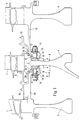
- Fig. 1 shows a longitudinal section of an embodiment of the invention Rotor for a turbomachine, which has three stages.
- the steps are each with a blade 1, 2 and 3 and a first disc 4 and two adjacent Slices 5,6 provided.
- the first disc 4 has at its two side surfaces 7,8 each have a flange 9 and 10, respectively.
- the flanges 9,10 extend with a axial distance A from their inner side surfaces 11,12 to the side surfaces 7,8 the first disc 4. In this way, between the first disc 4 and the Flanges 9,10 a gap Z, which is open in the radial direction inwards.
- the distance A is to be kept as small as possible, around the radial expansion of the flanges 9,10 and the flange to be limited by the body of the disc 4.
- a transverse section 13 engages (Screw) bolt 14 in the space Z and rests on the Tensioning / bolting respectively to the inner side surface such as e.g. 12, the Flange 10 from.
- the disks 5, 6 adjacent to the middle, first disk 4 each face each other extending substantially in the axial direction, cylindrical shells 16, which also may be formed cone-shaped.
- the bowls 16 have on their to the Slices 5.6 distal ends each have a second flange 17, each with the Flanges 9,10 of the first disc 4 by (screw) bolt 14 or the like. tightly clamped becomes.
- the second flanges 17 of the disks 5, 6 are each closed substantially in the axial direction extending support portion 18 at which the Transverse portions 13 of the bolts 14 can be supported, whereby a rotation of the bolt 14 is prevented. This ensures that when mounting or tightening the (screw) bolt 14 no pressure points on the highly loaded, first discs 4 occur.
- each intermediate stage seal 19 with her Flange portion 20 clamped and releasably secured.
- the intermediate stage seals Alternatively, 19 may also be integral with the discs 5, 6 or their shells 16 may be arranged.
- Fig. 2 shows a cut and broken cross-sectional view along the line II-II of Fig. 1, in the upper partial section of the flange 9 shown in a plan view is.
- the flange 9 is formed as a disc ring, on the inner Stir n-area or peripheral edge 21 in the radial direction inwardly open, slot-like Recesses 15 are provided.
- a recess 15 is a (screw) bolt 14 used, the transverse section 13 is shown in dashed lines. After mo n-ting this is supported on the inner side surface 11 of the flange 9.
- a bore 22 provided for relief, which the notch factor due to the recess 15th decreases.
- the holes 22 as slots, more Au savings savings or the like. be educated.
- Fig. 2 In the lower part of Fig. 2 is the disc-ring-shaped Flange portion 20 of the intermediate stage seal 19 shown, the holes 23rd having.
- the holes 23 are aligned with the recesses 15 in the flanges 9,10 of the first disc 4 as well as corresponding holes 24 in the second Flanges 17 from the adjacent to the first disc 4 discs 5.6.
- the holes 23 in the flange portion 20 of the interstage seal 19 radially inwardly open, with their opening size smaller than her Diameter is so as to a radial fixation of the (screw) bolt 14 in the To assure assembly.
- the holes 23 as closed Be formed holes.
- every second stage will have one less a flange 9 and 10 having the first disc 4 provided.
- Fig. 3 shows a further embodiment of the rotor according to the invention, in the radius R at the transition between the inner side surface 8 of the first Slice 4 and the flange 10 and its inner side surface 12 of strength s-found is enlarged.
- the distance A between the side surface 8 of the first disc 4 and the inner side surface 12 of the flange 10 is larger, has the (screw) bolt 14 a shear ring or collar 25, which on an outer Side surface 26 of the flange 10 rests and an axial displacement of the (Screw) bolt 14 prevents so that the transverse sections 13 during assembly not be pressed against the first disc 4 and e-hen their protection against Verdr to lose.
Description
Die Erfindung betrifft einen Rotor für eine Turbomaschine, mit wenigstens zwei beschaufelten Stufen, deren Scheiben lösbar miteinander verbunden sind.The invention relates to a rotor for a turbomachine, with at least two bladed Steps whose discs are detachably connected to each other.
Rotoren von Turbomaschinen weisen im allgemeinen mehrere, mit Schaufeln versehene Stufen auf, deren Scheiben auf unterschiedliche Weise, z.B. durch Schweißen oder lösbar durch Verschrauben, miteinander verbunden sind. Vorliegend werden lediglich lösbar miteinander verbundene Stufen betrachtet.Turbomachinery rotors generally have a plurality of vaned blades Stages whose discs in different ways, e.g. by welding or releasably connected by screwing, with each other. Present will be considered only releasably interconnected stages.
Bei einem bekannten Rotor weisen die Scheiben sich im wesentlichen in Axialrichtung erstreckende, zylindrische oder kegelförmige Schalen auf, an deren Endabschnitten jeweils scheibenringförmige Flansche vorgesehen sind, an welchen benachbarte Scheiben mit Schrauben, Stehbolzen od. dgl. verbunden sind. Sofern eine Zwischenstufendichtung nicht in den Schalen integriert ist, wird sie jeweils zwischen den Flanschen eingeklemmt. Eine derartige Verbindungsart läßt sich lediglich bei Komponenten mit verhältnismäßig niedriger Umfangsgeschwindigkeit, wie z.B. langsam laufende Niederdruckturbinen, einsetzen, da die auftretenden Fliehkräfte bei für hohe Umfangsgeschwindigkeiten ausgelegten Scheiben zu hohe Umfangsspannungen in der Flanschverbindung erzeugen. Die Bohrungen in den Flanschen stellen lokale Spannungserhöhungen verursachende Kerbstellen dar und schränken die zyklische Lebensdauer des Bauteils stark ein.In a known rotor, the discs are substantially in the axial direction extending, cylindrical or conical shells on, at the end portions thereof each disc-annular flanges are provided, to which adjacent Slices with screws, stud bolts od. Like. Are connected. If one Interstage seal is not integrated in the shells, it is between each sandwiched the flanges. Such a connection can only be at Relatively low peripheral speed components, e.g. slowly running low-pressure turbines, use as the centrifugal forces at for high peripheral speeds designed discs too high hoop stresses in the flange connection. The holes in the flanges make local Voltage increments causing notching and restrict the cyclic Durable life of the component.
Die DE 196 27 386 A1 offenbart eine Verbindungs-Anordnung für zwei Turbinen-Laufradscheiben, die jeweils Scheiben-Verbindungsarme mit Durchsteckbohrungen aufweisen, in welche besonders ausgestaltete Gewindebolzen zur Verbindung der Laufradscheiben eingesetzt werden. Insbesondere bei hohen Umfangsgeschwindigkeiten erweist sich als nachteilig, daß eine radiale Aufweitung der Flanschverbindung infolge der Fliehkraftwirkung auftritt.DE 196 27 386 A1 discloses a connection arrangement for two turbine impeller disks, the respective disc connecting arms with through holes in which specially designed threaded bolt for connecting the Impeller disks are used. Especially at high peripheral speeds proves to be disadvantageous that a radial expansion of the flange connection due to the centrifugal effect occurs.
Aus der US 5,388,963 ist ein Rotor für Verdichter von Gasturbinen bekannt, bei dem benachbarte Scheiben durch Flansche lösbar verbunden sind, wobei ein erster Flansch Schlitze und ein zweiter Flansch Löcher zur Aufnahme von Verbindungsbolzen aufweist, und wobei eine separate Klammer mit gegenüberliegendem biegbaren Zungen eingesetzt wird, um ein Drehen des Verbindungsbolzen bei der Montage und Demontage zu verhindern.From US 5,388,963 a rotor for compressors of gas turbines is known in which adjacent discs are detachably connected by flanges, wherein a first Flange slots and a second flange holes for receiving connecting bolts and wherein a separate clip with opposite bendable Tongues is used to rotate the connecting bolt during assembly and Disassembly to prevent.
Die DE-OS 2 104 172 offenbart einen Turbinenrotor und ein Verfahren zu seiner Herstellung, bei dem benachbarte Scheiben über nach innen gerichtete Flansche mit fluchtenden Bolzenbohrungen, durch die jeweils ein Bolzen hindurchgeführt ist, zusammengeklemmt sind. Problematisch dabei ist, dass die Bolzenbohrungen in dem Flansch lokale Spannungserhöhungen verursachende Kerbstellen darstellen und die zyklische Lebensdauer des Rotors einschränken.DE-OS 2 104 172 discloses a turbine rotor and a method for its production, at the adjacent discs with inwardly directed flanges with aligned bolt holes through which a bolt is passed, clamped together are. The problem is that the bolt holes in the Flange represent local stress risers causing notching and the limit cyclic life of the rotor.
Aus der US 5,350,278 ist eine Anordnung von beabstandeten Rotorscheiben bekannt, die über an Abstandshaltern vorgesehenen Flanschen lösbar miteinander verschraubt sind, wobei durch die Abstandshalter ein ringförmiger Raum entlang eines Scheibenpaars zur strukturellen Abstützung definiert wird. Für das Verschrauben sind in den Flanschen Bohrungen vorgesehen, die Kerbstellen darstellen.From US 5,350,278 an arrangement of spaced rotor disks is known, the detachably provided on spacers flanges screwed together are, wherein by the spacers an annular space along a Disc pair is defined for structural support. For screwing are provided in the flanges holes that represent notches.
Bei schnellaufenden Niederdruckturbinen sind bspw. an den Zwischenstufendichtungen zusätzliche, sich radial nach innen erstreckende Scheiben vorgesehen worden. In high-speed low-pressure turbines are, for example, at the interstage seals additional, radially inwardly extending discs have been provided.
Auf diese Weise soll die radiale Aufweitung so begrenzt werden, daß die entstehenden Umfangsspannungen infolge der Fliehkraftwirkungen auf einem niedrigen Niveau gehalten werden und die geforderte zyklische Lebensdauer erreicht wird. Die zusätzlichen Scheiben führen jedoch zu erheblichen Gewichtsnachteilen und Problemen bei der Montage.In this way, the radial expansion is to be limited so that the resulting Hoop stresses due to the centrifugal force effects at a low level be maintained and the required cyclic life is achieved. The additional Slices, however, lead to significant weight penalties and problems the assembly.
Bei einem weiteren bekannten Rotor weist eine Scheibe Bohrungen auf, durch welche sie mit benachbarten Scheiben, die zylindrische oder kegelförmige Schalen mit Flanschen aufweisen, durch Verschrauben verbunden wird. Der Scheibenkörper begrenzt die radiale Aufweitung der Verbindungsstelle infolge von Fliehkraftwirkung. Problematisch ist jedoch, daß die Bohrungen in dem hochbelasteten Scheibenkörper lebensdauerbegrenzende Kerbstellen darstellen.In a further known rotor, a disc has bores through which with adjacent discs, with cylindrical or conical shells with Have flanges, is connected by screwing. The disk body limited the radial expansion of the joint due to centrifugal force. The problem, however, is that the holes in the highly loaded disk body represent life-limiting notch sites.
Aus der US 4,844,694 ist eine Verbindung von Rotorelementen einer Gasturbine bekannt, bei der die an der Verbindungsstelle liegende Scheibe eine Bohrung zum Einsetzen eines Bolzens aufweist, wobei die Bohrungen in dem hochbelasteten Scheibenkörper lebensdauerbegrenzende Kerbstellen darstellen. Letztgenannter Nachteil ist auch bei der in der US 5,052,891 offenbarten Bolzenverbindung zwischen Rotorelementen einer Gasturbine gegeben, bei welcher in der an der Verbindungsstelle liegenden Scheibe eine Bohrung für die Bolzenverbindung vorgesehen ist.From US 4,844,694 is a compound of rotor elements of a gas turbine known, in which the disc lying at the junction a bore for Insertion of a bolt, wherein the holes in the highly loaded Disc body represent life-limiting Kerbstellen. The latter Disadvantage is also in the disclosed in US 5,052,891 bolt connection between Given rotor elements of a gas turbine, in which at the junction lying disc provided a bore for the bolt connection is.
Der Erfindung liegt die Aufgabe zugrunde, einen Rotor für eine Turbomaschine der eingangs beschriebenen Gattung zu schaffen, bei dem die Scheiben lösbar miteinander verbunden werden, ohne daß extreme Spannungserhöhungen durch Kerbstellen in der Scheibe auftreten.The invention has for its object to provide a rotor for a turbomachine to create the genus described above, in which the discs detachable with each other be connected without extreme voltage increases by notching occur in the disc.
Die Lösung der Aufgabe ist erfindungsgemäß durch die Kennzeichnenden Merkmale von Anspruch 1 gekennzeichnet. The solution of the problem is characterized according to the invention by the characterizing features of claim 1.
Der Vorteil einer solchen Ausgestaltung besteht darin, daß die radiale Aufweitung der Flanschverbindung durch den Scheibenkörper begrenzt wird, die Scheibe selbst jedoch keine Bohrungen bzw. Kerbstellen aufweist, welche die zum Teil extrem hohen, lokalen Spannungserhöhungen verursachen.The advantage of such an embodiment is that the radial expansion the flange connection is limited by the disk body, the disk itself However, there are no holes or notch locations, some of which are extremely high, cause local voltage increases.
Bevorzugt erstreckt sich der erste Flansch mit axialem Abstand zur Seitenfläche der ersten Scheibe unter Bildung eines Zwischenraums radial nach innen.Preferably, the first flange extends axially spaced from the side surface of first disc to form a gap radially inward.
Der erste Flansch ist als Scheibenring ausgebildet, der entlang seiner inneren Stirn- bzw. Umfangskante Aussparungen aufweist.The first flange is designed as a disc ring, which has recesses along its inner end or peripheral edge.
Die Aussparungen sind nach innen geöffnet, damit die durch die Bolzen erzeugte Fliehkraft durch die Randfläche der Aussparungen aufgenommen werden kann.The recesses are opened inwards, so that through the bolts generated centrifugal force can be absorbed by the edge surface of the recesses can.
Ferner ist vorteilhaft, daß die Aussparungen äquidistant entlang der Umfangskante angeordnet sind.Furthermore, it is advantageous that the recesses are equidistant along the peripheral edge are arranged.
Zur Reduzierung der Kerbwirkung kann zwischen den Aussparungen jeweils eine Bohrung, ein Langloch oder eine weitere Aussparung vorgesehen werden.To reduce the notch effect can between the recesses one each Bore, a slot or another recess can be provided.
Höchst bevorzugt ist ein Flanschabschnitt einer Zwischenstufendichtung jeweils zwischen dem ersten und zweiten Flansch eingeklemmt, wobei der Flanschabschnitt der Zwischenstufendichtung bevorzugt zu den Aussparungen des ersten Flansches fluchtende Bohrungen aufweist, welche die Bolzen in Radialrichtung bei der Montage fixieren.Most preferably, a flange portion of an intermediate stage seal is between each the first and second flange clamped, wherein the flange portion of the Interstage seal preferred to the recesses of the first flange has aligned bores, which the bolts in the radial direction during assembly fix.
Es ist ferner zweckmäßig, daß die Bolzen an ihren der ersten Scheibe zugewandten Enden einen sich rechtwinklig zu ihrer Längsachse erstreckenden Querabschnitt aufweisen, mit dem sie sich an einer inneren Seitenfläche des ersten Flansches abstützen. Bevorzugt sind die Bolzen T-Kopf-Bolzen. It is also expedient that the bolts facing at their the first disc Ends a transverse section extending at right angles to its longitudinal axis have, with which they are supported on an inner side surface of the first flange. The bolts are preferably T-head bolts.
Bevorzugt ist der Abstand des ersten Flansches zur Seitenfläche der ersten Scheibe möglichst gering, jedoch größer als die Stärke des Querabschnitts des Bolzens, um eine Druckstelle an der hochbelasteten, ersten Scheibe zu vermeiden.Preferably, the distance of the first flange to the side surface of the first disc as small as possible, but larger than the thickness of the transverse section of the bolt to to avoid a pressure point on the highly loaded, first disc.
Der Flansch einer benachbarten Scheibe weist an seinem radial inneren Ende einen sich im wesentlichen in Axialrichtung erstreckender Stützabschnitt auf, an dem sich der Querabschnitt der Bolzen abstützt, um so eine Verdrehsicherung der Bolzen zu schaffen.The flange of an adjacent disc has at its radially inner end a substantially axially extending support portion on, on which the cross section of the bolt is supported, so as to prevent rotation to create a bolt.
In einer bevorzugten Ausgestaltung weist die erste Scheibe an beiden Seitenflächen einen ersten Flansch auf, so daß sich auf diese Weise auch die Scheiben von Rotoren mit mehr als zwei Stufen lösbar verbinden lassen.In a preferred embodiment, the first disc on both side surfaces a first flange, so that in this way, the discs of rotors detachably connect with more than two levels.
Weitere Ausgestaltungen der Erfindung sind in den Unteransprüchen beschrieben.Further embodiments of the invention are described in the subclaims.
Im folgenden wird die Erfindung unter Bezugnahme auf eine Zeichnung anhand von
Ausführungsbeispielen näher erläutert. Es zeigt:
Fig. 1 zeigt einen Längsschnitt eines Ausführungsbeispiels des erfindungsgemäßen
Rotors für eine Turbomaschine, der drei Stufen aufweist. Die Stufen sind jeweils mit
einer Schaufel 1, 2 und 3 sowie einer ersten Scheibe 4 und zwei benachbarten
Scheiben 5,6 versehen. Die erste Scheibe 4 weist an ihren beiden Seitenflächen 7,8
jeweils einen Flansch 9 bzw. 10 auf. Die Flansche 9,10 erstrecken sich mit einem
axialen Abstand A von ihren inneren Seitenflächen 11,12 zu den Seitenflächen 7,8
der ersten Scheibe 4. Auf diese Weise ist zwischen der ersten Scheibe 4 und den
Flanschen 9,10 ein Zwischenraum Z, der in Radialrichtung nach innen geöffnet ist.
Der Abstand A ist möglichst klein zu halten, um die radiale Aufweitung der Flansche
9,10 bzw. der Flanschverbindung durch den Körper der Scheibe 4 zu begrenzen.Fig. 1 shows a longitudinal section of an embodiment of the invention
Rotor for a turbomachine, which has three stages. The steps are each with
a
Zur lösbaren Verbindung benachbarter Scheiben 5,6 greift ein Querabschnitt 13 e i-nes
(Schrauben-)Bolzens 14 in den Zwischenraum Z ein und stützt sich nach dem
Verspannen/Verschrauben jeweils an der inneren Seitenfläche, wie z.B. 12, des
Flansches 10 ab.For the detachable connection of
Die zur mittleren, ersten Scheibe 4 benachbarten Scheiben 5,6 weisen jeweils sich
im wesentlichen in Axialrichtung erstreckende, zylindrische Schalen 16 auf, die auch
kegelförmig ausgebildet sein können. Die Schalen 16 besitzen an Ihren zu den
Scheiben 5,6 entfernten Enden jeweils einen zweiten Flansch 17, der jeweils mit den
Flanschen 9,10 der ersten Scheibe 4 durch (Schrauben-)Bolzen 14 od.dgl. fest verspannt
wird. An die zweiten Flansche 17 der Scheiben 5,6 schließt sich jeweils ein
im wesentlichen in Axialrichtung verlaufender Stützabschnitt 18 an, an dem sich die
Querabschnitte 13 der Bolzen 14 abstützen können, wodurch ein Verdrehen der Bolzen
14 verhindert wird. So wird sichergestellt, daß beim Montieren bzw. Anziehen
der (Schrauben-)Bolzen 14 keine Druckstellen an den hochbelasteten, ersten Scheiben
4 auftreten.The
Zwischen den Flanschen 9,10 der ersten Scheibe 4 und den Flanschen 17 der beiden
benachbarten Scheiben 5,6 ist jeweils eine Zwischenstufendichtung 19 mit ihrem
Flanschabschnitt 20 eingespannt und lösbar befestigt. Die Zwischenstufendichtungen
19 können alternativ auch integral an den Scheiben 5,6 oder deren Schalen
16 angeordnet sein.Between the
Fig. 2 zeigt eine ausgeschnittene und gebrochene Querschnittsansicht gemäß Linie
II-II aus Fig. 1, in deren oberem Teilausschnitt der Flansch 9 in einer Draufsicht dargestellt
ist. Der Flansch 9 ist als Scheibenring ausgebildet, an dessen innerer Stir n-fläche
bzw. Umfangskante 21 in Radialrichtung nach innen geöffnete, schlitzartige
Aussparungen 15 vorgesehen sind. In eine Aussparung 15 ist ein (Schrauben-)Bolzen
14 eingesetzt, dessen Querabschnitt 13 gestrichelt dargestellt ist. Nach dem Mo n-tieren
stützt sich dieser an der inneren Seitenfläche 11 des Flansches 9 ab. Um ein
Verdrehen des (Schrauben-)Bolzens 14 bei der Montage zu verhindern, stützt sich
dessen Querabschnitt 13 zudem an dem Stützabschnitt 18 der Schale 16 der b e-nachbarten
Scheibe 5 ab. Zwischen den Aussparungen 15 ist jeweils eine Bohrung
22 zur Entlastung vorgesehen, welche den Kerbfaktor infolge der Aussparung 15
herabsetzt. Alternativ können die Bohrungen 22 auch als Langlöcher, weitere Au s-sparungen
od.dgl. ausgebildet sein.Fig. 2 shows a cut and broken cross-sectional view along the line
II-II of Fig. 1, in the upper partial section of the
In dem unteren Teilausschnitt aus Fig. 2 ist der scheibenringförmig ausgebildete
Flanschabschnitt 20 der Zwischenstufendichtung 19 dargestellt, der Bohrungen 23
aufweist. Die Bohrungen 23 fluchten mit den Aussparungen 15 in den Flanschen
9,10 der ersten Scheibe 4 ebenso wie entsprechende Bohrungen 24 in den zweiten
Flanschen 17 von den zur ersten Scheibe 4 benachbarten Scheiben 5,6. Wie in Fig. 2
zu erkennen ist, sind die Bohrungen 23 in dem Flanschabschnitt 20 der Zwischenstufendichtung
19 radial nach innen geöffnet, wobei ihr Öffnungsmaß kleiner als ihr
Durchmesser ist, um so eine radiale Fixierung der (Schrauben-)Bolzen 14 bei der
Montage zu gewährleisten. Alternativ können die Bohrungen 23 auch als geschlossene
Bohrungen ausgebildet sein.In the lower part of Fig. 2 is the disc-ring-shaped
Weist ein Rotor mehr als drei Stufen auf, so wird jede zweite Stufe mit einer weni g-stens
einen Flansch 9 bzw. 10 aufweisenden ersten Scheibe 4 versehen.If a rotor has more than three stages, every second stage will have one less
a
Fig. 3 zeigt ein weiteres Ausführungsbeispiel des erfindungsgemäßen Rotors, bei
dem der Radius R an dem Übergang zwischen der inneren Seitenfläche 8 der ersten
Scheibe 4 und dem Flansch 10 bzw. dessen innerer Seitenfläche 12 aus Festigkeit s-gründen
vergrößert ist. Da als Folge der Abstand A zwischen der Seitenfläche 8 der
ersten Scheibe 4 und der inneren Seitenfläche 12 des Flansches 10 größer ist, weist
der (Schrauben-)Bolzen 14 einen Scherungsring oder Bund 25 auf, der auf einer äußeren
Seitenfläche 26 des Flansches 10 aufliegt und eine axiale Verschiebung des
(Schrauben-)Bolzens 14 verhindert, damit die Querabschnitte 13 bei der Montage
nicht gegen die erste Scheibe 4 gedrückt werden und ihre Sicherung gegen Verdr e-hen
verlieren.Fig. 3 shows a further embodiment of the rotor according to the invention, in
the radius R at the transition between the
Claims (13)
- Rotor for a turbo engine, with at least two bladed stages, the plates of which (4, 5, 6) are connected to each other such that they can be released from each other, whereby a first plate has, at least on one lateral face (7, 8), a first flange (9, 10) that, with its inner lateral face (11, 12), is as close as is possible to the said lateral face (7, 8), the said first flange being connected, by means, in each case, of a pin (14) having a transverse section (13), to a second flange (17) of an adjacent plate (5, 6), whereby, following assembly, the transverse sections (13) rest on the inner face (11, 12) of the first flange (9, 10), and whereby the first flange (9, 10) of the first plate (4) is formed as an annular disk that has recesses (15), which open radially inwards, along its inner peripheral rim (21), characterized in that the second flange (17) has, on the adjacent plate (5, 6), a support section (18) that extends essentially in an axial direction and on which the transverse sections (13) of the pin (14) rest.
- Rotor in accordance with claim 1, characterized in that the first flange (9, 10) extends radially inwards, with an axial gap (A) in relation to the lateral face (7, 8) of the first disk (4).
- Rotor in accordance with claim 1 or 2, characterized in that the recesses (15) are disposed equidistantly in relation to each other.
- Rotor in accordance with one or several of the preceding claims, characterized in that the disk ring (9, 10) has, in each case, a boring or recess (22) between the recesses (15).
- Rotor in accordance with one or several or the preceding claims, characterized in that the second flange (17) of an adjacent plate (5, 6) has borings (24) aligned towards the recesses (15) of the first flange (9, 10).
- Rotor in accordance with one or several of the preceding claims, characterized in that a flange section (20) of an intermediate stage seal (19) is in each case clamped between the first and second flange (9, 10 or 17).
- Rotor in accordance with claim 6, characterized in that the flange section (20) of the intermediate seal (19) has borings (23) aligned towards the recesses (15) of the first flange (9, 10).
- Rotor in accordance with claim 7, characterized in that the borings (23) fix the pins (14) in a radial direction.
- Rotor in accordance with one or several of the preceding claims, characterized in that the pins (14) have, on the their ends that face the first plate (4), a transverse section that extends at right-angles to their longitudinal axis.
- Rotor in accordance with one or several of the preceding claims, characterized in that the pins (14) are T-setbolts.
- Rotor in accordance with one or several of the preceding claims, characterized in that the separation (A) between the first flange (9, 10) and the lateral face (7, 8) of the first plate (4) is greater than the thickness of the transverse section (13).
- Rotor in accordance with one or several of the preceding claims, characterized in that the pin (14) has a collar (25) that rests on an outer lateral face (26) of the first flange (9, 10)
- Rotor in accordance with one or several of the preceding claims, characterized in that the first plate (4) has a first flange (9, 10) on both lateral faces (7, 8).
Applications Claiming Priority (3)
| Application Number | Priority Date | Filing Date | Title |
|---|---|---|---|
| DE19828817A DE19828817C2 (en) | 1998-06-27 | 1998-06-27 | Rotor for a turbo machine |
| DE19828817 | 1998-06-27 | ||
| PCT/DE1999/001840 WO2000000719A1 (en) | 1998-06-27 | 1999-06-24 | Rotor for a turbomachine |
Publications (2)
| Publication Number | Publication Date |
|---|---|
| EP1092081A1 EP1092081A1 (en) | 2001-04-18 |
| EP1092081B1 true EP1092081B1 (en) | 2003-07-30 |
Family
ID=7872288
Family Applications (1)
| Application Number | Title | Priority Date | Filing Date |
|---|---|---|---|
| EP99939943A Expired - Lifetime EP1092081B1 (en) | 1998-06-27 | 1999-06-24 | Rotor for a turbomachine |
Country Status (6)
| Country | Link |
|---|---|
| US (1) | US6499957B1 (en) |
| EP (1) | EP1092081B1 (en) |
| JP (1) | JP2002519564A (en) |
| CA (1) | CA2335964A1 (en) |
| DE (2) | DE19828817C2 (en) |
| WO (1) | WO2000000719A1 (en) |
Cited By (1)
| Publication number | Priority date | Publication date | Assignee | Title |
|---|---|---|---|---|
| US10837284B2 (en) | 2017-08-11 | 2020-11-17 | MTU Aero Engines AG | Rotor for a turbomachine |
Families Citing this family (18)
| Publication number | Priority date | Publication date | Assignee | Title |
|---|---|---|---|---|
| ITMI20011961A1 (en) * | 2001-09-20 | 2003-03-20 | Nuovo Pignone Spa | IMPROVED COUPLING FLANGE BETWEEN AXIAL COMPRESSOR AND GROUP OF HIGH PRESSURE ROTOR DISCS IN A GAS TURBINE |
| FR2857419B1 (en) * | 2003-07-11 | 2005-09-23 | Snecma Moteurs | IMPROVED CONNECTION BETWEEN DISCS AND ROTOR LINES OF A COMPRESSOR |
| DE102004016244B4 (en) | 2004-04-02 | 2007-08-23 | Mtu Aero Engines Gmbh | Rotor for a turbomachine |
| FR2868814B1 (en) * | 2004-04-09 | 2009-12-18 | Snecma Moteurs | DEVICE FOR ASSEMBLING ANNULAR FLANGES, PARTICULARLY IN A TURBOMACHINE |
| FR2931873B1 (en) * | 2008-05-29 | 2010-08-20 | Snecma | A TURBINE DISK ASSEMBLY OF A GAS TURBINE ENGINE AND A BEARING BRIDGE SUPPORT CIRCUIT, COOLING CIRCUIT OF A TURBINE DISK OF SUCH AN ASSEMBLY. |
| US8043062B2 (en) * | 2008-09-04 | 2011-10-25 | Mitsubishi Heavy Industries, Ltd. | Turbine rotor and turbine having the same |
| DE102008048006B4 (en) | 2008-09-19 | 2019-02-21 | MTU Aero Engines AG | Shaft power engine, in particular for an aircraft, with a cooling gas guide system in the region of the mounting flanges of the rotor disks |
| FR2961249B1 (en) * | 2010-06-10 | 2014-05-02 | Snecma | DEVICE FOR COOLING ALVEOLS OF A TURBOMACHINE ROTOR DISC |
| US9004871B2 (en) * | 2012-08-17 | 2015-04-14 | General Electric Company | Stacked wheel assembly for a turbine system and method of assembling |
| US9279325B2 (en) * | 2012-11-08 | 2016-03-08 | General Electric Company | Turbomachine wheel assembly having slotted flanges |
| US11073044B2 (en) * | 2013-01-21 | 2021-07-27 | Raytheon Technologies Corporation | Adjustable floating oil channel for gas turbine engine gear drive |
| US10465519B2 (en) * | 2013-10-17 | 2019-11-05 | Pratt & Whitney Canada Corp. | Fastening system for rotor hubs |
| US10502059B2 (en) * | 2015-02-02 | 2019-12-10 | United Technologies Corporation | Alignment tie rod device and method of utilization |
| US10316681B2 (en) * | 2016-05-31 | 2019-06-11 | General Electric Company | System and method for domestic bleed circuit seals within a turbine |
| FR3062415B1 (en) * | 2017-02-02 | 2019-06-07 | Safran Aircraft Engines | ROTOR OF TURBINE TURBINE ENGINE WITH VENTILATION BY LAMINATION |
| US11428124B2 (en) | 2018-11-21 | 2022-08-30 | Raytheon Technologies Corporation | Flange stress-reduction features |
| CN112360886B (en) * | 2020-10-28 | 2022-03-25 | 中国航发湖南动力机械研究所 | Disc shaft connecting structure |
| CN115614324B (en) * | 2022-11-22 | 2023-05-05 | 中国航发四川燃气涡轮研究院 | Compressor rotor multistage wheel disc connection structure based on variable cross-section bolted connection |
Family Cites Families (9)
| Publication number | Priority date | Publication date | Assignee | Title |
|---|---|---|---|---|
| US2614796A (en) * | 1950-03-30 | 1952-10-21 | Westinghouse Electric Corp | Rotor construction |
| US3688371A (en) * | 1970-04-30 | 1972-09-05 | Gen Electric | The method of manufacturing compositely formed rotors |
| FR2552159B1 (en) * | 1983-09-21 | 1987-07-10 | Snecma | DEVICE FOR CONNECTING AND SEALING TURBINE STATOR BLADE SECTIONS |
| CA1209482A (en) * | 1983-12-22 | 1986-08-12 | Douglas L. Kisling | Two stage rotor assembly with improved coolant flow |
| FR2607866B1 (en) * | 1986-12-03 | 1991-04-12 | Snecma | FIXING AXES OF TURBOMACHINE ROTORS, MOUNTING METHOD AND ROTORS THUS MOUNTED |
| US5052891A (en) * | 1990-03-12 | 1991-10-01 | General Motors Corporation | Connection for gas turbine engine rotor elements |
| US5350278A (en) * | 1993-06-28 | 1994-09-27 | The United States Of America As Represented By The Secretary Of The Air Force | Joining means for rotor discs |
| US5388963A (en) | 1993-07-02 | 1995-02-14 | United Technologies Corporation | Flange for high speed rotors |
| GB2303188B (en) * | 1995-07-13 | 1999-04-28 | Bmw Rolls Royce Gmbh | An assembly of two turbine rotor discs |
-
1998
- 1998-06-27 DE DE19828817A patent/DE19828817C2/en not_active Expired - Lifetime
-
1999
- 1999-06-24 WO PCT/DE1999/001840 patent/WO2000000719A1/en active IP Right Grant
- 1999-06-24 JP JP2000557062A patent/JP2002519564A/en active Pending
- 1999-06-24 CA CA002335964A patent/CA2335964A1/en not_active Abandoned
- 1999-06-24 DE DE59906444T patent/DE59906444D1/en not_active Expired - Lifetime
- 1999-06-24 EP EP99939943A patent/EP1092081B1/en not_active Expired - Lifetime
- 1999-06-24 US US09/720,504 patent/US6499957B1/en not_active Expired - Lifetime
Cited By (1)
| Publication number | Priority date | Publication date | Assignee | Title |
|---|---|---|---|---|
| US10837284B2 (en) | 2017-08-11 | 2020-11-17 | MTU Aero Engines AG | Rotor for a turbomachine |
Also Published As
| Publication number | Publication date |
|---|---|
| JP2002519564A (en) | 2002-07-02 |
| DE19828817C2 (en) | 2000-07-13 |
| DE19828817A1 (en) | 1999-12-30 |
| WO2000000719A1 (en) | 2000-01-06 |
| CA2335964A1 (en) | 2000-01-06 |
| US6499957B1 (en) | 2002-12-31 |
| DE59906444D1 (en) | 2003-09-04 |
| EP1092081A1 (en) | 2001-04-18 |
Similar Documents
| Publication | Publication Date | Title |
|---|---|---|
| EP1092081B1 (en) | Rotor for a turbomachine | |
| EP0906514B1 (en) | Rotor for a turbomachine with blades insertable into grooves and blades for a rotor | |
| DE60203563T2 (en) | Centripetal blower | |
| EP1457640B1 (en) | Tubular vortex streamer for gas turbine and their support ring | |
| DE102006024085B4 (en) | Turbo compressor in axial design | |
| DE19507673C2 (en) | Guide wheel for turbomachinery | |
| EP0834645B1 (en) | Compressor wheel mounting for a turbocharger | |
| DE3223164C2 (en) | Turbo machine rotor assembly and blade | |
| DE3148985C2 (en) | ROTOR ASSEMBLY | |
| EP2129871A1 (en) | Arrangement for axially securing rotating blades in a rotor, and gas turbine having such an arrangement | |
| WO2009138057A2 (en) | Shroud for rotating blades of a turbo machine, and turbo machine | |
| DE69919459T2 (en) | Attachment of an airfoil to a rotor | |
| EP1690011B1 (en) | Rotor for a compressor | |
| EP3309359B1 (en) | Blade assembly for a gas turbine engine | |
| EP2410131A2 (en) | Rotor of a turbomachine | |
| EP1524409A2 (en) | Blade-locking system | |
| DE102008048006B4 (en) | Shaft power engine, in particular for an aircraft, with a cooling gas guide system in the region of the mounting flanges of the rotor disks | |
| EP2344722A2 (en) | Blade cluster having offset axial mounting base | |
| DE19654471B4 (en) | Rotor of a turbomachine | |
| EP3312388B1 (en) | Rotor part, corresponding compressor, turbine and manufacturing method | |
| EP3015652A1 (en) | Rotor blade for a turbine | |
| EP2455588B1 (en) | Securing module for axial securing of a root of a turbo engine blade | |
| EP3309360B1 (en) | Blade assembly for a gas turbine engine | |
| EP3246521B1 (en) | Discharge area for guide blade cover and base panels | |
| WO2003038240A1 (en) | Securing device for the moving blades of axial flow turbomachines |
Legal Events
| Date | Code | Title | Description |
|---|---|---|---|
| PUAI | Public reference made under article 153(3) epc to a published international application that has entered the european phase |
Free format text: ORIGINAL CODE: 0009012 |
|
| 17P | Request for examination filed |
Effective date: 20001220 |
|
| AK | Designated contracting states |
Kind code of ref document: A1 Designated state(s): DE ES FR GB IT SE |
|
| RAP1 | Party data changed (applicant data changed or rights of an application transferred) |
Owner name: MTU AERO ENGINES GMBH |
|
| GRAH | Despatch of communication of intention to grant a patent |
Free format text: ORIGINAL CODE: EPIDOS IGRA |
|
| GRAH | Despatch of communication of intention to grant a patent |
Free format text: ORIGINAL CODE: EPIDOS IGRA |
|
| GRAA | (expected) grant |
Free format text: ORIGINAL CODE: 0009210 |
|
| AK | Designated contracting states |
Designated state(s): DE ES FR GB IT SE |
|
| PG25 | Lapsed in a contracting state [announced via postgrant information from national office to epo] |
Ref country code: IT Free format text: LAPSE BECAUSE OF FAILURE TO SUBMIT A TRANSLATION OF THE DESCRIPTION OR TO PAY THE FEE WITHIN THE PRE;WARNING: LAPSES OF ITALIAN PATENTS WITH EFFECTIVE DATE BEFORE 2007 MAY HAVE OCCURRED AT ANY TIME BEFORE 2007. THE CORRECT EFFECTIVE DATE MAY BE DIFFERENT FROM THE ONE RECORDED.SCRIBED TIME-LIMIT Effective date: 20030730 |
|
| REG | Reference to a national code |
Ref country code: GB Ref legal event code: FG4D Free format text: NOT ENGLISH |
|
| REF | Corresponds to: |
Ref document number: 59906444 Country of ref document: DE Date of ref document: 20030904 Kind code of ref document: P |
|
| PG25 | Lapsed in a contracting state [announced via postgrant information from national office to epo] |
Ref country code: SE Free format text: LAPSE BECAUSE OF FAILURE TO SUBMIT A TRANSLATION OF THE DESCRIPTION OR TO PAY THE FEE WITHIN THE PRESCRIBED TIME-LIMIT Effective date: 20031030 |
|
| PG25 | Lapsed in a contracting state [announced via postgrant information from national office to epo] |
Ref country code: ES Free format text: LAPSE BECAUSE OF FAILURE TO SUBMIT A TRANSLATION OF THE DESCRIPTION OR TO PAY THE FEE WITHIN THE PRESCRIBED TIME-LIMIT Effective date: 20031110 |
|
| GBT | Gb: translation of ep patent filed (gb section 77(6)(a)/1977) |
Effective date: 20031117 |
|
| ET | Fr: translation filed | ||
| PLBE | No opposition filed within time limit |
Free format text: ORIGINAL CODE: 0009261 |
|
| STAA | Information on the status of an ep patent application or granted ep patent |
Free format text: STATUS: NO OPPOSITION FILED WITHIN TIME LIMIT |
|
| 26N | No opposition filed |
Effective date: 20040504 |
|
| REG | Reference to a national code |
Ref country code: FR Ref legal event code: PLFP Year of fee payment: 18 |
|
| REG | Reference to a national code |
Ref country code: FR Ref legal event code: PLFP Year of fee payment: 19 |
|
| REG | Reference to a national code |
Ref country code: FR Ref legal event code: PLFP Year of fee payment: 20 |
|
| PGFP | Annual fee paid to national office [announced via postgrant information from national office to epo] |
Ref country code: DE Payment date: 20180625 Year of fee payment: 20 |
|
| PGFP | Annual fee paid to national office [announced via postgrant information from national office to epo] |
Ref country code: FR Payment date: 20180625 Year of fee payment: 20 |
|
| PGFP | Annual fee paid to national office [announced via postgrant information from national office to epo] |
Ref country code: GB Payment date: 20180626 Year of fee payment: 20 |
|
| REG | Reference to a national code |
Ref country code: DE Ref legal event code: R071 Ref document number: 59906444 Country of ref document: DE |
|
| REG | Reference to a national code |
Ref country code: GB Ref legal event code: PE20 Expiry date: 20190623 |
|
| PG25 | Lapsed in a contracting state [announced via postgrant information from national office to epo] |
Ref country code: GB Free format text: LAPSE BECAUSE OF EXPIRATION OF PROTECTION Effective date: 20190623 |