EP1091705B1 - Nonmodular joint prosthesis convertible in vivo to a modular prosthesis - Google Patents
Nonmodular joint prosthesis convertible in vivo to a modular prosthesis Download PDFInfo
- Publication number
- EP1091705B1 EP1091705B1 EP99954977A EP99954977A EP1091705B1 EP 1091705 B1 EP1091705 B1 EP 1091705B1 EP 99954977 A EP99954977 A EP 99954977A EP 99954977 A EP99954977 A EP 99954977A EP 1091705 B1 EP1091705 B1 EP 1091705B1
- Authority
- EP
- European Patent Office
- Prior art keywords
- bearing
- prosthesis
- tibial base
- base
- wedge
- Prior art date
- Legal status (The legal status is an assumption and is not a legal conclusion. Google has not performed a legal analysis and makes no representation as to the accuracy of the status listed.)
- Expired - Lifetime
Links
Images

Classifications
-
- A—HUMAN NECESSITIES
- A61—MEDICAL OR VETERINARY SCIENCE; HYGIENE
- A61F—FILTERS IMPLANTABLE INTO BLOOD VESSELS; PROSTHESES; DEVICES PROVIDING PATENCY TO, OR PREVENTING COLLAPSING OF, TUBULAR STRUCTURES OF THE BODY, e.g. STENTS; ORTHOPAEDIC, NURSING OR CONTRACEPTIVE DEVICES; FOMENTATION; TREATMENT OR PROTECTION OF EYES OR EARS; BANDAGES, DRESSINGS OR ABSORBENT PADS; FIRST-AID KITS
- A61F2/00—Filters implantable into blood vessels; Prostheses, i.e. artificial substitutes or replacements for parts of the body; Appliances for connecting them with the body; Devices providing patency to, or preventing collapsing of, tubular structures of the body, e.g. stents
- A61F2/02—Prostheses implantable into the body
- A61F2/30—Joints
- A61F2/46—Special tools for implanting artificial joints
- A61F2/4637—Special tools for implanting artificial joints for connecting or disconnecting two parts of a prosthesis
-
- A—HUMAN NECESSITIES
- A61—MEDICAL OR VETERINARY SCIENCE; HYGIENE
- A61F—FILTERS IMPLANTABLE INTO BLOOD VESSELS; PROSTHESES; DEVICES PROVIDING PATENCY TO, OR PREVENTING COLLAPSING OF, TUBULAR STRUCTURES OF THE BODY, e.g. STENTS; ORTHOPAEDIC, NURSING OR CONTRACEPTIVE DEVICES; FOMENTATION; TREATMENT OR PROTECTION OF EYES OR EARS; BANDAGES, DRESSINGS OR ABSORBENT PADS; FIRST-AID KITS
- A61F2/00—Filters implantable into blood vessels; Prostheses, i.e. artificial substitutes or replacements for parts of the body; Appliances for connecting them with the body; Devices providing patency to, or preventing collapsing of, tubular structures of the body, e.g. stents
- A61F2/02—Prostheses implantable into the body
- A61F2/30—Joints
- A61F2/38—Joints for elbows or knees
- A61F2/389—Tibial components
-
- A—HUMAN NECESSITIES
- A61—MEDICAL OR VETERINARY SCIENCE; HYGIENE
- A61F—FILTERS IMPLANTABLE INTO BLOOD VESSELS; PROSTHESES; DEVICES PROVIDING PATENCY TO, OR PREVENTING COLLAPSING OF, TUBULAR STRUCTURES OF THE BODY, e.g. STENTS; ORTHOPAEDIC, NURSING OR CONTRACEPTIVE DEVICES; FOMENTATION; TREATMENT OR PROTECTION OF EYES OR EARS; BANDAGES, DRESSINGS OR ABSORBENT PADS; FIRST-AID KITS
- A61F2/00—Filters implantable into blood vessels; Prostheses, i.e. artificial substitutes or replacements for parts of the body; Appliances for connecting them with the body; Devices providing patency to, or preventing collapsing of, tubular structures of the body, e.g. stents
- A61F2/02—Prostheses implantable into the body
- A61F2/30—Joints
- A61F2/30721—Accessories
- A61F2/30744—End caps, e.g. for closing an endoprosthetic cavity
-
- A—HUMAN NECESSITIES
- A61—MEDICAL OR VETERINARY SCIENCE; HYGIENE
- A61F—FILTERS IMPLANTABLE INTO BLOOD VESSELS; PROSTHESES; DEVICES PROVIDING PATENCY TO, OR PREVENTING COLLAPSING OF, TUBULAR STRUCTURES OF THE BODY, e.g. STENTS; ORTHOPAEDIC, NURSING OR CONTRACEPTIVE DEVICES; FOMENTATION; TREATMENT OR PROTECTION OF EYES OR EARS; BANDAGES, DRESSINGS OR ABSORBENT PADS; FIRST-AID KITS
- A61F2/00—Filters implantable into blood vessels; Prostheses, i.e. artificial substitutes or replacements for parts of the body; Appliances for connecting them with the body; Devices providing patency to, or preventing collapsing of, tubular structures of the body, e.g. stents
- A61F2/02—Prostheses implantable into the body
- A61F2/30—Joints
- A61F2/32—Joints for the hip
- A61F2/34—Acetabular cups
-
- A—HUMAN NECESSITIES
- A61—MEDICAL OR VETERINARY SCIENCE; HYGIENE
- A61F—FILTERS IMPLANTABLE INTO BLOOD VESSELS; PROSTHESES; DEVICES PROVIDING PATENCY TO, OR PREVENTING COLLAPSING OF, TUBULAR STRUCTURES OF THE BODY, e.g. STENTS; ORTHOPAEDIC, NURSING OR CONTRACEPTIVE DEVICES; FOMENTATION; TREATMENT OR PROTECTION OF EYES OR EARS; BANDAGES, DRESSINGS OR ABSORBENT PADS; FIRST-AID KITS
- A61F2/00—Filters implantable into blood vessels; Prostheses, i.e. artificial substitutes or replacements for parts of the body; Appliances for connecting them with the body; Devices providing patency to, or preventing collapsing of, tubular structures of the body, e.g. stents
- A61F2/02—Prostheses implantable into the body
- A61F2/30—Joints
- A61F2/46—Special tools for implanting artificial joints
- A61F2/4603—Special tools for implanting artificial joints for insertion or extraction of endoprosthetic joints or of accessories thereof
-
- A—HUMAN NECESSITIES
- A61—MEDICAL OR VETERINARY SCIENCE; HYGIENE
- A61F—FILTERS IMPLANTABLE INTO BLOOD VESSELS; PROSTHESES; DEVICES PROVIDING PATENCY TO, OR PREVENTING COLLAPSING OF, TUBULAR STRUCTURES OF THE BODY, e.g. STENTS; ORTHOPAEDIC, NURSING OR CONTRACEPTIVE DEVICES; FOMENTATION; TREATMENT OR PROTECTION OF EYES OR EARS; BANDAGES, DRESSINGS OR ABSORBENT PADS; FIRST-AID KITS
- A61F2/00—Filters implantable into blood vessels; Prostheses, i.e. artificial substitutes or replacements for parts of the body; Appliances for connecting them with the body; Devices providing patency to, or preventing collapsing of, tubular structures of the body, e.g. stents
- A61F2/02—Prostheses implantable into the body
- A61F2/30—Joints
- A61F2002/30001—Additional features of subject-matter classified in A61F2/28, A61F2/30 and subgroups thereof
- A61F2002/30108—Shapes
- A61F2002/3011—Cross-sections or two-dimensional shapes
- A61F2002/30112—Rounded shapes, e.g. with rounded corners
- A61F2002/30133—Rounded shapes, e.g. with rounded corners kidney-shaped or bean-shaped
-
- A—HUMAN NECESSITIES
- A61—MEDICAL OR VETERINARY SCIENCE; HYGIENE
- A61F—FILTERS IMPLANTABLE INTO BLOOD VESSELS; PROSTHESES; DEVICES PROVIDING PATENCY TO, OR PREVENTING COLLAPSING OF, TUBULAR STRUCTURES OF THE BODY, e.g. STENTS; ORTHOPAEDIC, NURSING OR CONTRACEPTIVE DEVICES; FOMENTATION; TREATMENT OR PROTECTION OF EYES OR EARS; BANDAGES, DRESSINGS OR ABSORBENT PADS; FIRST-AID KITS
- A61F2/00—Filters implantable into blood vessels; Prostheses, i.e. artificial substitutes or replacements for parts of the body; Appliances for connecting them with the body; Devices providing patency to, or preventing collapsing of, tubular structures of the body, e.g. stents
- A61F2/02—Prostheses implantable into the body
- A61F2/30—Joints
- A61F2002/30001—Additional features of subject-matter classified in A61F2/28, A61F2/30 and subgroups thereof
- A61F2002/30316—The prosthesis having different structural features at different locations within the same prosthesis; Connections between prosthetic parts; Special structural features of bone or joint prostheses not otherwise provided for
- A61F2002/30329—Connections or couplings between prosthetic parts, e.g. between modular parts; Connecting elements
- A61F2002/30383—Connections or couplings between prosthetic parts, e.g. between modular parts; Connecting elements made by laterally inserting a protrusion, e.g. a rib into a complementarily-shaped groove
- A61F2002/30387—Dovetail connection
-
- A—HUMAN NECESSITIES
- A61—MEDICAL OR VETERINARY SCIENCE; HYGIENE
- A61F—FILTERS IMPLANTABLE INTO BLOOD VESSELS; PROSTHESES; DEVICES PROVIDING PATENCY TO, OR PREVENTING COLLAPSING OF, TUBULAR STRUCTURES OF THE BODY, e.g. STENTS; ORTHOPAEDIC, NURSING OR CONTRACEPTIVE DEVICES; FOMENTATION; TREATMENT OR PROTECTION OF EYES OR EARS; BANDAGES, DRESSINGS OR ABSORBENT PADS; FIRST-AID KITS
- A61F2/00—Filters implantable into blood vessels; Prostheses, i.e. artificial substitutes or replacements for parts of the body; Appliances for connecting them with the body; Devices providing patency to, or preventing collapsing of, tubular structures of the body, e.g. stents
- A61F2/02—Prostheses implantable into the body
- A61F2/30—Joints
- A61F2002/30001—Additional features of subject-matter classified in A61F2/28, A61F2/30 and subgroups thereof
- A61F2002/30316—The prosthesis having different structural features at different locations within the same prosthesis; Connections between prosthetic parts; Special structural features of bone or joint prostheses not otherwise provided for
- A61F2002/30329—Connections or couplings between prosthetic parts, e.g. between modular parts; Connecting elements
- A61F2002/30476—Connections or couplings between prosthetic parts, e.g. between modular parts; Connecting elements locked by an additional locking mechanism
- A61F2002/30481—Connections or couplings between prosthetic parts, e.g. between modular parts; Connecting elements locked by an additional locking mechanism using a locking clip
-
- A—HUMAN NECESSITIES
- A61—MEDICAL OR VETERINARY SCIENCE; HYGIENE
- A61F—FILTERS IMPLANTABLE INTO BLOOD VESSELS; PROSTHESES; DEVICES PROVIDING PATENCY TO, OR PREVENTING COLLAPSING OF, TUBULAR STRUCTURES OF THE BODY, e.g. STENTS; ORTHOPAEDIC, NURSING OR CONTRACEPTIVE DEVICES; FOMENTATION; TREATMENT OR PROTECTION OF EYES OR EARS; BANDAGES, DRESSINGS OR ABSORBENT PADS; FIRST-AID KITS
- A61F2/00—Filters implantable into blood vessels; Prostheses, i.e. artificial substitutes or replacements for parts of the body; Appliances for connecting them with the body; Devices providing patency to, or preventing collapsing of, tubular structures of the body, e.g. stents
- A61F2/02—Prostheses implantable into the body
- A61F2/30—Joints
- A61F2002/30001—Additional features of subject-matter classified in A61F2/28, A61F2/30 and subgroups thereof
- A61F2002/30316—The prosthesis having different structural features at different locations within the same prosthesis; Connections between prosthetic parts; Special structural features of bone or joint prostheses not otherwise provided for
- A61F2002/30329—Connections or couplings between prosthetic parts, e.g. between modular parts; Connecting elements
- A61F2002/30476—Connections or couplings between prosthetic parts, e.g. between modular parts; Connecting elements locked by an additional locking mechanism
- A61F2002/30507—Connections or couplings between prosthetic parts, e.g. between modular parts; Connecting elements locked by an additional locking mechanism using a threaded locking member, e.g. a locking screw or a set screw
-
- A—HUMAN NECESSITIES
- A61—MEDICAL OR VETERINARY SCIENCE; HYGIENE
- A61F—FILTERS IMPLANTABLE INTO BLOOD VESSELS; PROSTHESES; DEVICES PROVIDING PATENCY TO, OR PREVENTING COLLAPSING OF, TUBULAR STRUCTURES OF THE BODY, e.g. STENTS; ORTHOPAEDIC, NURSING OR CONTRACEPTIVE DEVICES; FOMENTATION; TREATMENT OR PROTECTION OF EYES OR EARS; BANDAGES, DRESSINGS OR ABSORBENT PADS; FIRST-AID KITS
- A61F2/00—Filters implantable into blood vessels; Prostheses, i.e. artificial substitutes or replacements for parts of the body; Appliances for connecting them with the body; Devices providing patency to, or preventing collapsing of, tubular structures of the body, e.g. stents
- A61F2/02—Prostheses implantable into the body
- A61F2/30—Joints
- A61F2002/30001—Additional features of subject-matter classified in A61F2/28, A61F2/30 and subgroups thereof
- A61F2002/30316—The prosthesis having different structural features at different locations within the same prosthesis; Connections between prosthetic parts; Special structural features of bone or joint prostheses not otherwise provided for
- A61F2002/30535—Special structural features of bone or joint prostheses not otherwise provided for
- A61F2002/30604—Special structural features of bone or joint prostheses not otherwise provided for modular
- A61F2002/30614—Sets comprising both primary and revision endoprostheses
-
- A—HUMAN NECESSITIES
- A61—MEDICAL OR VETERINARY SCIENCE; HYGIENE
- A61F—FILTERS IMPLANTABLE INTO BLOOD VESSELS; PROSTHESES; DEVICES PROVIDING PATENCY TO, OR PREVENTING COLLAPSING OF, TUBULAR STRUCTURES OF THE BODY, e.g. STENTS; ORTHOPAEDIC, NURSING OR CONTRACEPTIVE DEVICES; FOMENTATION; TREATMENT OR PROTECTION OF EYES OR EARS; BANDAGES, DRESSINGS OR ABSORBENT PADS; FIRST-AID KITS
- A61F2/00—Filters implantable into blood vessels; Prostheses, i.e. artificial substitutes or replacements for parts of the body; Appliances for connecting them with the body; Devices providing patency to, or preventing collapsing of, tubular structures of the body, e.g. stents
- A61F2/02—Prostheses implantable into the body
- A61F2/30—Joints
- A61F2/30767—Special external or bone-contacting surface, e.g. coating for improving bone ingrowth
- A61F2/30771—Special external or bone-contacting surface, e.g. coating for improving bone ingrowth applied in original prostheses, e.g. holes or grooves
- A61F2002/30795—Blind bores, e.g. of circular cross-section
- A61F2002/30797—Blind bores, e.g. of circular cross-section internally-threaded
-
- A—HUMAN NECESSITIES
- A61—MEDICAL OR VETERINARY SCIENCE; HYGIENE
- A61F—FILTERS IMPLANTABLE INTO BLOOD VESSELS; PROSTHESES; DEVICES PROVIDING PATENCY TO, OR PREVENTING COLLAPSING OF, TUBULAR STRUCTURES OF THE BODY, e.g. STENTS; ORTHOPAEDIC, NURSING OR CONTRACEPTIVE DEVICES; FOMENTATION; TREATMENT OR PROTECTION OF EYES OR EARS; BANDAGES, DRESSINGS OR ABSORBENT PADS; FIRST-AID KITS
- A61F2/00—Filters implantable into blood vessels; Prostheses, i.e. artificial substitutes or replacements for parts of the body; Appliances for connecting them with the body; Devices providing patency to, or preventing collapsing of, tubular structures of the body, e.g. stents
- A61F2/02—Prostheses implantable into the body
- A61F2/30—Joints
- A61F2/30767—Special external or bone-contacting surface, e.g. coating for improving bone ingrowth
- A61F2/30771—Special external or bone-contacting surface, e.g. coating for improving bone ingrowth applied in original prostheses, e.g. holes or grooves
- A61F2002/30878—Special external or bone-contacting surface, e.g. coating for improving bone ingrowth applied in original prostheses, e.g. holes or grooves with non-sharp protrusions, for instance contacting the bone for anchoring, e.g. keels, pegs, pins, posts, shanks, stems, struts
-
- A—HUMAN NECESSITIES
- A61—MEDICAL OR VETERINARY SCIENCE; HYGIENE
- A61F—FILTERS IMPLANTABLE INTO BLOOD VESSELS; PROSTHESES; DEVICES PROVIDING PATENCY TO, OR PREVENTING COLLAPSING OF, TUBULAR STRUCTURES OF THE BODY, e.g. STENTS; ORTHOPAEDIC, NURSING OR CONTRACEPTIVE DEVICES; FOMENTATION; TREATMENT OR PROTECTION OF EYES OR EARS; BANDAGES, DRESSINGS OR ABSORBENT PADS; FIRST-AID KITS
- A61F2/00—Filters implantable into blood vessels; Prostheses, i.e. artificial substitutes or replacements for parts of the body; Appliances for connecting them with the body; Devices providing patency to, or preventing collapsing of, tubular structures of the body, e.g. stents
- A61F2/02—Prostheses implantable into the body
- A61F2/30—Joints
- A61F2/46—Special tools for implanting artificial joints
- A61F2/4637—Special tools for implanting artificial joints for connecting or disconnecting two parts of a prosthesis
- A61F2002/4641—Special tools for implanting artificial joints for connecting or disconnecting two parts of a prosthesis for disconnecting
-
- A—HUMAN NECESSITIES
- A61—MEDICAL OR VETERINARY SCIENCE; HYGIENE
- A61F—FILTERS IMPLANTABLE INTO BLOOD VESSELS; PROSTHESES; DEVICES PROVIDING PATENCY TO, OR PREVENTING COLLAPSING OF, TUBULAR STRUCTURES OF THE BODY, e.g. STENTS; ORTHOPAEDIC, NURSING OR CONTRACEPTIVE DEVICES; FOMENTATION; TREATMENT OR PROTECTION OF EYES OR EARS; BANDAGES, DRESSINGS OR ABSORBENT PADS; FIRST-AID KITS
- A61F2220/00—Fixations or connections for prostheses classified in groups A61F2/00 - A61F2/26 or A61F2/82 or A61F9/00 or A61F11/00 or subgroups thereof
- A61F2220/0025—Connections or couplings between prosthetic parts, e.g. between modular parts; Connecting elements
-
- A—HUMAN NECESSITIES
- A61—MEDICAL OR VETERINARY SCIENCE; HYGIENE
- A61F—FILTERS IMPLANTABLE INTO BLOOD VESSELS; PROSTHESES; DEVICES PROVIDING PATENCY TO, OR PREVENTING COLLAPSING OF, TUBULAR STRUCTURES OF THE BODY, e.g. STENTS; ORTHOPAEDIC, NURSING OR CONTRACEPTIVE DEVICES; FOMENTATION; TREATMENT OR PROTECTION OF EYES OR EARS; BANDAGES, DRESSINGS OR ABSORBENT PADS; FIRST-AID KITS
- A61F2230/00—Geometry of prostheses classified in groups A61F2/00 - A61F2/26 or A61F2/82 or A61F9/00 or A61F11/00 or subgroups thereof
- A61F2230/0002—Two-dimensional shapes, e.g. cross-sections
- A61F2230/0004—Rounded shapes, e.g. with rounded corners
- A61F2230/0015—Kidney-shaped, e.g. bean-shaped
-
- A—HUMAN NECESSITIES
- A61—MEDICAL OR VETERINARY SCIENCE; HYGIENE
- A61F—FILTERS IMPLANTABLE INTO BLOOD VESSELS; PROSTHESES; DEVICES PROVIDING PATENCY TO, OR PREVENTING COLLAPSING OF, TUBULAR STRUCTURES OF THE BODY, e.g. STENTS; ORTHOPAEDIC, NURSING OR CONTRACEPTIVE DEVICES; FOMENTATION; TREATMENT OR PROTECTION OF EYES OR EARS; BANDAGES, DRESSINGS OR ABSORBENT PADS; FIRST-AID KITS
- A61F2310/00—Prostheses classified in A61F2/28 or A61F2/30 - A61F2/44 being constructed from or coated with a particular material
- A61F2310/00005—The prosthesis being constructed from a particular material
- A61F2310/00011—Metals or alloys
- A61F2310/00023—Titanium or titanium-based alloys, e.g. Ti-Ni alloys
-
- A—HUMAN NECESSITIES
- A61—MEDICAL OR VETERINARY SCIENCE; HYGIENE
- A61F—FILTERS IMPLANTABLE INTO BLOOD VESSELS; PROSTHESES; DEVICES PROVIDING PATENCY TO, OR PREVENTING COLLAPSING OF, TUBULAR STRUCTURES OF THE BODY, e.g. STENTS; ORTHOPAEDIC, NURSING OR CONTRACEPTIVE DEVICES; FOMENTATION; TREATMENT OR PROTECTION OF EYES OR EARS; BANDAGES, DRESSINGS OR ABSORBENT PADS; FIRST-AID KITS
- A61F2310/00—Prostheses classified in A61F2/28 or A61F2/30 - A61F2/44 being constructed from or coated with a particular material
- A61F2310/00005—The prosthesis being constructed from a particular material
- A61F2310/00011—Metals or alloys
- A61F2310/00029—Cobalt-based alloys, e.g. Co-Cr alloys or Vitallium
Definitions
- This invention relates to surgically implantable joint prostheses and, more particularly, to a joint prosthesis that combines advantages of modular and nonmodular prostheses.
- a nonmodular prosthesis has a bearing secured to the base during fabrication in the factory, typically by direct compression molding.
- a modular prosthesis has a prefabricated bearing designed to be attached to the base during surgery.
- a modular prosthesis has several advantages over nonmodular prostheses, one of which is that an assortment of different prostheses, i.e., different base/bearing combinations, can be created in the operating room from a small inventory of separate bases and bearings of various sizes, shapes and other characteristics.
- an orthopedic surgeon can implant an appropriate base for the patient and then fit the patient with several trial bearings in the process of selecting an appropriate primary bearing to attach to the implanted base.
- Modular bearings are often readily removable, and in such cases they have the further advantage of facilitating revision surgery, which may become necessary in cases of traumatic injury or bearing surface wear, by enabling replacement of the bearing without removing the base.
- the present invention combines advantages of modular and nonmodular designs with a nonmodular joint prosthesis that is convertible in vivo to a modular device.
- the prosthesis includes a base having a retainer for a modular bearing, and has a nonmodular primary bearing secured to the base.
- the retainer includes a raised portion with a cavity in an inwardly facing surface thereof, and according to another aspect of the invention the retainer is adapted to cooperate with an auxiliary mechanical locking element to securely retain a modular bearing on the base.
- a retainer as that term is used herein is a part of the base that is capable, alone or in conjunction with an auxiliary element or elements, of retaining a modular bearing in place on the base. It may be formed on the base as a one-piece or multi-piece retainer.
- a mechanical release member is mounted on the tibial base in contact with the primary bearing as a part of the nonmodular tibial prosthesis designed to be actuated during revision surgery.
- the release member forces the primary bearing off of the tibial base, after which the primary bearing and release member are removed and replaced by a modular bearing.
- conversion to a modular device would be a desirable option even during the primary surgery. It is routine for surgeons to check the patent's range of motion before and after selecting the appropriate size of tibial component and cementing the base to the tibial plateau.
- a general object of the present invention is to provide an improved surgically implantable joint prosthesis.
- Another object of the present invention is to provide advantages of a nonmodular joint prosthesis, including the virtual absence of micromotion, and yet allow a surgeon performing revision surgery to change to a modular bearing without disturbing the base member and thereby jeopardizing fixation.
- Another object of the invention is to extend the lifetime of an artificial joint.
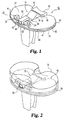
- the preferred embodiment of the present invention as incorporated in a knee joint includes a tibial base or tray 10 and a release member 12 slidably mounted on the intercondylar portion thereof on a smooth, flat superior surface 14.
- Release member 12 includes a wedge portion 16 and extends between the anterior edge 18 of base 10 and a retaining rail 20 extending superiorly from the posterior edge of the base.
- Tibial base 10 includes a pair of posts 22 and 24 integrally formed on the superior surface 14 of the base at the anterior edge thereof.
- the posts and rail are designed to cooperate to retain a modular bearing on the base, the modular bearing preferably being preformed of ultra-high molecular weight polyethylene (UHMWPE) with anterior and posterior recesses to receive the posts and rail, respectively, and with a uniformly flat inferior surface on its intercondylar and medial/lateral portions for direct contact with the superior surface 14 of the base.
- UHMWPE ultra-high molecular weight polyethylene
- the modular bearing is designed to be locked in position with a transverse slide-in locking bar or clip wedged between the posts and the bearing in opposed grooves provided therein for that purpose.
- Modular tibial trays and bearings as generally described above are commercially available from Biomet Inc., the assignee of the present invention, as components of the Maxim® Total Knee System, which includes various sizes and configurations of bases, bearings and stem extensions, as well as femoral and patellar components, for different patient requirements.
- a modular bearing is not implanted as the primary tibial bearing but instead is secured to the base during revision surgery after in vivo removal of a primary bearing which has preferably been molded over the base and the release member.
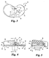
- a primary bearing 26 is shown in FIG. 2 as part of a complete nonmodular tibial component according to the preferred embodiment of this invention.
- UHMWPE is also a suitable material for the primary bearing, which is preferably molded by direct compression molding in a conventional manner.
- Release member 12 is preferably formed as a single piece with the thinner, anterior end 28 of wedge 16 integrally joined to an internally threaded drive block 30 and the thicker, posterior end 32 of the wedge integrally joined to a tail 34 which is sized and shaped to partially plug a transverse groove or channel 36 formed in the inwardly facing surface of rail 20.
- the wedge suitably has an anterior-posterior length of approximately 0.5", a width of approximately 0.5", and a height of approximately 0.25".
- the one-piece release member is suitably made of biocompatible titanium machined in a conventional manner, or may be cast cobalt-chromium. Its surfaces are preferably all smooth.
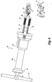
- the shape of the release member is shown in greater detail in FIGS. 3-6, from which it can be appreciated that the molded bearing conforms to the shape of the base and release member, filling all exposed spaces within the mold cavity, which is sized with respect to the base to provide a skirt 38 which covers the peripheral edge of the base and fills an elongated anterior edge groove 40, two medial/lateral edge grooves 42 and two posterior edge grooves 44 in the base as shown in the drawings.
- the skirt thus cooperates with other portions of the molded bearing, as will be described, to secure the bearing to the base.
- the skirt also tends to contain such debris.
- the thickness of the skirt adjacent to each such groove is suitably approximately .020-.030".
- the skirt thickness in that plane is correspondingly greater at the edge portions 41 and 43 of the base, where the edge of the base is cut away from its superior surface to the superior surface of a ledge 45 which partially defines the grooves.
- the inferior edge 46 of the skirt is trimmed after molding such that it is not flush with the interior surface 47 of the base, as will be explained, in order to minimize the chances of contact with bone cement during implantation.
- Each peripheral edge groove 44 extends from the posterior end of its respective edge portion 43 to within 0.1" of the adjacent edge of rail 20.
- the base has no groove in its posterior edge between the medial and lateral edges of rail 20, as perhaps best shown in FIG. 6.
- the threaded hole 48 in block 30 is a #12-24 hole and is plugged during the molding process by a set screw (not shown) which is later removed and which may, if desired, extend out of the hole virtually to the mold cavity wall to facilitate the creation of an access hole 50 for an extractor, as will be described, in the anterior surface of the bearing.
- a manual or automatic trimming step is contemplated to clear any residual polyethylene out of the desired hole 50, which is suitably circular but may be square or otherwise shaped.
- the threaded hole in block 30 may be left unplugged in the tibial component as implanted.
- Transverse groove 36 in rail 20 is partially plugged by tail 34 and partially exposed in the mold, as perhaps best illustrated in FIGS. 1 and 5, and it is filled with polyethylene during the molding process to the extent so exposed.
- Anterior grooves 52 and posterior grooves 54 in posts 22 and 24 are entirely exposed and are thus entirely filled with polyethylene in the preferred embodiment during the molding process.
- Incidental molding of polyethylene also occurs in the space between the release member and the superior surface of the base at the medial and lateral edges of the inferior surface of the release member, which edges are chamfered to match the radius of curvature of posts 22 and 24 as best illustrated in FIG. 4.
- the chamfered edges preferably extend the entire length of the release member.
- the inferior surface of the release member is otherwise smooth and flat.
- the medial and lateral edges of the superior surface of the wedge at its posterior end 32 may also be rounded if desired to maintain a particular bearing thickness at such points.
- An example set of groove dimensions suitable for this purpose is set forth below: Groove No.
- the tibial component with the bearing as shown in FIG. 2 is designed for cases in which the posterior cruciate ligament is retained.
- the same tibial base can accommodate bearings for cruciate-retaining applications and bearings for cruciate-substituting applications, where the tibial component is subjected to higher moments at the implant-bone interface.
- the bearing in a cruciate-substituting prosthesis includes a stabilizing post which projects superiorly from the articulating surface level. With the knee loaded in a flexed position, such a stabilizing post experiences an anteriorly directed force due to the absence of the posterior cruciate ligament.
- the force creates a moment about the transverse axis through the posts on the base that, if not counteracted, would cause the posterior edge of the bearing to lift off of the base.
- the base and posterior stabilized bearing must cooperate to withstand the load that is normally carried by the posterior cruciate ligament, and the tibial base as described above is so designed.
- the tibial component with the base and release member as described above has a molded bearing retention force, measured in terms of the maximum anteriorly directed force against a posterior stabilized bearing that the tibial component can sustain without dissociation, in excess of 400 lbs., which is well above the maximum expected in vivo load of 320 lbs.
- This retention force has been measured in a worse-case scenario in which the base is made in the minimum size presently available in the Maxim® product line (59 mm) and the bearing is molded to the base with the maximum rated polyethylene thickness presently available in the Maxim® product line (24 mm), with no compressive load.
- the test is performed by connecting a Maxim® femoral component to the tibial component at 90° flexion and then loading the femoral component axially to create an anterior force against the stabilizing post on the tibial bearing.
- the retention force would be greater with larger base sizes.
- the molded primary bearing is removed by actuation of the release member with the aid of an extractor 60 having a ball screw 62 enmeshed with a recirculating ball nut 64 that is nonrotatably mounted in a casing 66 having an axially extending prong 68 mounted on the distal end thereof on either side of the ball screw as a brace for the extractor.
- Each prong 68 has a pointed tip, one of which is partially cut away in FIG. 6 to reveal a portion of a threaded nose on a conical adapter, as will be described below.
- a suitable ball screw for such purposes is commercially available from Thomson Saginaw Ball Screw Company, Inc., Saginaw, Michigan, as Catalog No. 720426SS.
- a compatible ball nut is the Thomson Catalog No. 5708278 ball nut.
- a precision steel ball bushing bearing is mounted in the proximal end 70 of the casing to rotatably and slidably support an unthreaded proximal portion 72 of the ball screw shaft, and a T-handle 74 is mounted on that end of the ball screw shaft for rotation and consequent axial motion thereof.
- the tool preferably includes a releasable ratchet mechanism (not shown) to prevent clockwise rotation of the ball screw, thereby allowing the surgeon's grip on the T-handle to be temporarily released for repositioning during retraction of the ball screw.
- the ball screw shaft also has an unthreaded distal portion 76 on which is rotatably mounted an adapter 78 having an externally threaded nose 80 designed to engage the threaded drive block 30 of release member 12 in the tibial component.
- Access hole 50 in the bearing is formed with an inner diameter greater than the outer diameter of nose 80 for this purpose.
- the ball screw is advanced sufficiently to position the nose of the adapter axially beyond the prongs, and the nose of the adapter is then inserted through circular hole 50 in the anterior surface of the bearing and threaded into drive block 30 by manual rotation of the adapter.
- the ball screw is then retracted with the aid of the T-handle, without rotating the adapter.
- the prongs indent and thus firmly engage the anterior surface of the bearing as the ball screw is retracted, and, with the spacing between the bearing and ball nut fixed by the prongs, the release member is accordingly pulled anteriorly, whereupon the action of the wedge causes the bearing to move superiorly and disengage from the base.
- the primary bearing is raised to the point of disengagement and then removed with the release member as a unit, as shown in FIG. 6.
- the maximum translational force required to be exerted to remove a molded primary bearing from a 71 mm tray is approximately 670 pounds, which corresponds to a torque of approximately 30 inch-pounds applied to the handle end of the ball screw shaft. This amount of torque is well within the capability of a surgeon or surgical assistant of normal strength.
- the translational force exerted by the extractor is applied between the bearing and the release member, thereby avoiding any disturbance to the base.
- the bearing is removed substantially in one piece, although fragments of polyethylene may remain on the base, such as in posterior grooves 54 of posts 22 and 24. Any such fragments are easily removed, and the primary bearing is then replaced with a modular bearing and locking bar of the type described in the above-referenced Patent No. 5,330,534.
- the skirt on the molded primary bearing is trimmed after molding such that its inferior surface is not flush with the inferior surface 47 of the base, and, if desired, the skirt may be trimmed such that its inferior surface is flush with the superior surface of ledge 45.
- the primary bearing can be removed by actuation of the release member, as described above, without significant risk of unwanted resistance from bone cement or of any removal or disturbance of bone cement.
- the mold may be modified, if desired, to provide a correspondingly shorter skirt on the bearing.
- the modular bearing has no skirt and is no wider than the tibial base, and is therefore slightly smaller than the primary bearing, which extends slightly beyond the peripheral edge of the base as described above and as shown, e.g., in FIGS. 3 and 4.
- the modular bearing may be made as wide as the primary bearing it is designed to replace, such that it likewise extends slightly beyond the peripheral edge of the base, albeit without a skirt.
- the base may be machined from titanium with an integral stem but is preferably cast of cobalt-chromium. While a stem is a preferred part of the tibial component, the principles of the invention also apply to a stemless tibial base.
- FIGS. 7 and 8 A first alternative embodiment of a nonmodular tibial component according to the present invention is shown in FIGS. 7 and 8.
- a base 110 has an undercut portion 140 which is filled with polyethylene during the molding process and which cooperates with other molded bearing portions as in the preferred embodiment described above to secure the primary bearing on the tibial base.
- the undercut portion may extend around the entire periphery of the base or selected portions thereof.
- the construction of the tibial component, including release member 112, posterior rail 120, anterior posts 122 and 124, and molded primary bearing 126. is otherwise the same as that of the preferred embodiment described above. This embodiment may be useful in certain applications, such as in uncemented tibial implants where there is no possibility of contact with bone cement.
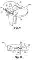
- FIG. 9 is a perspective view of a second alternative embodiment of a nonmodular tibial component according to the present invention.
- the release member 212 is provided with a pair of transverse arms 213 and 214 on the anterior end of the drive block 230.
- the posterior sides of the transverse arms fill the anterior grooves in posts 222 and 224 provided at the anterior edge of the base 210, and the anterior sides of the transverse arms are provided with respective cutting ridges 215 and 216 each of which extends the length of its arm, as shown in FIG. 9.
- the cutting ridges are provided to facilitate passage of the anterior end of the release member through the anterior portion of the primary bearing 226 and thereby facilitate forward motion of the release member.
- a scalpel may be used during revision surgery to cut into or through the relatively thin layer of polyethylene (approximately .010-.020”) covering the cutting ridge, if desired, to further facilitate the release action.
- tibial base 210 has a smooth, flat peripheral edge 218 rather than a grooved or undercut edge as in the previous embodiments.
- Base 210 and the rail 220 and posts 222 and 224 integrally formed thereon are otherwise the same as their counterparts in the preferred embodiment, as is release member 212. Due to the smooth, flat edge and the transverse arms, this embodiment provides less retention force than the previous embodiments, which may be suitable in some circumstances such as in cruciate-retaining applications. The retention force could be increased in this or either prior embodiment by forming the release member without a tail that extends into the channel in the rail.
- the anterior portion of the bearing already tends to disengage from the base well before the posterior portion. It is believed more desirable in most applications to have the anterior and posterior portions of the primary bearing disengage from the tibial base at approximately the same time, i.e., with negligible tilting, as in the preferred embodiment.
- the present invention also encompasses other forms of retainers and other methods of removing a molded primary bearing without removing the base.
- Other retainer forms presently contemplated as useful to varying degrees in certain applications include pegs, posts, holes or other recesses, dovetail configurations, tongue and groove configurations, mortise and tenon configurations, retaining walls, rails, detents, and snap ring grooves.
- the retainer may alternatively be in the form of a raised flange or rim about other portions or all of the periphery of the tibial base, with a cavity in an inwardly facing surface of the flange or rim, wherein the modular bearing has a corresponding tongue or lip on its outer edge surface that fits into the cavity, as in Patent No. 4,938,769 to Shaw or Patent No. 4,795,468 to Hodorek et al.
- the modular bearing may be secured to the base with the aid of an auxiliary locking element in the form of a spring clip that interlocks a groove in the rim wall and a corresponding groove in the outer edge surface of the bearing.
- the clip is mounted in one groove so as to protrude therefrom and snap into the other groove when the modular bearing is pressed against the base.
- the spring clip is preferably not incorporated in the primary tibial prosthesis, and the molded primary bearing preferably extends into the groove in the rim.
- the base may be provided with a threaded hole or holes designed to cooperate with a screw or screws to securely retain a modular bearing in place after the molded primary bearing has been removed during revision surgery.
- Such screws thereby serve as auxiliary mechanical locking elements.
- a base with an internally threaded stem designed to retain a modular bearing with the aid of a screw may be modified to have an undercut peripheral edge and then placed in a mold adapted to provide a polyethylene skirt which covers the peripheral edge and extends into the undercut portion sufficiently to secure the bearing to the base.
- the threaded stem hole is first plugged with a set screw or otherwise sealed to prevent entry of polyethylene, such as by covering the hole with a stopper of titanium or other suitable material to withstand the heat and pressure in the mold without deformation or fusing to the base.
- the molded primary bearing in the alternative embodiment just described is preferably removed in vivo by selectively cutting the skirt at the peripheral edge and then lifting the main portion of the bearing off of the base, using an osteotome if necessary or desired in conjunction with either a preformed slot or a slot that is cut or melted into the polyethylene at that time at the bearing-base interface to facilitate removal.
- a witness mark may be provided on the bearing edge surface at the time of molding to mark the level of the interface for such purposes.
- the set screw or stopper in the stem hole is removed after the primary bearing, and a modular bearing is then placed on the base and secured with a screw as described in the above-referenced Brown patent, which is hereby incorporated by reference along with the above-referenced patents to Shaw and Hodorek et al.
- the removal technique just described may be facilitated by the use of a C-clamp with an osteotome mounted on one end or jaw, with the C-clamp connected across the bearing, e.g., in contact with the medial and lateral edges of the bearing, with the tip of the osteotome inserted into a slot provided for that purpose or aligned with a witness mark.
- the opposing forces exerted by the C-clamp do not disturb the tibial base.
- This technique may also be used in lieu of a release member for removal of a bearing molded to any of the tibial bases of FIGS. 1, 7 or 9.
- a pin may be placed through a coaxial pair of through holes in a modular bearing and base and held in position by a clip as described in Patent No. 5,061,271 to Van Zile , which patent is hereby incorporated by reference.
- the tibial base may have one or more dovetail surface members such as disclosed in the above-referenced Van Zile or Shaw patents.
- the retainer may alternatively be designed to allow a modular bearing to float to some degree, either by translation or rotation.
- a modular bearing may be rotatably mounted on a tibial base and retained thereon by means of an unthreaded hole in the surface of the base in cooperation with a mating stem on the inferior surface of the bearing.
- Peripheral edge grooves may be provided on the base and filled with polyethylene, as described above with reference to FIG. 1, in order to secure a nonmodular bearing to the base. Similar transversely oriented grooves may be provided at a desired depth within the hole in the base if desired.
- the nonmodular tibial prosthesis preferably includes a centrally mounted release member having a wedge and drive block similar to that shown in FIG. 1, with the wedge portion wider than the hole in the base.
- release members including one-piece and multi-piece mechanisms.
- two wedges with complementary inclined surfaces could be provided with a counterdrive mechanism to force the wedges toward or away from each other, depending on their orientation, so as to jointly raise the bearing off of the superior surface of the base.
- the molded primary bearing is adapted to be pulled directly away from the superior surface of the base with the aid of a release member in the form of a simple plate, e.g., a relatively thin disc, located between the bearing and base.
- a modified form of the extractor shown in FIG. 6 is adapted to engage the plate through an access hole provided in the superior surface of the bearing as molded.
- the plate has a threaded hole with its axis perpendicular to the superior surface of the base, and is mounted in the intercondylar area of the base in place of the release member shown in FIG. 1.
- a # 12-24 hole is suitable as in the preferred embodiment.
- a through hole coaxial with the hole in the plate is provided in the superior surface of the bearing as an access hole for a threaded nose of an extractor as shown in FIG. 6 but modified to have a longer nose for this purpose.
- the extractor is adapted to be aligned with the access hole axis with a fixed spacing between the extractor casing and the tibial base. This spacing may be maintained with prongs as shown in FIG. 6 but spaced further apart so as to straddle the bearing and engage contact points provided on the base for this purpose.
- the contact points may, for example, be peripheral extensions of ledge 45 on the base of FIG. 1 which are not covered with polyethylene during the molding process. If the prongs have pointed tips as in the embodiment of FIG. 6. each contact point on the base preferably has an indentation in its superior surface to receive a prong tip and fix its position in the transverse plane.
- the base is otherwise the same as shown in FIG. 1.
- the extractor In operation, the extractor is positioned with the prongs on the contact points on the base and the extended nose of the extractor threaded into the plate. The ball screw of the extractor is then retracted, whereby the plate exerts a superiorly directed force against the bearing and thus raises it off of the base surface.
- the shear area of the portion of the molded bearing above the plate is greater than the total shear area of the portions of the molded bearing in the grooves in the posts, rail and peripheral edges of the base.
- the extractor may be provided with a pair of jaws with opposed sharp edges adapted to cut into the peripheral skirt on the bearing and engage the medial/lateral edge grooves 42 in the tibial base, whereby the extractor may be clamped to the base.
- the primary bearing With the nose of the extracter threaded into the plate, the primary bearing may be pulled directly away from the superior surface of the base along with the release plate upon retraction of the ball screw in the extractor.
- the primary bearing may be removed in vivo by sectioning, reaming or grinding the bearing or key points thereof.
- an acetabular cup having a porous shell may be provided with an annular groove for retention of a preformed bearing insert as a modular revision bearing, and the primary bearing may be formed in the porous shell by direct compression molding of polyethylene which is later reamed out during revision surgery sufficiently to allow insertion ot the preformed insert.
- the shell may be either a metal shell with a porous coating or an uncoated shell made of a porous material having structural integrity such as porous tantalum.
- a bearing of the type shown in FIG. 2 but molded to the base 10 without a release member thereon may alternatively be removed by sectioning.
- a mediallateral strip 1/4" to 1/2" wide may be cut out of the bearing with a saw or mill, and the remaining anterior and posterior bearing portions may then be forced toward each other, and thereby disengaged from the posts, the rail and the edge grooves on the base, with the aid of pliers or a clamp adapted with prongs or otherwise to pierce or otherwise firmly engage the anterior and posterior bearing surfaces.
- Reamers, saws and osteotomes may disturb a prosthesis or damage it, e.g., by scratching the smooth superior surface of a tibial base. Therefore, while methods involving such tools are options for revision procedures, it is preferred to incorporate a release member in the nonmodular prosthesis which allows a bearing to be removed without the application of force to the base member.
- the nonmodular bearing may be secured in ways other than by molding in certain applications.
- an interference fit may be provided between a preformed bearing and a mating base with the aid of a press in the factory.
- Thermally aided assembly is another alternative.
- a barbed central post on the base may be heated so as to locally melt the polyethylene in a preformed bearing as the bearing is pressed onto it; upon cooling, the polyethylene is secured to the post and thereby to the base, which may be provided with ancillary retaining elements such as a retaining rim.
- a nonmodular prosthesis may also be fabricated using a permanent adhesive to secure a preformed bearing to a base. Such methods are considered possible although not preferred.
- a recess must be provided in the bearing's inferior surface for a release member if one is desired for the intended application.
Landscapes
- Health & Medical Sciences (AREA)
- Orthopedic Medicine & Surgery (AREA)
- Transplantation (AREA)
- Heart & Thoracic Surgery (AREA)
- Life Sciences & Earth Sciences (AREA)
- Cardiology (AREA)
- Engineering & Computer Science (AREA)
- Biomedical Technology (AREA)
- Physical Education & Sports Medicine (AREA)
- Vascular Medicine (AREA)
- Oral & Maxillofacial Surgery (AREA)
- Animal Behavior & Ethology (AREA)
- General Health & Medical Sciences (AREA)
- Public Health (AREA)
- Veterinary Medicine (AREA)
- Prostheses (AREA)
- External Artificial Organs (AREA)
Applications Claiming Priority (5)
| Application Number | Priority Date | Filing Date | Title |
|---|---|---|---|
| US17394098A | 1998-10-16 | 1998-10-16 | |
| US17421598A | 1998-10-16 | 1998-10-16 | |
| US174215 | 1998-10-16 | ||
| US173940 | 1998-10-16 | ||
| PCT/US1999/024235 WO2000023012A1 (en) | 1998-10-16 | 1999-10-14 | Nonmodular joint prosthesis convertible in vivo to a modular prosthesis |
Publications (3)
| Publication Number | Publication Date |
|---|---|
| EP1091705A1 EP1091705A1 (en) | 2001-04-18 |
| EP1091705A4 EP1091705A4 (en) | 2004-09-08 |
| EP1091705B1 true EP1091705B1 (en) | 2007-08-15 |
Family
ID=26869706
Family Applications (1)
| Application Number | Title | Priority Date | Filing Date |
|---|---|---|---|
| EP99954977A Expired - Lifetime EP1091705B1 (en) | 1998-10-16 | 1999-10-14 | Nonmodular joint prosthesis convertible in vivo to a modular prosthesis |
Country Status (6)
| Country | Link |
|---|---|
| EP (1) | EP1091705B1 (enExample) |
| JP (1) | JP4242074B2 (enExample) |
| AT (1) | ATE369814T1 (enExample) |
| AU (1) | AU1119200A (enExample) |
| DE (1) | DE69936862D1 (enExample) |
| WO (1) | WO2000023012A1 (enExample) |
Cited By (4)
| Publication number | Priority date | Publication date | Assignee | Title |
|---|---|---|---|---|
| US11291549B2 (en) | 2019-12-11 | 2022-04-05 | Depuy Ireland Unlimited Company | Ceramic acetabular shell liners with augments |
| US11376128B2 (en) | 2018-12-31 | 2022-07-05 | Depuy Ireland Unlimited Company | Acetabular orthopaedic prosthesis and method |
| US11628066B2 (en) | 2019-12-11 | 2023-04-18 | Depuy Ireland Unlimited Company | Ceramic acetabular shell liner with a metal ring having a lead-in surface |
| US12171666B2 (en) | 2019-12-10 | 2024-12-24 | Depuy Ireland Unlimited Company | Metal reinforced acetabular shell liner |
Families Citing this family (13)
| Publication number | Priority date | Publication date | Assignee | Title |
|---|---|---|---|---|
| US7207993B1 (en) | 2000-02-03 | 2007-04-24 | Pioneer Laboratories, Inc. | Apparatus and method for repairing the femur |
| US10231839B2 (en) | 2000-07-18 | 2019-03-19 | Encore Medical, L.P. | Elbow prosthesis |
| AU2001276931A1 (en) | 2000-07-18 | 2002-01-30 | Biomet, Inc. | Elbow prosthesis |
| US9561110B2 (en) | 2000-07-18 | 2017-02-07 | Encore Medical, L.P. | Elbow prosthesis |
| US8932362B2 (en) * | 2000-07-18 | 2015-01-13 | Biomet Manufacturing, Llc | Elbow prosthesis |
| US8998995B2 (en) | 2000-07-18 | 2015-04-07 | Biomet Manufacturing, Llc | Elbow prosthesis |
| US6488713B1 (en) | 2001-04-25 | 2002-12-03 | Biomet, Inc. | Hip joint prosthesis with integral bearing extraction member |
| US7766969B2 (en) | 2005-12-05 | 2010-08-03 | Zimmer, Inc. | Modular progressive implant for a joint articulation surface |
| US9034050B2 (en) | 2009-09-18 | 2015-05-19 | Biomet Manufacturing, Llc | Elbow prosthesis |
| US11213400B2 (en) | 2012-05-07 | 2022-01-04 | Encore Medical, L.P. | Elbow prosthesis |
| US9861491B2 (en) * | 2014-04-30 | 2018-01-09 | Depuy Ireland Unlimited Company | Tibial trial system for a knee prosthesis |
| KR101954936B1 (ko) * | 2017-03-23 | 2019-03-11 | 주식회사 코렌텍 | 탈부착 가능한 무릎 트라이얼 |
| US20240252221A1 (en) * | 2023-01-31 | 2024-08-01 | Shukla Medical | Surgical extractor with a ratcheting handle device |
Family Cites Families (7)
| Publication number | Priority date | Publication date | Assignee | Title |
|---|---|---|---|---|
| US4479271A (en) * | 1981-10-26 | 1984-10-30 | Zimmer, Inc. | Prosthetic device adapted to promote bone/tissue ingrowth |
| US4795468A (en) * | 1987-12-23 | 1989-01-03 | Zimmer, Inc. | Mechanism and method for locking a bearing insert to the base of a prosthetic implant |
| US4936853A (en) * | 1989-01-11 | 1990-06-26 | Kirschner Medical Corporation | Modular knee prosthesis |
| US5330534A (en) * | 1992-02-10 | 1994-07-19 | Biomet, Inc. | Knee joint prosthesis with interchangeable components |
| FR2702651B1 (fr) * | 1993-03-16 | 1995-04-28 | Erato | Prothèse du genou. |
| ATE226053T1 (de) * | 1996-05-28 | 2002-11-15 | Howmedica Internat S De R L | Tibiateil für eine knieprothese |
| US5824103A (en) * | 1997-05-12 | 1998-10-20 | Howmedica Inc. | Tibial prosthesis |
-
1999
- 1999-10-14 WO PCT/US1999/024235 patent/WO2000023012A1/en not_active Ceased
- 1999-10-14 JP JP2000576790A patent/JP4242074B2/ja not_active Expired - Fee Related
- 1999-10-14 DE DE69936862T patent/DE69936862D1/de not_active Expired - Lifetime
- 1999-10-14 AU AU11192/00A patent/AU1119200A/en not_active Abandoned
- 1999-10-14 EP EP99954977A patent/EP1091705B1/en not_active Expired - Lifetime
- 1999-10-14 AT AT99954977T patent/ATE369814T1/de not_active IP Right Cessation
Cited By (5)
| Publication number | Priority date | Publication date | Assignee | Title |
|---|---|---|---|---|
| US11376128B2 (en) | 2018-12-31 | 2022-07-05 | Depuy Ireland Unlimited Company | Acetabular orthopaedic prosthesis and method |
| US12171666B2 (en) | 2019-12-10 | 2024-12-24 | Depuy Ireland Unlimited Company | Metal reinforced acetabular shell liner |
| US11291549B2 (en) | 2019-12-11 | 2022-04-05 | Depuy Ireland Unlimited Company | Ceramic acetabular shell liners with augments |
| US11628066B2 (en) | 2019-12-11 | 2023-04-18 | Depuy Ireland Unlimited Company | Ceramic acetabular shell liner with a metal ring having a lead-in surface |
| US12274623B2 (en) | 2019-12-11 | 2025-04-15 | Depuy Ireland Unlimited Company | Ceramic acetabular shell liners with augments |
Also Published As
| Publication number | Publication date |
|---|---|
| EP1091705A4 (en) | 2004-09-08 |
| ATE369814T1 (de) | 2007-09-15 |
| JP2002527194A (ja) | 2002-08-27 |
| EP1091705A1 (en) | 2001-04-18 |
| DE69936862D1 (de) | 2007-09-27 |
| AU1119200A (en) | 2000-05-08 |
| WO2000023012A1 (en) | 2000-04-27 |
| JP4242074B2 (ja) | 2009-03-18 |
Similar Documents
| Publication | Publication Date | Title |
|---|---|---|
| US6280476B1 (en) | Hip joint prosthesis convertible in vivo to a modular prosthesis | |
| US6500208B1 (en) | Nonmodular joint prosthesis convertible in vivo to a modular prosthesis | |
| EP1091705B1 (en) | Nonmodular joint prosthesis convertible in vivo to a modular prosthesis | |
| US6488713B1 (en) | Hip joint prosthesis with integral bearing extraction member | |
| EP2008617B1 (en) | Modular progressive implant for a joint articulation surface | |
| US10085841B2 (en) | Femoral implant systems | |
| EP0358732B1 (en) | Modular prosthetic joint and extraction tools | |
| US9579208B2 (en) | Modular radial head prosthesis | |
| US6139581A (en) | Posterior compensation tibial tray | |
| EP3400911B1 (en) | Tibial tray with fixation features | |
| JP6242608B2 (ja) | 人工脛骨を分解する外科用器具及び方法 | |
| AU7490291A (en) | Recessed patellar prosthesis | |
| EP2777624B1 (en) | Orthopaedic prosthesis | |
| US20220142787A1 (en) | Augmented Glenoid Design | |
| ES2406154T3 (es) | Prótesis con extensiones modulares | |
| US5490853A (en) | Orthopedic bone plug cutter | |
| CA1330688C (en) | Modular joint prosthesis |
Legal Events
| Date | Code | Title | Description |
|---|---|---|---|
| PUAI | Public reference made under article 153(3) epc to a published international application that has entered the european phase |
Free format text: ORIGINAL CODE: 0009012 |
|
| 17P | Request for examination filed |
Effective date: 20010109 |
|
| AK | Designated contracting states |
Kind code of ref document: A1 Designated state(s): AT BE CH CY DE DK ES FI FR GB GR IE IT LI LU MC NL PT SE |
|
| RIN1 | Information on inventor provided before grant (corrected) |
Inventor name: HERSHBERGER, TROY W. Inventor name: ASNIS, STANLEY, E. Inventor name: METZGER, ROBERT, G. |
|
| A4 | Supplementary search report drawn up and despatched |
Effective date: 20040716 |
|
| GRAP | Despatch of communication of intention to grant a patent |
Free format text: ORIGINAL CODE: EPIDOSNIGR1 |
|
| GRAS | Grant fee paid |
Free format text: ORIGINAL CODE: EPIDOSNIGR3 |
|
| GRAA | (expected) grant |
Free format text: ORIGINAL CODE: 0009210 |
|
| RIN1 | Information on inventor provided before grant (corrected) |
Inventor name: ASNIS, STANLEY, E. Inventor name: METZGER, ROBERT, G. |
|
| AK | Designated contracting states |
Kind code of ref document: B1 Designated state(s): AT BE CH CY DE DK ES FI FR GB GR IE IT LI LU MC NL PT SE |
|
| REG | Reference to a national code |
Ref country code: GB Ref legal event code: FG4D |
|
| REG | Reference to a national code |
Ref country code: CH Ref legal event code: EP |
|
| REG | Reference to a national code |
Ref country code: IE Ref legal event code: FG4D |
|
| REF | Corresponds to: |
Ref document number: 69936862 Country of ref document: DE Date of ref document: 20070927 Kind code of ref document: P |
|
| PG25 | Lapsed in a contracting state [announced via postgrant information from national office to epo] |
Ref country code: NL Free format text: LAPSE BECAUSE OF FAILURE TO SUBMIT A TRANSLATION OF THE DESCRIPTION OR TO PAY THE FEE WITHIN THE PRESCRIBED TIME-LIMIT Effective date: 20070815 Ref country code: FI Free format text: LAPSE BECAUSE OF FAILURE TO SUBMIT A TRANSLATION OF THE DESCRIPTION OR TO PAY THE FEE WITHIN THE PRESCRIBED TIME-LIMIT Effective date: 20070815 Ref country code: ES Free format text: LAPSE BECAUSE OF FAILURE TO SUBMIT A TRANSLATION OF THE DESCRIPTION OR TO PAY THE FEE WITHIN THE PRESCRIBED TIME-LIMIT Effective date: 20071126 |
|
| NLV1 | Nl: lapsed or annulled due to failure to fulfill the requirements of art. 29p and 29m of the patents act | ||
| PG25 | Lapsed in a contracting state [announced via postgrant information from national office to epo] |
Ref country code: CH Free format text: LAPSE BECAUSE OF FAILURE TO SUBMIT A TRANSLATION OF THE DESCRIPTION OR TO PAY THE FEE WITHIN THE PRESCRIBED TIME-LIMIT Effective date: 20070815 Ref country code: AT Free format text: LAPSE BECAUSE OF FAILURE TO SUBMIT A TRANSLATION OF THE DESCRIPTION OR TO PAY THE FEE WITHIN THE PRESCRIBED TIME-LIMIT Effective date: 20070815 Ref country code: LI Free format text: LAPSE BECAUSE OF FAILURE TO SUBMIT A TRANSLATION OF THE DESCRIPTION OR TO PAY THE FEE WITHIN THE PRESCRIBED TIME-LIMIT Effective date: 20070815 |
|
| REG | Reference to a national code |
Ref country code: CH Ref legal event code: PL |
|
| PG25 | Lapsed in a contracting state [announced via postgrant information from national office to epo] |
Ref country code: BE Free format text: LAPSE BECAUSE OF FAILURE TO SUBMIT A TRANSLATION OF THE DESCRIPTION OR TO PAY THE FEE WITHIN THE PRESCRIBED TIME-LIMIT Effective date: 20070815 |
|
| EN | Fr: translation not filed | ||
| PG25 | Lapsed in a contracting state [announced via postgrant information from national office to epo] |
Ref country code: GR Free format text: LAPSE BECAUSE OF FAILURE TO SUBMIT A TRANSLATION OF THE DESCRIPTION OR TO PAY THE FEE WITHIN THE PRESCRIBED TIME-LIMIT Effective date: 20071116 Ref country code: DK Free format text: LAPSE BECAUSE OF FAILURE TO SUBMIT A TRANSLATION OF THE DESCRIPTION OR TO PAY THE FEE WITHIN THE PRESCRIBED TIME-LIMIT Effective date: 20070815 Ref country code: DE Free format text: LAPSE BECAUSE OF FAILURE TO SUBMIT A TRANSLATION OF THE DESCRIPTION OR TO PAY THE FEE WITHIN THE PRESCRIBED TIME-LIMIT Effective date: 20071119 |
|
| PG25 | Lapsed in a contracting state [announced via postgrant information from national office to epo] |
Ref country code: PT Free format text: LAPSE BECAUSE OF FAILURE TO SUBMIT A TRANSLATION OF THE DESCRIPTION OR TO PAY THE FEE WITHIN THE PRESCRIBED TIME-LIMIT Effective date: 20080115 Ref country code: MC Free format text: LAPSE BECAUSE OF NON-PAYMENT OF DUE FEES Effective date: 20071031 |
|
| PLBE | No opposition filed within time limit |
Free format text: ORIGINAL CODE: 0009261 |
|
| STAA | Information on the status of an ep patent application or granted ep patent |
Free format text: STATUS: NO OPPOSITION FILED WITHIN TIME LIMIT |
|
| PG25 | Lapsed in a contracting state [announced via postgrant information from national office to epo] |
Ref country code: SE Free format text: LAPSE BECAUSE OF FAILURE TO SUBMIT A TRANSLATION OF THE DESCRIPTION OR TO PAY THE FEE WITHIN THE PRESCRIBED TIME-LIMIT Effective date: 20071115 |
|
| 26N | No opposition filed |
Effective date: 20080516 |
|
| PG25 | Lapsed in a contracting state [announced via postgrant information from national office to epo] |
Ref country code: IE Free format text: LAPSE BECAUSE OF NON-PAYMENT OF DUE FEES Effective date: 20071015 |
|
| PG25 | Lapsed in a contracting state [announced via postgrant information from national office to epo] |
Ref country code: FR Free format text: LAPSE BECAUSE OF NON-PAYMENT OF DUE FEES Effective date: 20071031 |
|
| PG25 | Lapsed in a contracting state [announced via postgrant information from national office to epo] |
Ref country code: CY Free format text: LAPSE BECAUSE OF FAILURE TO SUBMIT A TRANSLATION OF THE DESCRIPTION OR TO PAY THE FEE WITHIN THE PRESCRIBED TIME-LIMIT Effective date: 20070815 |
|
| PG25 | Lapsed in a contracting state [announced via postgrant information from national office to epo] |
Ref country code: LU Free format text: LAPSE BECAUSE OF NON-PAYMENT OF DUE FEES Effective date: 20071014 |
|
| PG25 | Lapsed in a contracting state [announced via postgrant information from national office to epo] |
Ref country code: IT Free format text: LAPSE BECAUSE OF NON-PAYMENT OF DUE FEES Effective date: 20071031 |
|
| PGFP | Annual fee paid to national office [announced via postgrant information from national office to epo] |
Ref country code: GB Payment date: 20181228 Year of fee payment: 20 |
|
| REG | Reference to a national code |
Ref country code: GB Ref legal event code: PE20 Expiry date: 20191013 |
|
| PG25 | Lapsed in a contracting state [announced via postgrant information from national office to epo] |
Ref country code: GB Free format text: LAPSE BECAUSE OF EXPIRATION OF PROTECTION Effective date: 20191013 |