EP3400911B1 - Tibial tray with fixation features - Google Patents
Tibial tray with fixation features Download PDFInfo
- Publication number
- EP3400911B1 EP3400911B1 EP18171207.6A EP18171207A EP3400911B1 EP 3400911 B1 EP3400911 B1 EP 3400911B1 EP 18171207 A EP18171207 A EP 18171207A EP 3400911 B1 EP3400911 B1 EP 3400911B1
- Authority
- EP
- European Patent Office
- Prior art keywords
- distal
- wall
- posterior
- opening
- Prior art date
- Legal status (The legal status is an assumption and is not a legal conclusion. Google has not performed a legal analysis and makes no representation as to the accuracy of the status listed.)
- Active
Links
- 230000003746 surface roughness Effects 0.000 claims description 13
- 230000002093 peripheral effect Effects 0.000 claims description 9
- 239000002639 bone cement Substances 0.000 description 12
- 239000004568 cement Substances 0.000 description 8
- 210000002303 tibia Anatomy 0.000 description 8
- 210000000988 bone and bone Anatomy 0.000 description 6
- 239000007943 implant Substances 0.000 description 6
- 238000002513 implantation Methods 0.000 description 6
- 230000008901 benefit Effects 0.000 description 4
- 210000003127 knee Anatomy 0.000 description 4
- 239000000463 material Substances 0.000 description 4
- 238000000034 method Methods 0.000 description 4
- 210000000689 upper leg Anatomy 0.000 description 4
- 150000002632 lipids Chemical class 0.000 description 3
- 238000004519 manufacturing process Methods 0.000 description 3
- 238000012986 modification Methods 0.000 description 3
- 230000004048 modification Effects 0.000 description 3
- 238000001356 surgical procedure Methods 0.000 description 3
- 210000003484 anatomy Anatomy 0.000 description 2
- 230000003247 decreasing effect Effects 0.000 description 2
- 230000008595 infiltration Effects 0.000 description 2
- 238000001764 infiltration Methods 0.000 description 2
- 238000013150 knee replacement Methods 0.000 description 2
- 229910000684 Cobalt-chrome Inorganic materials 0.000 description 1
- 239000004698 Polyethylene Substances 0.000 description 1
- 229920010741 Ultra High Molecular Weight Polyethylene (UHMWPE) Polymers 0.000 description 1
- 229910045601 alloy Inorganic materials 0.000 description 1
- 239000000956 alloy Substances 0.000 description 1
- 210000004027 cell Anatomy 0.000 description 1
- 239000010952 cobalt-chrome Substances 0.000 description 1
- 201000010099 disease Diseases 0.000 description 1
- 208000037265 diseases, disorders, signs and symptoms Diseases 0.000 description 1
- 208000014674 injury Diseases 0.000 description 1
- 230000003993 interaction Effects 0.000 description 1
- 230000013011 mating Effects 0.000 description 1
- 238000005259 measurement Methods 0.000 description 1
- 239000002184 metal Substances 0.000 description 1
- 229910052751 metal Inorganic materials 0.000 description 1
- -1 polyethylene Polymers 0.000 description 1
- 229920000573 polyethylene Polymers 0.000 description 1
- 239000011253 protective coating Substances 0.000 description 1
- 230000009467 reduction Effects 0.000 description 1
- 238000004381 surface treatment Methods 0.000 description 1
- 210000001519 tissue Anatomy 0.000 description 1
- 230000008733 trauma Effects 0.000 description 1
Images


Classifications
-
- A—HUMAN NECESSITIES
- A61—MEDICAL OR VETERINARY SCIENCE; HYGIENE
- A61F—FILTERS IMPLANTABLE INTO BLOOD VESSELS; PROSTHESES; DEVICES PROVIDING PATENCY TO, OR PREVENTING COLLAPSING OF, TUBULAR STRUCTURES OF THE BODY, e.g. STENTS; ORTHOPAEDIC, NURSING OR CONTRACEPTIVE DEVICES; FOMENTATION; TREATMENT OR PROTECTION OF EYES OR EARS; BANDAGES, DRESSINGS OR ABSORBENT PADS; FIRST-AID KITS
- A61F2/00—Filters implantable into blood vessels; Prostheses, i.e. artificial substitutes or replacements for parts of the body; Appliances for connecting them with the body; Devices providing patency to, or preventing collapsing of, tubular structures of the body, e.g. stents
- A61F2/02—Prostheses implantable into the body
- A61F2/30—Joints
- A61F2/38—Joints for elbows or knees
- A61F2/389—Tibial components
-
- A—HUMAN NECESSITIES
- A61—MEDICAL OR VETERINARY SCIENCE; HYGIENE
- A61B—DIAGNOSIS; SURGERY; IDENTIFICATION
- A61B17/00—Surgical instruments, devices or methods, e.g. tourniquets
- A61B17/56—Surgical instruments or methods for treatment of bones or joints; Devices specially adapted therefor
- A61B17/58—Surgical instruments or methods for treatment of bones or joints; Devices specially adapted therefor for osteosynthesis, e.g. bone plates, screws, setting implements or the like
- A61B17/88—Osteosynthesis instruments; Methods or means for implanting or extracting internal or external fixation devices
- A61B17/8802—Equipment for handling bone cement or other fluid fillers
-
- A—HUMAN NECESSITIES
- A61—MEDICAL OR VETERINARY SCIENCE; HYGIENE
- A61F—FILTERS IMPLANTABLE INTO BLOOD VESSELS; PROSTHESES; DEVICES PROVIDING PATENCY TO, OR PREVENTING COLLAPSING OF, TUBULAR STRUCTURES OF THE BODY, e.g. STENTS; ORTHOPAEDIC, NURSING OR CONTRACEPTIVE DEVICES; FOMENTATION; TREATMENT OR PROTECTION OF EYES OR EARS; BANDAGES, DRESSINGS OR ABSORBENT PADS; FIRST-AID KITS
- A61F2/00—Filters implantable into blood vessels; Prostheses, i.e. artificial substitutes or replacements for parts of the body; Appliances for connecting them with the body; Devices providing patency to, or preventing collapsing of, tubular structures of the body, e.g. stents
- A61F2/02—Prostheses implantable into the body
- A61F2/30—Joints
- A61F2/30767—Special external or bone-contacting surface, e.g. coating for improving bone ingrowth
-
- A—HUMAN NECESSITIES
- A61—MEDICAL OR VETERINARY SCIENCE; HYGIENE
- A61F—FILTERS IMPLANTABLE INTO BLOOD VESSELS; PROSTHESES; DEVICES PROVIDING PATENCY TO, OR PREVENTING COLLAPSING OF, TUBULAR STRUCTURES OF THE BODY, e.g. STENTS; ORTHOPAEDIC, NURSING OR CONTRACEPTIVE DEVICES; FOMENTATION; TREATMENT OR PROTECTION OF EYES OR EARS; BANDAGES, DRESSINGS OR ABSORBENT PADS; FIRST-AID KITS
- A61F2/00—Filters implantable into blood vessels; Prostheses, i.e. artificial substitutes or replacements for parts of the body; Appliances for connecting them with the body; Devices providing patency to, or preventing collapsing of, tubular structures of the body, e.g. stents
- A61F2/02—Prostheses implantable into the body
- A61F2/30—Joints
- A61F2002/30001—Additional features of subject-matter classified in A61F2/28, A61F2/30 and subgroups thereof
- A61F2002/30316—The prosthesis having different structural features at different locations within the same prosthesis; Connections between prosthetic parts; Special structural features of bone or joint prostheses not otherwise provided for
- A61F2002/30317—The prosthesis having different structural features at different locations within the same prosthesis
- A61F2002/30321—The prosthesis having different structural features at different locations within the same prosthesis differing in roughness
-
- A—HUMAN NECESSITIES
- A61—MEDICAL OR VETERINARY SCIENCE; HYGIENE
- A61F—FILTERS IMPLANTABLE INTO BLOOD VESSELS; PROSTHESES; DEVICES PROVIDING PATENCY TO, OR PREVENTING COLLAPSING OF, TUBULAR STRUCTURES OF THE BODY, e.g. STENTS; ORTHOPAEDIC, NURSING OR CONTRACEPTIVE DEVICES; FOMENTATION; TREATMENT OR PROTECTION OF EYES OR EARS; BANDAGES, DRESSINGS OR ABSORBENT PADS; FIRST-AID KITS
- A61F2/00—Filters implantable into blood vessels; Prostheses, i.e. artificial substitutes or replacements for parts of the body; Appliances for connecting them with the body; Devices providing patency to, or preventing collapsing of, tubular structures of the body, e.g. stents
- A61F2/02—Prostheses implantable into the body
- A61F2/30—Joints
- A61F2/30721—Accessories
- A61F2002/30733—Inserts placed into an endoprosthetic cavity, e.g. for modifying a material property
-
- A—HUMAN NECESSITIES
- A61—MEDICAL OR VETERINARY SCIENCE; HYGIENE
- A61F—FILTERS IMPLANTABLE INTO BLOOD VESSELS; PROSTHESES; DEVICES PROVIDING PATENCY TO, OR PREVENTING COLLAPSING OF, TUBULAR STRUCTURES OF THE BODY, e.g. STENTS; ORTHOPAEDIC, NURSING OR CONTRACEPTIVE DEVICES; FOMENTATION; TREATMENT OR PROTECTION OF EYES OR EARS; BANDAGES, DRESSINGS OR ABSORBENT PADS; FIRST-AID KITS
- A61F2/00—Filters implantable into blood vessels; Prostheses, i.e. artificial substitutes or replacements for parts of the body; Appliances for connecting them with the body; Devices providing patency to, or preventing collapsing of, tubular structures of the body, e.g. stents
- A61F2/02—Prostheses implantable into the body
- A61F2/30—Joints
- A61F2/30767—Special external or bone-contacting surface, e.g. coating for improving bone ingrowth
- A61F2/30771—Special external or bone-contacting surface, e.g. coating for improving bone ingrowth applied in original prostheses, e.g. holes or grooves
- A61F2002/30795—Blind bores, e.g. of circular cross-section
- A61F2002/308—Blind bores, e.g. of circular cross-section oblong
-
- A—HUMAN NECESSITIES
- A61—MEDICAL OR VETERINARY SCIENCE; HYGIENE
- A61F—FILTERS IMPLANTABLE INTO BLOOD VESSELS; PROSTHESES; DEVICES PROVIDING PATENCY TO, OR PREVENTING COLLAPSING OF, TUBULAR STRUCTURES OF THE BODY, e.g. STENTS; ORTHOPAEDIC, NURSING OR CONTRACEPTIVE DEVICES; FOMENTATION; TREATMENT OR PROTECTION OF EYES OR EARS; BANDAGES, DRESSINGS OR ABSORBENT PADS; FIRST-AID KITS
- A61F2/00—Filters implantable into blood vessels; Prostheses, i.e. artificial substitutes or replacements for parts of the body; Appliances for connecting them with the body; Devices providing patency to, or preventing collapsing of, tubular structures of the body, e.g. stents
- A61F2/02—Prostheses implantable into the body
- A61F2/30—Joints
- A61F2/30767—Special external or bone-contacting surface, e.g. coating for improving bone ingrowth
- A61F2/30771—Special external or bone-contacting surface, e.g. coating for improving bone ingrowth applied in original prostheses, e.g. holes or grooves
- A61F2002/30795—Blind bores, e.g. of circular cross-section
- A61F2002/30805—Recesses of comparatively large area with respect to their low depth
-
- A—HUMAN NECESSITIES
- A61—MEDICAL OR VETERINARY SCIENCE; HYGIENE
- A61F—FILTERS IMPLANTABLE INTO BLOOD VESSELS; PROSTHESES; DEVICES PROVIDING PATENCY TO, OR PREVENTING COLLAPSING OF, TUBULAR STRUCTURES OF THE BODY, e.g. STENTS; ORTHOPAEDIC, NURSING OR CONTRACEPTIVE DEVICES; FOMENTATION; TREATMENT OR PROTECTION OF EYES OR EARS; BANDAGES, DRESSINGS OR ABSORBENT PADS; FIRST-AID KITS
- A61F2/00—Filters implantable into blood vessels; Prostheses, i.e. artificial substitutes or replacements for parts of the body; Appliances for connecting them with the body; Devices providing patency to, or preventing collapsing of, tubular structures of the body, e.g. stents
- A61F2/02—Prostheses implantable into the body
- A61F2/30—Joints
- A61F2/30767—Special external or bone-contacting surface, e.g. coating for improving bone ingrowth
- A61F2/30771—Special external or bone-contacting surface, e.g. coating for improving bone ingrowth applied in original prostheses, e.g. holes or grooves
- A61F2002/30795—Blind bores, e.g. of circular cross-section
- A61F2002/30807—Plurality of blind bores
- A61F2002/30808—Plurality of blind bores parallel
-
- A—HUMAN NECESSITIES
- A61—MEDICAL OR VETERINARY SCIENCE; HYGIENE
- A61F—FILTERS IMPLANTABLE INTO BLOOD VESSELS; PROSTHESES; DEVICES PROVIDING PATENCY TO, OR PREVENTING COLLAPSING OF, TUBULAR STRUCTURES OF THE BODY, e.g. STENTS; ORTHOPAEDIC, NURSING OR CONTRACEPTIVE DEVICES; FOMENTATION; TREATMENT OR PROTECTION OF EYES OR EARS; BANDAGES, DRESSINGS OR ABSORBENT PADS; FIRST-AID KITS
- A61F2/00—Filters implantable into blood vessels; Prostheses, i.e. artificial substitutes or replacements for parts of the body; Appliances for connecting them with the body; Devices providing patency to, or preventing collapsing of, tubular structures of the body, e.g. stents
- A61F2/02—Prostheses implantable into the body
- A61F2/30—Joints
- A61F2/30767—Special external or bone-contacting surface, e.g. coating for improving bone ingrowth
- A61F2/30771—Special external or bone-contacting surface, e.g. coating for improving bone ingrowth applied in original prostheses, e.g. holes or grooves
- A61F2002/30795—Blind bores, e.g. of circular cross-section
- A61F2002/30807—Plurality of blind bores
- A61F2002/3081—Plurality of blind bores inclined obliquely with respect to each other
-
- A—HUMAN NECESSITIES
- A61—MEDICAL OR VETERINARY SCIENCE; HYGIENE
- A61F—FILTERS IMPLANTABLE INTO BLOOD VESSELS; PROSTHESES; DEVICES PROVIDING PATENCY TO, OR PREVENTING COLLAPSING OF, TUBULAR STRUCTURES OF THE BODY, e.g. STENTS; ORTHOPAEDIC, NURSING OR CONTRACEPTIVE DEVICES; FOMENTATION; TREATMENT OR PROTECTION OF EYES OR EARS; BANDAGES, DRESSINGS OR ABSORBENT PADS; FIRST-AID KITS
- A61F2/00—Filters implantable into blood vessels; Prostheses, i.e. artificial substitutes or replacements for parts of the body; Appliances for connecting them with the body; Devices providing patency to, or preventing collapsing of, tubular structures of the body, e.g. stents
- A61F2/02—Prostheses implantable into the body
- A61F2/30—Joints
- A61F2/30767—Special external or bone-contacting surface, e.g. coating for improving bone ingrowth
- A61F2/30771—Special external or bone-contacting surface, e.g. coating for improving bone ingrowth applied in original prostheses, e.g. holes or grooves
- A61F2002/3082—Grooves
-
- A—HUMAN NECESSITIES
- A61—MEDICAL OR VETERINARY SCIENCE; HYGIENE
- A61F—FILTERS IMPLANTABLE INTO BLOOD VESSELS; PROSTHESES; DEVICES PROVIDING PATENCY TO, OR PREVENTING COLLAPSING OF, TUBULAR STRUCTURES OF THE BODY, e.g. STENTS; ORTHOPAEDIC, NURSING OR CONTRACEPTIVE DEVICES; FOMENTATION; TREATMENT OR PROTECTION OF EYES OR EARS; BANDAGES, DRESSINGS OR ABSORBENT PADS; FIRST-AID KITS
- A61F2/00—Filters implantable into blood vessels; Prostheses, i.e. artificial substitutes or replacements for parts of the body; Appliances for connecting them with the body; Devices providing patency to, or preventing collapsing of, tubular structures of the body, e.g. stents
- A61F2/02—Prostheses implantable into the body
- A61F2/30—Joints
- A61F2/30767—Special external or bone-contacting surface, e.g. coating for improving bone ingrowth
- A61F2/30771—Special external or bone-contacting surface, e.g. coating for improving bone ingrowth applied in original prostheses, e.g. holes or grooves
- A61F2002/30878—Special external or bone-contacting surface, e.g. coating for improving bone ingrowth applied in original prostheses, e.g. holes or grooves with non-sharp protrusions, for instance contacting the bone for anchoring, e.g. keels, pegs, pins, posts, shanks, stems, struts
- A61F2002/30884—Fins or wings, e.g. longitudinal wings for preventing rotation within the bone cavity
Definitions
- the present disclosure relates generally to orthopaedic prostheses, and particularly to orthopaedic prostheses for use in knee replacement surgery.
- the joint replacement procedure may involve the use of a prosthetic implant, which is secured to one or more of the patient's bones.
- the prosthetic implant may be an assembly or system that includes a femoral component that is configured to be attached a surgically-prepared distal end of the patient's femur and a tibial tray component that is attached to a surgically-prepared proximal end of the patient's tibia.
- the prosthetic implant assembly may also include an insert component that is secured to the tibial tray component. Curved surfaces of the femoral component engage the insert component, and the interaction between the femoral component, the insert component, and the tibial tray component affect the resulting range of motion of the patient's knee.
- the tibial tray component and the femoral component are typically fixed to the patient's tibia and patient's femur, respectively, through the use of bone cement.
- the bone cement is positioned between portions of the tibial tray component and a surgically-prepared surface of the proximal end of the patient's tibia. It has been found that the intra-operative presence of lipids and marrow, especially when combined with intra-operative motion of the tibial tray during implantation, can result in the infiltration of lipids and marrow into the implant/cement interface. The result can be a significant reduction in the fixation strength between the tibial tray and the bone cement.
- US4,938,769 discloses a modular tibial prosthesis that includes an in-bone anchorage assembly to which is removably attached a tibial tray.
- US5,826,586 discloses a method of producing medical implants with roughened, particulate-free outer surface suitable for attachment of tissue, cells or bone cement.
- an orthopaedic prosthetic component as defined in claim 1.
- the plurality of inner pockets may include an anterior pocket and a posterior pocket positioned posterior of the anterior pocket. Additionally, in some embodiments, the anterior pocket may be one of a plurality of anterior pockets, and the posterior pocket may be one of a plurality of posterior pockets. In some embodiments, each anterior pocket may be larger than each posterior pocket.
- the orthopaedic prosthetic component further comprises a medial keel connected to the elongated stem and the distal surface of the plate and positioned between a first anterior pocket and a first posterior pocket, and a lateral keel connected to the elongated stem and the distal surface of the plate and positioned between a second anterior pocket and a second posterior pocket.
- each base wall may have a surface roughness (Ra) of about 5.0 microns. Additionally, in some embodiments, at least a portion of each base wall may have a surface roughness (Ra) in a range of 3.5 microns to 6.5 microns.
- the ratio of the total peripheral edge length to the total inner opening surface area may be in a range of 0.31 to 0.46.
- the proximal surface of the plate may include a buttress configured to engage the insert component.
- the inner wall that defines the distal pocket may include multiple interconnected curved surfaces.
- the elongated stem may include an outer surface having a surface roughness (Ra) in a range of 3.5 microns to 6.5 microns.
- anatomical references such as anterior, posterior, medial, lateral, superior, inferior, etcetera
- terms representing anatomical references may be used throughout the specification in reference to the orthopaedic implants or prostheses and surgical instruments described herein as well as in reference to the patient's natural anatomy.
- Such terms have well-understood meanings in both the study of anatomy and the field of orthopaedics. Use of such anatomical reference terms in the written description and claims is intended to be consistent with their well-understood meanings unless noted otherwise.
- the knee prosthesis 10 includes a femoral component 12, a tibial tray component 14, and an insert component 16.
- the tibial tray 14 includes a plate or platform 18 and an elongated stem 20 that extends away from the distal surface 22 of the platform 18.
- a medial keel 26 and a lateral keel 24 are attached to the distal surface 22 of the platform 18 and extend along a portion of the elongated stem 20.
- the elongated tibial stem 20 and the keels 24, 26 are configured to be implanted into a surgically-prepared proximal surface 152 of a patient's tibia 150 (see FIG. 5 ).
- the elongated stem 20 includes an outer surface having a surface roughness (Ra) in a range of 3.5 microns to 6.5 microns.
- the insert component 16 is securable to the tibial tray 14 via a snap-fit. In such a way, the insert 16 is fixed relative to the tibial tray 14 (i.e., it is not rotatable or moveable in the anterior/posterior or medial/lateral directions).
- the insert 16 includes a lateral bearing surface 30 and a medial bearing surface 32.
- the bearing surfaces 30, 32 are concave and curved to articulate with a convex curved lateral condyle surface 34 and a convex curved medial condyle surface 36, respectively, of the femoral component 12.
- the femoral component 12 is configured to be implanted into a surgically prepared end of the patient's femur (not shown), and is configured to emulate the configuration of the patient's natural femoral condyles.
- the lateral condyle surface 34 and the medial condyle surface 36 are configured (e.g., curved) in a manner which mimics the condyles of the natural femur.
- the lateral condyle surface 34 and the medial condyle surface 36 are spaced apart from one another thereby defining an intercondylar notch therebetween.
- the components of the knee prosthesis 10 that engage the natural bone may be constructed with a biocompatible metal, such as a cobalt chrome alloy, although other materials may also be used.
- a biocompatible metal such as a cobalt chrome alloy
- the bone engaging surfaces of these components may be textured to facilitate cementing the component to the bone, as described in greater detail below. Such surfaces may also be porous coated to promote bone ingrowth for permanent fixation.
- the insert 16 may be constructed with a material that allows for smooth articulation between the bearing 16 and the femoral component 12, such as a polymeric material.
- a polymeric material is polyethylene such as ultrahigh molecular weight polyethylene (UHMWPE).
- the tibial tray 14 includes a proximal surface 40 that is positioned opposite the distal surface 22 and a curved outer wall 42 that extends between the surfaces 22, 40.
- the proximal surface 40 configured to receive the insert 16, and, in the illustrative embodiment, includes buttresses 44, 46 that are configured to engage tabs or flanges (not shown) of the insert 16.
- the buttress 44 has a pair of arms 50, 52 that extend along a posterior section of the perimeter of tibial tray's platform 18.
- Each of the arms 50, 52 includes an undercut 54 that receives one of the tabs of the insert 16.
- a third arm 56 of the buttress 44 extends anteriorly away from the intersection of the lateral arm 50 and the medial arm 52 (i.e., in a direction toward the center of the platform 18).
- the tibial tray 14 includes a distal pocket 60 in the distal surface 22.
- the pocket 60 extends around the keels 24, 26 and the elongated stem 20 such that it has an anterior section 62 and two posterior sections 64. It should be appreciated that in other embodiments the pocket 60 may be divided into multiple distal pockets.
- the pocket 60 has a distal-facing opening 66 defined in the distal surface 22.
- An inner wall 70 extends inwardly (or proximally) from the opening 66 to an intermediate wall 72 of the tibial tray to define the pocket 60.
- the inner wall 70 includes multiple curved surfaces that interconnected and surround the pocket 60.
- the intermediate wall 72 includes a distal-facing surface 74 that extends parallel to the distal surface 22 of the tray 14.
- Each of the surfaces 22, 74 is a substantially planar surface.
- the term “substantially planar” should be understood to describe a feature that is flat within the tolerances that are achievable in a typical manufacturing process.
- Each of the surfaces 22, 74 also has a surface roughness (Ra) in a range of 3.5 microns to 6.5 microns.
- Ra surface roughness
- the term “about” should be understood to refer to a measurement that is within the tolerances that are achievable in a typical manufacturing process. For example, in the case of surface roughness (Ra), a typical manufacturing tolerance may be 1.5 microns.
- the tibial tray 14 includes a plurality of inner pockets 80, which are defined in the intermediate wall 72.
- Each pocket 80 is fluidly connected to the distal pocket 60 such that bone cement may enter the pockets 60, 80 during implantation, as described in greater detail below.
- Each pocket 80 has a distal-facing opening 82 defined in the intermediate wall 72.
- a rim wall 84 extends inwardly (or proximally) from the opening 82 to the base wall 86 to define each pocket 80, as described in greater detail below.
- the base wall 86 is substantially planar and extends parallel to the distal surface 22 and the intermediate wall 72 in the illustrative embodiment.
- the inner pockets 80 include a pair of anterior pockets 90, 92, which are positioned anterior of the keels 24, 26, respectively, and a pair of posterior pockets 94, 96, which are positioned posterior of the keels 24, 26 (and hence the pockets 90, 92), respectively.
- configuration of the anterior pocket 90 mirrors that of the anterior pocket 92.
- the configuration of the posterior pocket 94 mirrors that of the posterior pocket 96.
- the anterior pockets 90, 92 are larger than the posterior pockets 94, 96. It should be appreciated that in other embodiment the configuration of the pockets may vary depending on, among other things, the location and geometries of the stem 20, the keels 26, 24, and the platform 18.
- each inner pocket 80 has a central recess 100 and an annular undercut or channel 102 (shown in broken line in FIG. 3 ) that extends around the perimeter 104 (see FIG. 4 ) of the recess 100.
- the portion of the base wall 86 of each pocket 80 defining the central recess 100 has a surface roughness (Ra) in a range of 3.5 microns to 6.5 microns. In other embodiments, the surface roughness (Ra) may be greater than or equal to 3.5 microns and less than about 6.5 microns. It should also be appreciated that other portions of the base wall 86 and the rim wall 84 of each pocket 80 may also have a surface roughness (Ra) in a range of 3.5 microns to 6.5 microns.
- the distal pocket 60 of the tibial tray has a distal-facing opening 66 defined in the distal surface 22 of the platform 18.
- an inner wall 70 extends inwardly (or proximally) from the opening 66 to an intermediate wall 72 to define the pocket 60.
- Each inner pocket 80 has a distal-facing opening 82 defined in the intermediate wall 72.
- the rim wall 84 of each pocket 80 extends inwardly (or proximally) from the opening 82 to the base wall 86.
- the rim wall 84 of each pocket 80 includes a convex surface 110 that extends inwardly from the opening 82.
- the rim wall 84 also includes a concave surface 112 that is connected to the convex surface 110 and the base wall 86.
- the convex surface 110 includes a distal section 114 that extends along a straight line when the tibial tray 14 is viewed in a cross-sectional plane extending perpendicular to the distal surface 22.
- the distal section 114 is connected to a curved surface section 116 at an edge 118.
- the curved surface section 116 has a constant radius of curvature R1 in the illustrative embodiment.
- the radius of curvature R1 is equal to about 0.15 millimeters but in other embodiments may be increased or decreased. It still other embodiments the radius of curvature may vary.
- the curved surface section 116 of each rim wall 84 defines an inner-most edge 122 (shown in broken line in FIG. 4 ) of its inner pocket 80.
- the curved surface section 116 is connected to a proximal section 124 of the rim wall 84 at an edge 120.
- the proximal rim wall section 124 extends along a straight line when the tibial tray 14 is viewed in a cross-sectional plane extending perpendicular to the distal surface 22.
- the rim wall section 124 extends proximally to another edge 126, where it connects to the concave surface 112 of the rim wall 84.
- the concave surface 112 connects to the base wall 86 of each pocket 80 at an edge 128.
- the curved surface section 116, the proximal rim wall section 124, the concave surface 112,and an outer section 130 of the base wall 86 cooperate to define the undercut channel 102 of each pocket 80.
- the undercut channel 102 is sized to receive bone cement during implantation to create an interlock between the tibial tray 14 and the bone cement to assist with fixation of the tibial tray 14 to the patient's tibia.
- the concave surface 112 has a constant radius of curvature R2.
- the radius of curvature R2 is equal to about 0.25 millimeters but in other embodiments may be increased or decreased. It still other embodiments the radius of curvature may vary.
- an angle ⁇ is defined between the distal rim wall section 114 and an imaginary plane 134 extending parallel to the distal surface 22. In the illustrative embodiment, the angle ⁇ is equal to about 60 degrees. It should be appreciated that in other embodiments the angle ⁇ may be about 45 degrees.
- An angle ⁇ is defined between the proximal rim wall section 124 and the plane 134. In the illustrative embodiment, the angle ⁇ is equal to about 45 degrees.
- the curved surface section 116 extends along an arc between the edges 118, 120 of about 75 degrees.
- the curved surface section 116 of each rim wall 84 includes an inner-most edge 122 of its inner pocket 80.
- the inner-most edge 122 is positioned about 60 degrees along the arc of the curved surface section 116 and lies in the plane 134 extending through the origin 140 of the radius of curvature R1.
- the inner-most edge 122 defines the peripheral edge of the narrowest opening 142 of each inner pocket 80, which, in the illustrative embodiment, includes the perimeter 104 of the central recess 100.
- Each edge 122 extends a length 144 around the outer perimeter of the recess 100 and defines a surface area 146 of each opening 142.
- Tables 1-2 below identifies the lengths 144 and surface areas 146 for the pockets 90, 92, 94, 96 of one embodiment.
- Table 1 Anterior Pocket 90 Posterior Pocket 94 Length 144 (mm) Surface Area 146 (mm 2 ) Length 144 (mm) Surface Area 146 (mm 2 ) 29.73 66.74 27.74 59.18
- Table 2 Anterior Pocket 92 Posterior Pocket 96 Length 144 (mm) Surface Area 146 (mm 2 ) Length 144 (mm) Surface Area 146 (mm 2 ) 29.73 66.74 27.74 59.18
- the sum of all of the lengths 144 is equal to 114.94 mm, and the sum of all of the surface areas 146 is equal to 251.84 mm 2 .
- the ratio of the sum of all of the lengths 144 to all of the surface areas 146 is equal to 0.46. In other embodiments, the ratio may be greater than 0.20. In still other embodiments, the ratio may in a range of 0.31 to 0.46. It has been determined that this ratio affects the balance between the shear strength of the bone cement captured under the rim walls 84 of the inner pockets 80 and the tensile strength of the cement "islands" formed in the narrowest openings 82 of the inner pockets 80.
- the ratio is too high (e.g., the sum of the areas is only slightly greater than the sum of the lengths 144), then the benefit of the interlock fixation provided by capturing the bone cement under the rim walls 84 will be limited by the reduced cement/bone fixation area for the "islands" of bone cement created at the narrowest openings 82. If the ratio is too low (e.g., the sum of the areas is much greater than the sum of the lengths 144), then the potential for interlock fixation with the rim wall 84 may not be achieved.
- the base wall 86 of each pocket 80 has an edge 128 at which it connects to the rim wall 84.
- the base wall 86 has a surface area defined within the edge 128 that is greater than the surface area 146 of the narrowest opening 142 of the pocket 80.
- the surface area defined within the edge 128 is about 261.65 mm 2 . In other embodiments, it may be a range of 261.65 mm 2 to 1670.00 mm 2 .
- the tibial tray 14 is shown positioned for implantation into the patient's tibia 150.
- an orthopaedic surgeon may use one or more instruments to define a surgically-prepared proximal surface 152 to receive the platform 18 of the tibial tray 14.
- the orthopaedic surgeon also defines a proximal bore 154 that is sized to receive the elongated stem 20 and the keels 24, 26 of the tibial tray.
- the surgeon may apply a layer 156 of bone cement to the surface 152 in advance of positioning the tibial tray 14 as shown in FIG. 5 .
- the proximal surface of tibial tray 14 is covered with a protective coating 158 to protect the mating features during implantation.
- the surgeon may advance the tray 14 distally to insert the stem 20 and the keels 24, 26 into the proximal bore 154.
- the platform 18 is advanced into contact with the cement layer 156, and the cement advances upward or proximally into the pockets 60, 80 of the tibial tray 14.
- cement 160 fills the pockets 60, 80, including the undercut channel 102, thereby creating an interlock between the tray 14 and the cement 160 and "islands" of bone cement in the narrowest openings 82 of the pockets 80.
- the surface roughness of the distal surface 22, the intermediate wall 72, and the base wall 86 has been unexpectedly shown to inhibit infiltration of lipid/marrow during surgery, thereby offering increasing initial fixation between the tibial tray 14 and the cement 160.
Description
- The present disclosure relates generally to orthopaedic prostheses, and particularly to orthopaedic prostheses for use in knee replacement surgery.
- During the lifetime of a patient, it may be necessary to perform a joint replacement procedure on the patient as a result of, for example, disease or trauma. The joint replacement procedure may involve the use of a prosthetic implant, which is secured to one or more of the patient's bones. In the case of a knee replacement procedure, the prosthetic implant may be an assembly or system that includes a femoral component that is configured to be attached a surgically-prepared distal end of the patient's femur and a tibial tray component that is attached to a surgically-prepared proximal end of the patient's tibia. The prosthetic implant assembly may also include an insert component that is secured to the tibial tray component. Curved surfaces of the femoral component engage the insert component, and the interaction between the femoral component, the insert component, and the tibial tray component affect the resulting range of motion of the patient's knee.
- The tibial tray component and the femoral component are typically fixed to the patient's tibia and patient's femur, respectively, through the use of bone cement. In the case of the tibial tray component, the bone cement is positioned between portions of the tibial tray component and a surgically-prepared surface of the proximal end of the patient's tibia. It has been found that the intra-operative presence of lipids and marrow, especially when combined with intra-operative motion of the tibial tray during implantation, can result in the infiltration of lipids and marrow into the implant/cement interface. The result can be a significant reduction in the fixation strength between the tibial tray and the bone cement.
-
US4,938,769 discloses a modular tibial prosthesis that includes an in-bone anchorage assembly to which is removably attached a tibial tray.US5,826,586 discloses a method of producing medical implants with roughened, particulate-free outer surface suitable for attachment of tissue, cells or bone cement. - According to an aspect of the disclosure there is provided an orthopaedic prosthetic component as defined in claim 1.
- In some embodiments, the plurality of inner pockets may include an anterior pocket and a posterior pocket positioned posterior of the anterior pocket. Additionally, in some embodiments, the anterior pocket may be one of a plurality of anterior pockets, and the posterior pocket may be one of a plurality of posterior pockets. In some embodiments, each anterior pocket may be larger than each posterior pocket.
- In some embodiments, the orthopaedic prosthetic component further comprises a medial keel connected to the elongated stem and the distal surface of the plate and positioned between a first anterior pocket and a first posterior pocket, and a lateral keel connected to the elongated stem and the distal surface of the plate and positioned between a second anterior pocket and a second posterior pocket.
- In some embodiments, at least a portion of each base wall may have a surface roughness (Ra) of about 5.0 microns. Additionally, in some embodiments, at least a portion of each base wall may have a surface roughness (Ra) in a range of 3.5 microns to 6.5 microns.
- In some embodiments, the ratio of the total peripheral edge length to the total inner opening surface area may be in a range of 0.31 to 0.46.
- In some embodiments, the proximal surface of the plate may include a buttress configured to engage the insert component.
- Additionally, in some embodiments, the inner wall that defines the distal pocket may include multiple interconnected curved surfaces. In some embodiments, the elongated stem may include an outer surface having a surface roughness (Ra) in a range of 3.5 microns to 6.5 microns.
- The detailed description particularly refers to the following figures, in which:
-
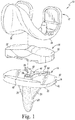
FIG. 1 is a perspective view of an orthopaedic prosthesis; -
FIG. 2 is a distal perspective view of a tibial tray component of the orthopaedic prosthesis ofFIG. 1 ; -
FIG. 3 is a distal plan view of the tibial tray component ofFIGS. 1-2 with the surface treatment removed for ease of viewing; -
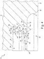
FIG. 4 is a partial cross-sectional elevation view of the tibial tray component ofFIGS. 1-3 taken along the line 4-4 inFIG. 3 and oriented such that the distal surface is facing toward the bottom edge of the illustration; -
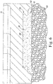
FIG. 5 is a perspective view illustrating the tibial tray component ofFIGS. 1-4 positioned for implantation into a patient's surgical-prepared tibia; and -
FIG. 6 is a partial cross-sectional elevation view of the tibial tray component when positioned on the patient's surgical-prepared tibia. - While the concepts of the present disclosure are susceptible to various modifications and alternative forms, specific exemplary embodiments thereof have been shown by way of example in the drawings and will herein be described in detail. It should be understood, however, that there is no intent to limit the concepts of the present disclosure to the particular forms disclosed, but on the contrary, the intention is to cover all modifications, equivalents, and alternatives falling within the spirit and scope of the invention as defined by the appended claims.
- Terms representing anatomical references, such as anterior, posterior, medial, lateral, superior, inferior, etcetera, may be used throughout the specification in reference to the orthopaedic implants or prostheses and surgical instruments described herein as well as in reference to the patient's natural anatomy. Such terms have well-understood meanings in both the study of anatomy and the field of orthopaedics. Use of such anatomical reference terms in the written description and claims is intended to be consistent with their well-understood meanings unless noted otherwise.
- Referring now to
FIG. 1 , a fixed-bearingknee prosthesis 10 is shown. Theknee prosthesis 10 includes afemoral component 12, atibial tray component 14, and aninsert component 16. Thetibial tray 14 includes a plate orplatform 18 and anelongated stem 20 that extends away from thedistal surface 22 of theplatform 18. Amedial keel 26 and alateral keel 24 are attached to thedistal surface 22 of theplatform 18 and extend along a portion of theelongated stem 20. The elongatedtibial stem 20 and thekeels proximal surface 152 of a patient's tibia 150 (seeFIG. 5 ). It should be appreciated that other fixation members, such as one or more short pegs or posts, may be used in lieu of theelongated stem 20. In the illustrative embodiment, the elongated stem includes an outer surface having a surface roughness (Ra) in a range of 3.5 microns to 6.5 microns. - The
insert component 16 is securable to thetibial tray 14 via a snap-fit. In such a way, theinsert 16 is fixed relative to the tibial tray 14 (i.e., it is not rotatable or moveable in the anterior/posterior or medial/lateral directions). Theinsert 16 includes a lateral bearingsurface 30 and a medial bearingsurface 32. Thebearing surfaces lateral condyle surface 34 and a convex curvedmedial condyle surface 36, respectively, of thefemoral component 12. - The
femoral component 12 is configured to be implanted into a surgically prepared end of the patient's femur (not shown), and is configured to emulate the configuration of the patient's natural femoral condyles. As such, thelateral condyle surface 34 and themedial condyle surface 36 are configured (e.g., curved) in a manner which mimics the condyles of the natural femur. Thelateral condyle surface 34 and themedial condyle surface 36 are spaced apart from one another thereby defining an intercondylar notch therebetween. - The components of the
knee prosthesis 10 that engage the natural bone, such as thefemoral component 12 and thetibial tray 14, may be constructed with a biocompatible metal, such as a cobalt chrome alloy, although other materials may also be used. The bone engaging surfaces of these components may be textured to facilitate cementing the component to the bone, as described in greater detail below. Such surfaces may also be porous coated to promote bone ingrowth for permanent fixation. - The
insert 16 may be constructed with a material that allows for smooth articulation between thebearing 16 and thefemoral component 12, such as a polymeric material. One such polymeric material is polyethylene such as ultrahigh molecular weight polyethylene (UHMWPE). - As shown in
FIG. 1 , thetibial tray 14 includes aproximal surface 40 that is positioned opposite thedistal surface 22 and a curvedouter wall 42 that extends between thesurfaces proximal surface 40 configured to receive theinsert 16, and, in the illustrative embodiment, includesbuttresses insert 16. As shown inFIG. 1 , thebuttress 44 has a pair ofarms platform 18. Each of thearms insert 16. Athird arm 56 of thebuttress 44 extends anteriorly away from the intersection of thelateral arm 50 and the medial arm 52 (i.e., in a direction toward the center of the platform 18). - Referring now to
FIG. 2 , thetibial tray 14 includes adistal pocket 60 in thedistal surface 22. In the illustrative embodiment, thepocket 60 extends around thekeels elongated stem 20 such that it has ananterior section 62 and twoposterior sections 64. It should be appreciated that in other embodiments thepocket 60 may be divided into multiple distal pockets. Thepocket 60 has a distal-facingopening 66 defined in thedistal surface 22. Aninner wall 70 extends inwardly (or proximally) from theopening 66 to anintermediate wall 72 of the tibial tray to define thepocket 60. Theinner wall 70 includes multiple curved surfaces that interconnected and surround thepocket 60. - In the illustrative embodiment, the
intermediate wall 72 includes a distal-facingsurface 74 that extends parallel to thedistal surface 22 of thetray 14. Each of thesurfaces surfaces - As shown in
FIG. 2 , thetibial tray 14 includes a plurality ofinner pockets 80, which are defined in theintermediate wall 72. Eachpocket 80 is fluidly connected to thedistal pocket 60 such that bone cement may enter thepockets pocket 80 has a distal-facingopening 82 defined in theintermediate wall 72. Arim wall 84 extends inwardly (or proximally) from theopening 82 to thebase wall 86 to define eachpocket 80, as described in greater detail below. Thebase wall 86 is substantially planar and extends parallel to thedistal surface 22 and theintermediate wall 72 in the illustrative embodiment. - As shown in
FIG. 3 , theinner pockets 80 include a pair ofanterior pockets keels keels 24, 26 (and hence thepockets 90, 92), respectively. As shown inFIG. 3 , configuration of theanterior pocket 90 mirrors that of theanterior pocket 92. Similarly, the configuration of theposterior pocket 94 mirrors that of theposterior pocket 96. In the illustrative embodiment, theanterior pockets stem 20, thekeels platform 18. - In the illustrative embodiment, each
inner pocket 80 has acentral recess 100 and an annular undercut or channel 102 (shown in broken line inFIG. 3 ) that extends around the perimeter 104 (seeFIG. 4 ) of therecess 100. The portion of thebase wall 86 of eachpocket 80 defining thecentral recess 100 has a surface roughness (Ra) in a range of 3.5 microns to 6.5 microns. In other embodiments, the surface roughness (Ra) may be greater than or equal to 3.5 microns and less than about 6.5 microns. It should also be appreciated that other portions of thebase wall 86 and therim wall 84 of eachpocket 80 may also have a surface roughness (Ra) in a range of 3.5 microns to 6.5 microns. - As described above, the
distal pocket 60 of the tibial tray has a distal-facingopening 66 defined in thedistal surface 22 of theplatform 18. As shown inFIG. 4 , aninner wall 70 extends inwardly (or proximally) from theopening 66 to anintermediate wall 72 to define thepocket 60. Eachinner pocket 80 has a distal-facingopening 82 defined in theintermediate wall 72. Therim wall 84 of eachpocket 80 extends inwardly (or proximally) from theopening 82 to thebase wall 86. - The
rim wall 84 of eachpocket 80 includes aconvex surface 110 that extends inwardly from theopening 82. Therim wall 84 also includes aconcave surface 112 that is connected to theconvex surface 110 and thebase wall 86. As shown inFIG. 4 , theconvex surface 110 includes adistal section 114 that extends along a straight line when thetibial tray 14 is viewed in a cross-sectional plane extending perpendicular to thedistal surface 22. Thedistal section 114 is connected to acurved surface section 116 at anedge 118. - The
curved surface section 116 has a constant radius of curvature R1 in the illustrative embodiment. The radius of curvature R1 is equal to about 0.15 millimeters but in other embodiments may be increased or decreased. It still other embodiments the radius of curvature may vary. As described in greater detail below, thecurved surface section 116 of eachrim wall 84 defines an inner-most edge 122 (shown in broken line inFIG. 4 ) of itsinner pocket 80. Thecurved surface section 116 is connected to aproximal section 124 of therim wall 84 at anedge 120. - As shown in
FIG. 4 , the proximalrim wall section 124 extends along a straight line when thetibial tray 14 is viewed in a cross-sectional plane extending perpendicular to thedistal surface 22. Therim wall section 124 extends proximally to anotheredge 126, where it connects to theconcave surface 112 of therim wall 84. Theconcave surface 112 connects to thebase wall 86 of eachpocket 80 at anedge 128. In the illustrative embodiment, thecurved surface section 116, the proximalrim wall section 124, theconcave surface 112,and anouter section 130 of thebase wall 86 cooperate to define the undercutchannel 102 of eachpocket 80. The undercutchannel 102 is sized to receive bone cement during implantation to create an interlock between thetibial tray 14 and the bone cement to assist with fixation of thetibial tray 14 to the patient's tibia. - In the illustrative embodiment, the
concave surface 112 has a constant radius of curvature R2. The radius of curvature R2 is equal to about 0.25 millimeters but in other embodiments may be increased or decreased. It still other embodiments the radius of curvature may vary. As shown in the cross-sectional illustration ofFIG. 4 , an angle α is defined between the distalrim wall section 114 and animaginary plane 134 extending parallel to thedistal surface 22. In the illustrative embodiment, the angle α is equal to about 60 degrees. It should be appreciated that in other embodiments the angle α may be about 45 degrees. An angle β is defined between the proximalrim wall section 124 and theplane 134. In the illustrative embodiment, the angle β is equal to about 45 degrees. Additionally, in the illustrative embodiment, thecurved surface section 116 extends along an arc between theedges - As described above, the
curved surface section 116 of eachrim wall 84 includes aninner-most edge 122 of itsinner pocket 80. In the illustrative embodiment, theinner-most edge 122 is positioned about 60 degrees along the arc of thecurved surface section 116 and lies in theplane 134 extending through theorigin 140 of the radius of curvature R1. Theinner-most edge 122 defines the peripheral edge of thenarrowest opening 142 of eachinner pocket 80, which, in the illustrative embodiment, includes theperimeter 104 of thecentral recess 100. Eachedge 122 extends alength 144 around the outer perimeter of therecess 100 and defines asurface area 146 of eachopening 142. Tables 1-2 below identifies thelengths 144 andsurface areas 146 for thepockets Table 1 Anterior Pocket 90Posterior Pocket 94Length 144 (mm) Surface Area 146 (mm2) Length 144 (mm) Surface Area 146 (mm2) 29.73 66.74 27.74 59.18 Table 2 Anterior Pocket 92Posterior Pocket 96Length 144 (mm) Surface Area 146 (mm2) Length 144 (mm) Surface Area 146 (mm2) 29.73 66.74 27.74 59.18 - In the illustrative embodiment, the sum of all of the
lengths 144 is equal to 114.94 mm, and the sum of all of thesurface areas 146 is equal to 251.84 mm2. The ratio of the sum of all of thelengths 144 to all of thesurface areas 146 is equal to 0.46. In other embodiments, the ratio may be greater than 0.20. In still other embodiments, the ratio may in a range of 0.31 to 0.46. It has been determined that this ratio affects the balance between the shear strength of the bone cement captured under therim walls 84 of theinner pockets 80 and the tensile strength of the cement "islands" formed in thenarrowest openings 82 of the inner pockets 80. For example, if the ratio is too high (e.g., the sum of the areas is only slightly greater than the sum of the lengths 144), then the benefit of the interlock fixation provided by capturing the bone cement under therim walls 84 will be limited by the reduced cement/bone fixation area for the "islands" of bone cement created at thenarrowest openings 82. If the ratio is too low (e.g., the sum of the areas is much greater than the sum of the lengths 144), then the potential for interlock fixation with therim wall 84 may not be achieved. - As described above, the
base wall 86 of eachpocket 80 has anedge 128 at which it connects to therim wall 84. Thebase wall 86 has a surface area defined within theedge 128 that is greater than thesurface area 146 of thenarrowest opening 142 of thepocket 80. In the illustrative embodiment, the surface area defined within theedge 128 is about 261.65 mm2. In other embodiments, it may be a range of 261.65 mm2 to 1670.00 mm2. - Referring now to
FIG. 5 , thetibial tray 14 is shown positioned for implantation into the patient'stibia 150. During a surgical procedure, an orthopaedic surgeon may use one or more instruments to define a surgically-preparedproximal surface 152 to receive theplatform 18 of thetibial tray 14. The orthopaedic surgeon also defines aproximal bore 154 that is sized to receive theelongated stem 20 and thekeels surface 152, the surgeon may apply alayer 156 of bone cement to thesurface 152 in advance of positioning thetibial tray 14 as shown inFIG. 5 . Additionally, in the illustrative embodiment, the proximal surface oftibial tray 14 is covered with aprotective coating 158 to protect the mating features during implantation. - With the
tray 14 positioned as shown inFIG. 5 , the surgeon may advance thetray 14 distally to insert thestem 20 and thekeels proximal bore 154. Theplatform 18 is advanced into contact with thecement layer 156, and the cement advances upward or proximally into thepockets tibial tray 14. As shown inFIG. 6 , when thetray 14 is seated,cement 160 fills thepockets channel 102, thereby creating an interlock between thetray 14 and thecement 160 and "islands" of bone cement in thenarrowest openings 82 of thepockets 80. Additionally, the surface roughness of thedistal surface 22, theintermediate wall 72, and thebase wall 86 has been unexpectedly shown to inhibit infiltration of lipid/marrow during surgery, thereby offering increasing initial fixation between thetibial tray 14 and thecement 160. - While the disclosure has been illustrated and described in detail in the drawings and foregoing description, such an illustration and description is to be considered as exemplary and not restrictive in character, it being understood that only illustrative embodiments have been shown and described and that all changes and modifications that come within the spirit of the disclosure are desired to be protected.
- There are a plurality of advantages of the present disclosure arising from the various features of the apparatus described herein. It will be noted that alternative embodiments of the apparatus of the present disclosure may not include all of the features described yet still benefit from at least some of the advantages of such features. Those of ordinary skill in the art may readily devise their own implementations of the apparatus that incorporate one or more of the features of the present invention and fall within the scope of the present invention as defined by the appended claims.
Claims (10)
- An orthopaedic prosthetic component (14), comprising:a plate (18) including a distal surface (22), a distal-facing opening (66) defined in the distal surface, a proximal surface (40) configured to receive an insert component (16), and a curved outer wall (42) extending between the distal surface and the proximal surface, andan elongated stem (20) extending from the distal surface of the plate to a distal tip,wherein the plate further includes an intermediate wall (72) positioned between the proximal surface and the distal surface, and an inner wall (70) that extends inwardly from the distal-facing opening to the intermediate wall to define a distal pocket (60),wherein the plate further includes a plurality of inner pockets (80) in the intermediate wall, each inner pocket being defined by a base wall (86) that is positioned proximal of the intermediate wall and a rim wall (84) that extends between an opening in the intermediate wall and the base wall, and each inner pocket including an annular channel (102) positioned between the intermediate wall and the base wall, andcharacterised in that the distal surface and the intermediate wall have a surface roughness (Ra) in a range of 3.5 microns to 6.5 microns,wherein each rim wall includes a convex distal surface (110) and a concave proximal surface (112) that cooperate to define the annular channel,wherein each inner pocket includes a narrowest opening (142) extending parallel to the base wall of the inner pocket that is defined by the convex distal surface of the rim wall, andthe narrowest opening of the inner pocket has a surface area that is less than the surface area of the base wall of the inner pocket, andwherein an imaginary line on the convex distal surface defines a peripheral edge (122) of the narrowest opening of each inner pocket, the peripheral edge having a peripheral edge length and defining a surface area of the narrowest opening of the inner pocket, the plate has a total peripheral edge length that is equal to the sum of the peripheral edge lengths of the plurality of inner pockets, and the plate has a total opening surface area that is equal to the sum of the surface areas of the narrowest openings of the plurality of inner pockets, and a ratio of the total peripheral edge length to the total opening surface area is greater than 0.20.
- The orthopaedic prosthetic component (14) of claim 1, wherein the plurality of inner pockets (80) includes an anterior pocket (90) and a posterior pocket (94) positioned posterior of the anterior pocket.
- The orthopaedic prosthetic component (14) of claim 2, wherein the anterior pocket (90) is one of a plurality of anterior pockets and the posterior pocket (94) is one of a plurality of posterior pockets.
- The orthopaedic prosthetic component (14) of claim 3, further comprising:a medial keel (26) connected to the elongated stem (20) and the distal surface (22) of the plate (18) and positioned between a first anterior pocket (90) and a first posterior pocket (94), anda lateral keel (24) connected to the elongated stem and the distal surface of the plate and positioned between a second anterior pocket and a second posterior pocket.
- The orthopaedic prosthetic component (14) of claim 3, wherein each anterior pocket is larger than each posterior pocket.
- The orthopaedic prosthetic component (14) of claim 1, wherein at least a portion of each base wall (86) has a surface roughness (Ra) in a range of 3.5 microns to 6.5 microns.
- The orthopaedic prosthetic component of claim 1, wherein the ratio of the total peripheral edge length to the total inner opening surface area is in a range of 0.31 to 0.46.
- The orthopaedic prosthetic component of claim 1, wherein the proximal surface of the plate includes a buttress configured to engage the insert component.
- The orthopaedic prosthetic component of claim 1, wherein the inner wall that defines the distal pocket includes multiple interconnected curved surfaces.
- The orthopaedic prosthetic component of claim 1, wherein the elongated stem includes an outer surface having a surface roughness (Ra) in a range of 3.5 microns to 6.5 microns.
Priority Applications (1)
| Application Number | Priority Date | Filing Date | Title |
|---|---|---|---|
| EP19206702.3A EP3626209B1 (en) | 2017-05-09 | 2018-05-08 | Tibial tray with fixation features |
Applications Claiming Priority (1)
| Application Number | Priority Date | Filing Date | Title |
|---|---|---|---|
| US15/590,537 US10307260B2 (en) | 2017-05-09 | 2017-05-09 | Tibial tray with fixation features |
Related Child Applications (2)
| Application Number | Title | Priority Date | Filing Date |
|---|---|---|---|
| EP19206702.3A Division EP3626209B1 (en) | 2017-05-09 | 2018-05-08 | Tibial tray with fixation features |
| EP19206702.3A Division-Into EP3626209B1 (en) | 2017-05-09 | 2018-05-08 | Tibial tray with fixation features |
Publications (2)
| Publication Number | Publication Date |
|---|---|
| EP3400911A1 EP3400911A1 (en) | 2018-11-14 |
| EP3400911B1 true EP3400911B1 (en) | 2020-01-01 |
Family
ID=62142982
Family Applications (2)
| Application Number | Title | Priority Date | Filing Date |
|---|---|---|---|
| EP19206702.3A Active EP3626209B1 (en) | 2017-05-09 | 2018-05-08 | Tibial tray with fixation features |
| EP18171207.6A Active EP3400911B1 (en) | 2017-05-09 | 2018-05-08 | Tibial tray with fixation features |
Family Applications Before (1)
| Application Number | Title | Priority Date | Filing Date |
|---|---|---|---|
| EP19206702.3A Active EP3626209B1 (en) | 2017-05-09 | 2018-05-08 | Tibial tray with fixation features |
Country Status (8)
| Country | Link |
|---|---|
| US (3) | US10307260B2 (en) |
| EP (2) | EP3626209B1 (en) |
| JP (2) | JP7126855B2 (en) |
| AU (2) | AU2018203221B2 (en) |
| BR (1) | BR102018009397B1 (en) |
| CA (1) | CA3004229A1 (en) |
| ES (2) | ES2776891T3 (en) |
| RU (1) | RU2018117025A (en) |
Families Citing this family (9)
| Publication number | Priority date | Publication date | Assignee | Title |
|---|---|---|---|---|
| US10182917B2 (en) * | 2016-04-11 | 2019-01-22 | Arthrex, Inc. | Components for artificial joints |
| US10307260B2 (en) | 2017-05-09 | 2019-06-04 | Depuy Ireland Unlimited Company | Tibial tray with fixation features |
| BR112020019445A2 (en) | 2018-03-26 | 2021-01-05 | DePuy Synthes Products, Inc. | THREE-DIMENSIONAL POROUS STRUCTURES FOR BONE INTERNAL GROWTH AND PRODUCTION METHODS |
| RU2020135533A (en) * | 2018-03-30 | 2022-05-05 | Депуи Синтез Продактс, Инк. | COMBINED FIXING ELEMENTS OF THREE-DIMENSIONAL POROUS STRUCTURES FOR BONE INGRINGING AND METHODS FOR THEIR MANUFACTURE |
| EP3758653B1 (en) | 2018-03-30 | 2024-03-06 | DePuy Synthes Products, Inc. | Surface textures for three-dimensional porous structures for bone ingrowth |
| US11517438B2 (en) | 2019-09-25 | 2022-12-06 | Depuy Ireland Unlimited Company | Three-dimensional porous structures for bone ingrowth and methods for producing |
| CN111281614B (en) * | 2020-03-11 | 2022-03-25 | 北京市春立正达医疗器械股份有限公司 | Knee joint prosthesis |
| WO2023150221A1 (en) * | 2022-02-03 | 2023-08-10 | Jackson James M | Systems and methods for magnetic joints |
| EP4285869A1 (en) | 2022-06-02 | 2023-12-06 | CeramTec GmbH | Tibial tray, tibial insert and an artificial knee joint |
Family Cites Families (8)
| Publication number | Priority date | Publication date | Assignee | Title |
|---|---|---|---|---|
| US4938769A (en) | 1989-05-31 | 1990-07-03 | Shaw James A | Modular tibial prosthesis |
| US5152797A (en) * | 1991-10-25 | 1992-10-06 | Johnson & Johnson Orthopaedics, Inc. | Modular prosthesis |
| WO1996029030A1 (en) | 1995-03-17 | 1996-09-26 | Smith & Nephew Richards Inc. | Medical implants |
| US6500208B1 (en) | 1998-10-16 | 2002-12-31 | Biomet, Inc. | Nonmodular joint prosthesis convertible in vivo to a modular prosthesis |
| US7628818B2 (en) | 2007-09-28 | 2009-12-08 | Depuy Products, Inc. | Fixed-bearing knee prosthesis having interchangeable components |
| US8475536B2 (en) * | 2010-01-29 | 2013-07-02 | DePuy Synthes Products, LLC | Methods and devices for implants with improved cement adhesion |
| US9820858B2 (en) * | 2015-03-23 | 2017-11-21 | Modal Manufacturing, LLC | Knee implants and instruments |
| US10307260B2 (en) | 2017-05-09 | 2019-06-04 | Depuy Ireland Unlimited Company | Tibial tray with fixation features |
-
2017
- 2017-05-09 US US15/590,537 patent/US10307260B2/en active Active
-
2018
- 2018-05-08 EP EP19206702.3A patent/EP3626209B1/en active Active
- 2018-05-08 RU RU2018117025A patent/RU2018117025A/en unknown
- 2018-05-08 ES ES18171207T patent/ES2776891T3/en active Active
- 2018-05-08 EP EP18171207.6A patent/EP3400911B1/en active Active
- 2018-05-08 ES ES19206702T patent/ES2875937T3/en active Active
- 2018-05-08 CA CA3004229A patent/CA3004229A1/en active Pending
- 2018-05-08 JP JP2018089701A patent/JP7126855B2/en active Active
- 2018-05-09 BR BR102018009397-5A patent/BR102018009397B1/en active IP Right Grant
- 2018-05-09 AU AU2018203221A patent/AU2018203221B2/en active Active
-
2019
- 2019-06-04 US US16/430,852 patent/US11324600B2/en active Active
-
2022
- 2022-05-10 US US17/740,845 patent/US20220265431A1/en active Pending
- 2022-08-05 AU AU2022211895A patent/AU2022211895A1/en active Pending
- 2022-08-12 JP JP2022128863A patent/JP7358584B2/en active Active
Non-Patent Citations (1)
| Title |
|---|
| None * |
Also Published As
| Publication number | Publication date |
|---|---|
| EP3400911A1 (en) | 2018-11-14 |
| BR102018009397A2 (en) | 2018-12-04 |
| AU2018203221B2 (en) | 2022-05-19 |
| BR102018009397B1 (en) | 2023-11-14 |
| ES2875937T3 (en) | 2021-11-11 |
| US10307260B2 (en) | 2019-06-04 |
| RU2018117025A3 (en) | 2021-09-08 |
| US20220265431A1 (en) | 2022-08-25 |
| AU2018203221A1 (en) | 2018-11-29 |
| ES2776891T3 (en) | 2020-08-03 |
| EP3626209A1 (en) | 2020-03-25 |
| US20190282368A1 (en) | 2019-09-19 |
| RU2018117025A (en) | 2019-11-08 |
| JP7126855B2 (en) | 2022-08-29 |
| AU2022211895A1 (en) | 2022-09-01 |
| JP2018187392A (en) | 2018-11-29 |
| JP7358584B2 (en) | 2023-10-10 |
| CA3004229A1 (en) | 2018-11-09 |
| US11324600B2 (en) | 2022-05-10 |
| JP2022145952A (en) | 2022-10-04 |
| US20180325682A1 (en) | 2018-11-15 |
| EP3626209B1 (en) | 2021-04-28 |
Similar Documents
| Publication | Publication Date | Title |
|---|---|---|
| EP3400911B1 (en) | Tibial tray with fixation features | |
| US9724202B2 (en) | Femoral component of a knee prosthesis having an angled cement pocket | |
| EP1684672B1 (en) | High flexion articular insert | |
| US8216319B2 (en) | Method of repairing a knee joint | |
| US9398956B2 (en) | Fixed-bearing knee prosthesis having interchangeable components | |
| US8128703B2 (en) | Fixed-bearing knee prosthesis having interchangeable components | |
| EP1398006A2 (en) | Duo-fixation prosthetic joints | |
| EP1779813B1 (en) | Orthopaedic implant systems with anti-abrasion studs | |
| JP2008253771A (en) | Mobile bearing assembly | |
| US8287601B2 (en) | Femoral component of a knee prosthesis having an angled cement pocket | |
| US9138322B2 (en) | Knee prosthesis having cross-compatible dome and anatomic patella components | |
| AU2014200110A1 (en) | High flexion articular insert |
Legal Events
| Date | Code | Title | Description |
|---|---|---|---|
| PUAI | Public reference made under article 153(3) epc to a published international application that has entered the european phase |
Free format text: ORIGINAL CODE: 0009012 |
|
| STAA | Information on the status of an ep patent application or granted ep patent |
Free format text: STATUS: THE APPLICATION HAS BEEN PUBLISHED |
|
| AK | Designated contracting states |
Kind code of ref document: A1 Designated state(s): AL AT BE BG CH CY CZ DE DK EE ES FI FR GB GR HR HU IE IS IT LI LT LU LV MC MK MT NL NO PL PT RO RS SE SI SK SM TR |
|
| AX | Request for extension of the european patent |
Extension state: BA ME |
|
| STAA | Information on the status of an ep patent application or granted ep patent |
Free format text: STATUS: REQUEST FOR EXAMINATION WAS MADE |
|
| 17P | Request for examination filed |
Effective date: 20190502 |
|
| RBV | Designated contracting states (corrected) |
Designated state(s): AL AT BE BG CH CY CZ DE DK EE ES FI FR GB GR HR HU IE IS IT LI LT LU LV MC MK MT NL NO PL PT RO RS SE SI SK SM TR |
|
| GRAP | Despatch of communication of intention to grant a patent |
Free format text: ORIGINAL CODE: EPIDOSNIGR1 |
|
| STAA | Information on the status of an ep patent application or granted ep patent |
Free format text: STATUS: GRANT OF PATENT IS INTENDED |
|
| INTG | Intention to grant announced |
Effective date: 20190719 |
|
| GRAS | Grant fee paid |
Free format text: ORIGINAL CODE: EPIDOSNIGR3 |
|
| GRAJ | Information related to disapproval of communication of intention to grant by the applicant or resumption of examination proceedings by the epo deleted |
Free format text: ORIGINAL CODE: EPIDOSDIGR1 |
|
| GRAL | Information related to payment of fee for publishing/printing deleted |
Free format text: ORIGINAL CODE: EPIDOSDIGR3 |
|
| STAA | Information on the status of an ep patent application or granted ep patent |
Free format text: STATUS: REQUEST FOR EXAMINATION WAS MADE |
|
| GRAR | Information related to intention to grant a patent recorded |
Free format text: ORIGINAL CODE: EPIDOSNIGR71 |
|
| STAA | Information on the status of an ep patent application or granted ep patent |
Free format text: STATUS: GRANT OF PATENT IS INTENDED |
|
| INTC | Intention to grant announced (deleted) | ||
| GRAA | (expected) grant |
Free format text: ORIGINAL CODE: 0009210 |
|
| STAA | Information on the status of an ep patent application or granted ep patent |
Free format text: STATUS: THE PATENT HAS BEEN GRANTED |
|
| INTG | Intention to grant announced |
Effective date: 20191120 |
|
| AK | Designated contracting states |
Kind code of ref document: B1 Designated state(s): AL AT BE BG CH CY CZ DE DK EE ES FI FR GB GR HR HU IE IS IT LI LT LU LV MC MK MT NL NO PL PT RO RS SE SI SK SM TR |
|
| REG | Reference to a national code |
Ref country code: GB Ref legal event code: FG4D |
|
| REG | Reference to a national code |
Ref country code: CH Ref legal event code: EP Ref country code: AT Ref legal event code: REF Ref document number: 1218846 Country of ref document: AT Kind code of ref document: T Effective date: 20200115 |
|
| REG | Reference to a national code |
Ref country code: DE Ref legal event code: R096 Ref document number: 602018001852 Country of ref document: DE |
|
| REG | Reference to a national code |
Ref country code: IE Ref legal event code: FG4D |
|
| REG | Reference to a national code |
Ref country code: CH Ref legal event code: NV Representative=s name: E. BLUM AND CO. AG PATENT- UND MARKENANWAELTE , CH |
|
| REG | Reference to a national code |
Ref country code: NL Ref legal event code: FP |
|
| REG | Reference to a national code |
Ref country code: LT Ref legal event code: MG4D |
|
| PG25 | Lapsed in a contracting state [announced via postgrant information from national office to epo] |
Ref country code: LT Free format text: LAPSE BECAUSE OF FAILURE TO SUBMIT A TRANSLATION OF THE DESCRIPTION OR TO PAY THE FEE WITHIN THE PRESCRIBED TIME-LIMIT Effective date: 20200101 Ref country code: CZ Free format text: LAPSE BECAUSE OF FAILURE TO SUBMIT A TRANSLATION OF THE DESCRIPTION OR TO PAY THE FEE WITHIN THE PRESCRIBED TIME-LIMIT Effective date: 20200101 Ref country code: NO Free format text: LAPSE BECAUSE OF FAILURE TO SUBMIT A TRANSLATION OF THE DESCRIPTION OR TO PAY THE FEE WITHIN THE PRESCRIBED TIME-LIMIT Effective date: 20200401 Ref country code: FI Free format text: LAPSE BECAUSE OF FAILURE TO SUBMIT A TRANSLATION OF THE DESCRIPTION OR TO PAY THE FEE WITHIN THE PRESCRIBED TIME-LIMIT Effective date: 20200101 Ref country code: PT Free format text: LAPSE BECAUSE OF FAILURE TO SUBMIT A TRANSLATION OF THE DESCRIPTION OR TO PAY THE FEE WITHIN THE PRESCRIBED TIME-LIMIT Effective date: 20200527 Ref country code: RS Free format text: LAPSE BECAUSE OF FAILURE TO SUBMIT A TRANSLATION OF THE DESCRIPTION OR TO PAY THE FEE WITHIN THE PRESCRIBED TIME-LIMIT Effective date: 20200101 |
|
| REG | Reference to a national code |
Ref country code: ES Ref legal event code: FG2A Ref document number: 2776891 Country of ref document: ES Kind code of ref document: T3 Effective date: 20200803 |
|
| PG25 | Lapsed in a contracting state [announced via postgrant information from national office to epo] |
Ref country code: LV Free format text: LAPSE BECAUSE OF FAILURE TO SUBMIT A TRANSLATION OF THE DESCRIPTION OR TO PAY THE FEE WITHIN THE PRESCRIBED TIME-LIMIT Effective date: 20200101 Ref country code: SE Free format text: LAPSE BECAUSE OF FAILURE TO SUBMIT A TRANSLATION OF THE DESCRIPTION OR TO PAY THE FEE WITHIN THE PRESCRIBED TIME-LIMIT Effective date: 20200101 Ref country code: IS Free format text: LAPSE BECAUSE OF FAILURE TO SUBMIT A TRANSLATION OF THE DESCRIPTION OR TO PAY THE FEE WITHIN THE PRESCRIBED TIME-LIMIT Effective date: 20200501 Ref country code: HR Free format text: LAPSE BECAUSE OF FAILURE TO SUBMIT A TRANSLATION OF THE DESCRIPTION OR TO PAY THE FEE WITHIN THE PRESCRIBED TIME-LIMIT Effective date: 20200101 Ref country code: GR Free format text: LAPSE BECAUSE OF FAILURE TO SUBMIT A TRANSLATION OF THE DESCRIPTION OR TO PAY THE FEE WITHIN THE PRESCRIBED TIME-LIMIT Effective date: 20200402 Ref country code: BG Free format text: LAPSE BECAUSE OF FAILURE TO SUBMIT A TRANSLATION OF THE DESCRIPTION OR TO PAY THE FEE WITHIN THE PRESCRIBED TIME-LIMIT Effective date: 20200401 |
|
| REG | Reference to a national code |
Ref country code: DE Ref legal event code: R097 Ref document number: 602018001852 Country of ref document: DE |
|
| PG25 | Lapsed in a contracting state [announced via postgrant information from national office to epo] |
Ref country code: EE Free format text: LAPSE BECAUSE OF FAILURE TO SUBMIT A TRANSLATION OF THE DESCRIPTION OR TO PAY THE FEE WITHIN THE PRESCRIBED TIME-LIMIT Effective date: 20200101 Ref country code: SM Free format text: LAPSE BECAUSE OF FAILURE TO SUBMIT A TRANSLATION OF THE DESCRIPTION OR TO PAY THE FEE WITHIN THE PRESCRIBED TIME-LIMIT Effective date: 20200101 Ref country code: RO Free format text: LAPSE BECAUSE OF FAILURE TO SUBMIT A TRANSLATION OF THE DESCRIPTION OR TO PAY THE FEE WITHIN THE PRESCRIBED TIME-LIMIT Effective date: 20200101 Ref country code: DK Free format text: LAPSE BECAUSE OF FAILURE TO SUBMIT A TRANSLATION OF THE DESCRIPTION OR TO PAY THE FEE WITHIN THE PRESCRIBED TIME-LIMIT Effective date: 20200101 Ref country code: SK Free format text: LAPSE BECAUSE OF FAILURE TO SUBMIT A TRANSLATION OF THE DESCRIPTION OR TO PAY THE FEE WITHIN THE PRESCRIBED TIME-LIMIT Effective date: 20200101 |
|
| PLBE | No opposition filed within time limit |
Free format text: ORIGINAL CODE: 0009261 |
|
| STAA | Information on the status of an ep patent application or granted ep patent |
Free format text: STATUS: NO OPPOSITION FILED WITHIN TIME LIMIT |
|
| REG | Reference to a national code |
Ref country code: AT Ref legal event code: MK05 Ref document number: 1218846 Country of ref document: AT Kind code of ref document: T Effective date: 20200101 |
|
| 26N | No opposition filed |
Effective date: 20201002 |
|
| PG25 | Lapsed in a contracting state [announced via postgrant information from national office to epo] |
Ref country code: MC Free format text: LAPSE BECAUSE OF FAILURE TO SUBMIT A TRANSLATION OF THE DESCRIPTION OR TO PAY THE FEE WITHIN THE PRESCRIBED TIME-LIMIT Effective date: 20200101 Ref country code: AT Free format text: LAPSE BECAUSE OF FAILURE TO SUBMIT A TRANSLATION OF THE DESCRIPTION OR TO PAY THE FEE WITHIN THE PRESCRIBED TIME-LIMIT Effective date: 20200101 |
|
| PG25 | Lapsed in a contracting state [announced via postgrant information from national office to epo] |
Ref country code: SI Free format text: LAPSE BECAUSE OF FAILURE TO SUBMIT A TRANSLATION OF THE DESCRIPTION OR TO PAY THE FEE WITHIN THE PRESCRIBED TIME-LIMIT Effective date: 20200101 Ref country code: PL Free format text: LAPSE BECAUSE OF FAILURE TO SUBMIT A TRANSLATION OF THE DESCRIPTION OR TO PAY THE FEE WITHIN THE PRESCRIBED TIME-LIMIT Effective date: 20200101 |
|
| PG25 | Lapsed in a contracting state [announced via postgrant information from national office to epo] |
Ref country code: LU Free format text: LAPSE BECAUSE OF NON-PAYMENT OF DUE FEES Effective date: 20200508 |
|
| PG25 | Lapsed in a contracting state [announced via postgrant information from national office to epo] |
Ref country code: TR Free format text: LAPSE BECAUSE OF FAILURE TO SUBMIT A TRANSLATION OF THE DESCRIPTION OR TO PAY THE FEE WITHIN THE PRESCRIBED TIME-LIMIT Effective date: 20200101 Ref country code: MT Free format text: LAPSE BECAUSE OF FAILURE TO SUBMIT A TRANSLATION OF THE DESCRIPTION OR TO PAY THE FEE WITHIN THE PRESCRIBED TIME-LIMIT Effective date: 20200101 Ref country code: CY Free format text: LAPSE BECAUSE OF FAILURE TO SUBMIT A TRANSLATION OF THE DESCRIPTION OR TO PAY THE FEE WITHIN THE PRESCRIBED TIME-LIMIT Effective date: 20200101 |
|
| PG25 | Lapsed in a contracting state [announced via postgrant information from national office to epo] |
Ref country code: MK Free format text: LAPSE BECAUSE OF FAILURE TO SUBMIT A TRANSLATION OF THE DESCRIPTION OR TO PAY THE FEE WITHIN THE PRESCRIBED TIME-LIMIT Effective date: 20200101 Ref country code: AL Free format text: LAPSE BECAUSE OF FAILURE TO SUBMIT A TRANSLATION OF THE DESCRIPTION OR TO PAY THE FEE WITHIN THE PRESCRIBED TIME-LIMIT Effective date: 20200101 |
|
| PGFP | Annual fee paid to national office [announced via postgrant information from national office to epo] |
Ref country code: NL Payment date: 20220420 Year of fee payment: 5 |
|
| PGFP | Annual fee paid to national office [announced via postgrant information from national office to epo] |
Ref country code: FR Payment date: 20220408 Year of fee payment: 5 Ref country code: ES Payment date: 20220603 Year of fee payment: 5 |
|
| PGFP | Annual fee paid to national office [announced via postgrant information from national office to epo] |
Ref country code: BE Payment date: 20220420 Year of fee payment: 5 |
|
| PGFP | Annual fee paid to national office [announced via postgrant information from national office to epo] |
Ref country code: GB Payment date: 20230330 Year of fee payment: 6 |
|
| PGFP | Annual fee paid to national office [announced via postgrant information from national office to epo] |
Ref country code: IT Payment date: 20230412 Year of fee payment: 6 Ref country code: IE Payment date: 20230412 Year of fee payment: 6 Ref country code: DE Payment date: 20230331 Year of fee payment: 6 Ref country code: CH Payment date: 20230602 Year of fee payment: 6 |
|
| REG | Reference to a national code |
Ref country code: NL Ref legal event code: MM Effective date: 20230601 |
|
| REG | Reference to a national code |
Ref country code: BE Ref legal event code: MM Effective date: 20230531 |
|
| PG25 | Lapsed in a contracting state [announced via postgrant information from national office to epo] |
Ref country code: NL Free format text: LAPSE BECAUSE OF NON-PAYMENT OF DUE FEES Effective date: 20230601 |