EP1091588A1 - Image encoder and its method - Google Patents
Image encoder and its method Download PDFInfo
- Publication number
- EP1091588A1 EP1091588A1 EP00917388A EP00917388A EP1091588A1 EP 1091588 A1 EP1091588 A1 EP 1091588A1 EP 00917388 A EP00917388 A EP 00917388A EP 00917388 A EP00917388 A EP 00917388A EP 1091588 A1 EP1091588 A1 EP 1091588A1
- Authority
- EP
- European Patent Office
- Prior art keywords
- image
- encoding
- processing unit
- quantizer scale
- image processing
- Prior art date
- Legal status (The legal status is an assumption and is not a legal conclusion. Google has not performed a legal analysis and makes no representation as to the accuracy of the status listed.)
- Withdrawn
Links
Images




Classifications
-
- H—ELECTRICITY
- H04—ELECTRIC COMMUNICATION TECHNIQUE
- H04N—PICTORIAL COMMUNICATION, e.g. TELEVISION
- H04N19/00—Methods or arrangements for coding, decoding, compressing or decompressing digital video signals
- H04N19/10—Methods or arrangements for coding, decoding, compressing or decompressing digital video signals using adaptive coding
- H04N19/169—Methods or arrangements for coding, decoding, compressing or decompressing digital video signals using adaptive coding characterised by the coding unit, i.e. the structural portion or semantic portion of the video signal being the object or the subject of the adaptive coding
- H04N19/177—Methods or arrangements for coding, decoding, compressing or decompressing digital video signals using adaptive coding characterised by the coding unit, i.e. the structural portion or semantic portion of the video signal being the object or the subject of the adaptive coding the unit being a group of pictures [GOP]
-
- H—ELECTRICITY
- H04—ELECTRIC COMMUNICATION TECHNIQUE
- H04N—PICTORIAL COMMUNICATION, e.g. TELEVISION
- H04N19/00—Methods or arrangements for coding, decoding, compressing or decompressing digital video signals
- H04N19/10—Methods or arrangements for coding, decoding, compressing or decompressing digital video signals using adaptive coding
- H04N19/102—Methods or arrangements for coding, decoding, compressing or decompressing digital video signals using adaptive coding characterised by the element, parameter or selection affected or controlled by the adaptive coding
- H04N19/115—Selection of the code volume for a coding unit prior to coding
-
- H—ELECTRICITY
- H04—ELECTRIC COMMUNICATION TECHNIQUE
- H04N—PICTORIAL COMMUNICATION, e.g. TELEVISION
- H04N19/00—Methods or arrangements for coding, decoding, compressing or decompressing digital video signals
- H04N19/10—Methods or arrangements for coding, decoding, compressing or decompressing digital video signals using adaptive coding
- H04N19/102—Methods or arrangements for coding, decoding, compressing or decompressing digital video signals using adaptive coding characterised by the element, parameter or selection affected or controlled by the adaptive coding
- H04N19/119—Adaptive subdivision aspects, e.g. subdivision of a picture into rectangular or non-rectangular coding blocks
-
- H—ELECTRICITY
- H04—ELECTRIC COMMUNICATION TECHNIQUE
- H04N—PICTORIAL COMMUNICATION, e.g. TELEVISION
- H04N19/00—Methods or arrangements for coding, decoding, compressing or decompressing digital video signals
- H04N19/10—Methods or arrangements for coding, decoding, compressing or decompressing digital video signals using adaptive coding
- H04N19/102—Methods or arrangements for coding, decoding, compressing or decompressing digital video signals using adaptive coding characterised by the element, parameter or selection affected or controlled by the adaptive coding
- H04N19/124—Quantisation
-
- H—ELECTRICITY
- H04—ELECTRIC COMMUNICATION TECHNIQUE
- H04N—PICTORIAL COMMUNICATION, e.g. TELEVISION
- H04N19/00—Methods or arrangements for coding, decoding, compressing or decompressing digital video signals
- H04N19/10—Methods or arrangements for coding, decoding, compressing or decompressing digital video signals using adaptive coding
- H04N19/102—Methods or arrangements for coding, decoding, compressing or decompressing digital video signals using adaptive coding characterised by the element, parameter or selection affected or controlled by the adaptive coding
- H04N19/124—Quantisation
- H04N19/126—Details of normalisation or weighting functions, e.g. normalisation matrices or variable uniform quantisers
-
- H—ELECTRICITY
- H04—ELECTRIC COMMUNICATION TECHNIQUE
- H04N—PICTORIAL COMMUNICATION, e.g. TELEVISION
- H04N19/00—Methods or arrangements for coding, decoding, compressing or decompressing digital video signals
- H04N19/10—Methods or arrangements for coding, decoding, compressing or decompressing digital video signals using adaptive coding
- H04N19/134—Methods or arrangements for coding, decoding, compressing or decompressing digital video signals using adaptive coding characterised by the element, parameter or criterion affecting or controlling the adaptive coding
- H04N19/146—Data rate or code amount at the encoder output
- H04N19/15—Data rate or code amount at the encoder output by monitoring actual compressed data size at the memory before deciding storage at the transmission buffer
-
- H—ELECTRICITY
- H04—ELECTRIC COMMUNICATION TECHNIQUE
- H04N—PICTORIAL COMMUNICATION, e.g. TELEVISION
- H04N19/00—Methods or arrangements for coding, decoding, compressing or decompressing digital video signals
- H04N19/10—Methods or arrangements for coding, decoding, compressing or decompressing digital video signals using adaptive coding
- H04N19/169—Methods or arrangements for coding, decoding, compressing or decompressing digital video signals using adaptive coding characterised by the coding unit, i.e. the structural portion or semantic portion of the video signal being the object or the subject of the adaptive coding
- H04N19/17—Methods or arrangements for coding, decoding, compressing or decompressing digital video signals using adaptive coding characterised by the coding unit, i.e. the structural portion or semantic portion of the video signal being the object or the subject of the adaptive coding the unit being an image region, e.g. an object
- H04N19/176—Methods or arrangements for coding, decoding, compressing or decompressing digital video signals using adaptive coding characterised by the coding unit, i.e. the structural portion or semantic portion of the video signal being the object or the subject of the adaptive coding the unit being an image region, e.g. an object the region being a block, e.g. a macroblock
-
- H—ELECTRICITY
- H04—ELECTRIC COMMUNICATION TECHNIQUE
- H04N—PICTORIAL COMMUNICATION, e.g. TELEVISION
- H04N19/00—Methods or arrangements for coding, decoding, compressing or decompressing digital video signals
- H04N19/60—Methods or arrangements for coding, decoding, compressing or decompressing digital video signals using transform coding
- H04N19/61—Methods or arrangements for coding, decoding, compressing or decompressing digital video signals using transform coding in combination with predictive coding
Definitions
- the present invention relates to an apparatus for encoding an image, more particularly relates to an image encoder capable of encoding a moving picture at a variable bit rate and a method of the same.
- the digitized image signal is encoded at a constant bit rate or at a variable bit rate.
- a bit stream encoded at a constant bit rate has a constant bit rate and does not depart much from an object bit rate.
- a bit stream encoded at a variable bit rate does not have a constant bit rate and varies in accordance with the characteristics of the image signal to be encoded. Note that in this case, compression and encoding are performed on an image signal within a range not exceeding a maximum bit rate subscribed by standards.
- encoding bit rate control that is, control so as to give a desired bit rate when viewing a certain time span of a coding series generated by encoding.
- a plurality of standards for compressing and encoding an image signal changing over time, a so-called motion picture, at a high efficiency have been proposed hitherto.
- the MPEG2 standard has currently gathered attention and come into practical use in a variety of fields of application such as communication, broadcasting, and media storage.
- Digital versatile disks (DVD) one of the applications, is expected to be increasingly widely used in the future as recording media for compressing, encoding, and storing motion pictures based on the MPEG2 standard due to its large capacity, low cost, and ease in handling.
- the MPEG2 standard does not define the above encoding control for control of the bit rate. Therefore, it is sufficient that the amount of encoded information be within a certain range subscribed by standards.
- a variable bit rate is used in authoring DVDs (editing work for preparing a DVD title).
- the encoding method at this time investigates the encoding difficulty of the source as a whole in a first encoding and performs encoding assigning an amount of code corresponding to the encoding difficulty in the second encoding to realize a variable bit rate. As a result, a larger code amount is assigned to an image signal having a high difficulty, while a code amount assigned to an image signal having a low difficulty is suppressed and therefore uniformity of the image quality can be attained.
- the successively input motion picture signal has to be compressed, encoded, and recorded sequentially.
- the image is normally compressed and encoded at a constant bit rate using a fixed code amount for every GOP (group of pictures) in units of, for example, about 15 frames.
- Figure 7 is a view of a view of an encoding rate when encoding an image signal at a constant bit rate.
- a bit rate of an obtained coding series is made constant to be almost an object bit rate regardless of the characteristics of the image.
- a bit rate control portion of the image encoder rapidly changes a quantizer scale in units of macroblocks comprised of a several blocks for the object bit rate given in advance.
- the compression and encoding by a constant bit rate make the bit rate constant regardless of the characteristic of the image signal, therefore the picture quality is good in a scene wherein the encoding difficulty is low, but there is a disadvantage that the picture quality deteriorates in a scene wherein the encoding difficulty is high.
- FIG. 8 is an example of a bit rate of a coding series obtained by variable bit rate control.
- the quantizer scale is controlled for example in units of GOPs fro an object bit rate. Namely, a response speed of the quantizer scale is made slow.
- the bit rate becomes low in portions where encoding difficulty is low, while the bit rate becomes high in portions where encoding difficulty is high.
- the bit rate is set based on experience. Since images obtained from an actual image pickup device changes from moment to moment and the encoding difficulty also changes over time, the encoding bit rate exceeds a maximum bit rate designated at a sequence header at the top of a bit stream in the portions where encoding difficulty is high in some cases. Therefore, it is impossible to generate a bit stream based on standards in all cases merely by making the response speed of the quantizer scale in accordance with changes of encoding difficulty.
- the present invention was made in consideration with such a circumstance and has as an object thereof to provide an image encoder and processing method capable of realizing compression and encoding of a motion picture at a variable bit rate in an application where real time processing is required.
- an image encoder of the present invention claims*.
- Figure 1 is a view of the configuration of an embodiment of an image encoder according to the present invention.
- an image encoder of the present invention comprises a control circuit 10, an encoder 20, and an image input device 30.
- the control circuit 10 respectively outputs to the image input circuit 30 and the encoder 20 control signals S12 and S13 in accordance with a control signal S1 input from the outside and controls their operations.
- the image input device 30 outputs image data S30 obtained by digitizing the image signal to the encoder 20.
- the image input device is any pickup such as a video camera or image reproducing apparatus for reproducing an image signal from another recording medium and need only have the function of generating an image signal by some means and converting an image signal in an analog format to a digital signal.
- the image input device 30 generates image information data S32 in accordance with a type, characteristics, etc. of the input image signal and supplies the same to the control circuit 10.
- the control circuit 10 receives the image information data S32 and outputs a compression and encoding parameter S12 to the encoder 20 in accordance with the characteristics etc. of the input image signal.
- the compression and encoding parameter S12 is comprised of a plurality of parameters or signals such as an object bit rate, maximum bit rate, and variable bit rate instruction signal which will be explained later on.
- the encoder 20 performs, in accordance with the compression and encoding parameter S12 from the control circuit 10, compression and encoding on the digital image data S30 sent from the image input device 30 based on a predetermined algorithm and outputs a bit stream S20.
- the amount of data of the bit stream S20 is greatly reduced compared with the image data S30 before being subjected to the compression and encoding.
- the transfer capacity of a channel or a storage capacity of an image recording medium can be greatly reduced by transferring or storing of information of the bit stream S20 compressed and encoded by the encoder 20.
- an appropriate bit rate can be set in accordance with characteristics of the image data and a uniform picture quality of the entire image and the compression efficiency can be improved.
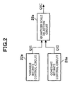
- Figure 2 is a block diagram of the configuration of the encoder 20 in the present embodiment.
- the encoder 20 comprises a variable bit rate control circuit 22a, a constant bit rate control circuit 23a and a quantizer scale select circuit 25a.
- the variable bit rate control circuit 22a is a first quantizer scale setting means for setting a first quantizer scale for performing image encoding in a first image processing unit and setting a gently changing first quantizer scale QS1 in accordance with encoding difficulty of an input image signal in units of a first image processing unit, for example, in units of GOPS comprised of a plurality of pictures with respect to an object bit rate.
- the constant bit rate control circuit 23a is a second quantizer scale setting means for setting a rapidly changing second quantizer scale QS2 in order not to exceed a maximum bit stream with respect to the maximum bit stream designated by a sequence header at the top of the bit stream in units of a second image processing unit, for example, in units of pictures or macroblocks, which is shorter than said first image processing unit (GOP)
- the image encoder of the present embodiment obtains a gently changing first quantizer scale QS1 in units of long image processing unit, for example, in units of GOPs with respect to an object encoding bit rate in accordance with encoding difficulty of an input image, obtains a quickly changing second quantizer scale QS2 in units of short image processing units, for example, in units of macroblocks with respect to a maximum bit rate prescribed by standards, furthermore, selects the larger of the two as a quantizer scale QSC for performing encoding on the input image.
- an input image signal can be encoded at an encoding bit rate close to the object bit rate in average corresponding to the encoding difficulty of the input image signal, and it becomes possible to guarantee not to exceed the maximum bit rate prescribed by the standards.
- FIG. 3 is a view of a specific example for realizing the image encoding processing of the present invention and is a block diagram of the configuration of an encoder 20.
- the encoder 20 comprises a VBR buffer memory 21, VBR controller 22, CBR controller 23, image compression encoder 24, and quantizer scale comparator 25.
- VBR buffer memory 21 As shown in Fig. 3, the encoder 20 comprises a VBR buffer memory 21, VBR controller 22, CBR controller 23, image compression encoder 24, and quantizer scale comparator 25.
- the VBR buffer memory 21 holds a parameter VBRb called a VBR buffer value (hereinafter referred to as a VBR buffer value) and is provided for making the amount of deviation from an object bit rate in a series of encoding processing small in total value.
- VBR buffer value a parameter VBRb called a VBR buffer value (hereinafter referred to as a VBR buffer value) and is provided for making the amount of deviation from an object bit rate in a series of encoding processing small in total value.
- VBR buffer value a parameter VBRb
- the VBR buffer memory 21 stores a VBR buffer initial value INI input from the control circuit 10 shown in Fig. 1.
- the simplest method of initializing is, before starting the processing, to initialize in accordance with an initialize control signal from the control circuit 10 and to set the initializing value to be "0" or a value given in advance.
- the initial value INI stored in the VBR controller 20 is provided, the VBR buffer value VBRb is input from the VBR controller 22 at the time of completing the encoding, which is stored, and the stored VER buffer value VBRb is output to the VBR controller 22 in the next encoding.
- the VBR controller 22 sets a VBR quantizer scale VBRq in accordance with a VBR response value VRT, object bit rate BR obj , and maximum bit rate BR max input from the control circuit 10 and outputs the same to the quantizer scale comparator 25.
- the VBR controller 22 has as internal parameters the VBR buffer value VBRb for obtaining an output VBR quantizer scale, a remaining bit quantity RBG in a GOP at the time of encoding at the object bit rate, and a response speed VBRr indicating a response speed of the VBR quantizer scale.
- VBRq VBRb/(2 n ⁇ VBRr)
- the quantizer scale VBRq when the coding type is a B-picture is made the quantizer scale VBRq when the coding type is a B-picture. Namely, when in the case of a B-picture, the quantizer scale is always set to be quantizer scales of I- and P-pictures multiplied with 1.4.
- the quantizer scales of the I/P/B-pictures are determined in a simple method as explained above, but by inspecting the encoding difficulties of the respective pictures, the quantizer scales can be made different in accordance therewith.
- An object bit quantity for every GOP is set in the remaining bit quantity RBG in the GOP. Then, for example when a generated bit quantity for every MB (macro block) is received, the amount is subtracted from the object bit quantity. The amount of deviation from the object bit quantity remains in the RBG at the end of each GOP, thus, which is subtracted from the VBR buffer value VBRb. At this time, when the VBR buffer value VBRb becomes negative, it is set to be "0". Also, when the VBR buffer value VBRb comes close to overflowing, it is fixed to be a maximum value.
- VBRb the initial value of the VBR buffer value VBRb at the time of starting encoding is input from the VBR buffer memory 21.
- VBRb m ⁇ VBRr/(BR obj ⁇ 2 k )
- Equation (2) m and k are calculation parameters.
- the response speed VBRr in equation (2) a value supplied from the control circuit 10 shown in Fig. 1 is used. For example, when the response speed VBRr is set at about 200, a response speed of tens of seconds is obtained, while when set at about 4000, a response speed of tens of minutes is obtained.
- the VBR buffer value VBRb calculated from equation (2) is transferred to the VBR buffer memory 21 and stored therein.
- RBG BR obj ⁇ N/PCR
- N is the interval of I-pictures and PCR is a picture rate.
- the CBR controller 23 sets a CBR quantizer scale CBRq in response to the object bit rate BR obj , maximum bit rate BR max , and VBR instruction signal VBD input from the control circuit 10 and outputs the same to the quantizer scale comparator 25.
- the CBR controller 23 performs, for example, rate control of the CBR based on an algorithm of a test mode 5 (TM5) prescribed by the MPEG2 standards.
- TM5 test mode 5
- image encoding processing is performed in units of GOPs.
- a bit amount R to be assigned to a GOP is determined from the number of pictures and bit rates included in every GOP.
- a remaining amount ⁇ R (positive or negative) of the bit amount in the previous GOP of the GOP being processed is added to the amount of on-going processing.
- an object bit amount for a picture to be encoded from now is determined from the bit amount R for every picture and encoding difficulty of each of the picture types (I/B/P). Then, a bit amount actually generated after completing the encoding is subtracted from the object bit amount and a remaining amount ⁇ R of the bit amount is calculated.
- the quantizer scale In processing in units of macroblocks (MB), pictures are encoded in units of MBs, and when the generated bit amount comes close to exceed the object bit amount in every MB, the quantizer scale is set to be large, while when the generated bit amount comes close to be under the object bit amount, the quantizer scale is set to be small. Furthermore, considering the fact that human visual characteristics is sensitive to deterioration of picture quality on a flat portion in a screen, the quantizer scale is set to be large in a portion where an image is relatively flat, while the quantizer scale lis set to be small in a fine image portion.
- image encoder of the present invention is not limited to performing rate control in CBR based on an algorithm of TM5, and may perform the rate controlling based on other control format.
- the CBR controller 23 in the image encoder of the present embodiment is a CBR controller installed in an MPEG encoder of the related art being improved.
- the CBR controller 23 of the present embodiment is additionally given the functions below.
- the CBR controller 23 controls the CBR quantizer scale 1 in accordance with the VBR instruction signal VBD input from the control circuit 10 shown in Fig. 1. Specifically, when the VBR instruction signal is "0", the rate is controlled based on the object bit rate BR obj , while when the VBR instruction signal VBD is "1", the rate is controlled based on the maximum bit rate BR max . Namely, when the VBR instruction signal VBD is "0", normal CBR rate control is performed and the quantizer scale is controlled so that the bit rate of a bit stream obtained by the compression and encoding does not deviate with respect to the object bit rate BR obj . On the other hand, when the VBR instruction signal VBD is "1", the VBR rate is controlled and the quantizer scale is controlled so that the bit stream obtained in the compression and encoding does not exceed the maximum bit rate BR max .
- the next GOP's object bit rate R is determined in the TM5 of the MPEG2 for every GOP.
- the R is subtracted from a bit quantity generated in the GOP. After that, this is deemed the remaining bit quantity of the GOP and indicated by ⁇ R.
- the remaining bit quantity ⁇ R is added to the object bit quantity R of the next GOP, but when the VBR instruction signal VBD is "1", the processing is not performed. This is because when the VBR instruction signal VBD is "1", the quantizer scale is controlled by the VBR rate control and the object bit quantity R is left at the end of the next GOP in the most cases (namely, ⁇ R>0).
- VBV video buffering verifier
- the next GOP's object bit rate is determined for every GOP in the TM5 of the MPEG2. Due to the above additional functions, the CBR controller 23 of the present embodiment performs three different kinds of processing as described below in accordance with the input VBR instruction signal VBD, and the next GOP's object bit quantity R is determined.
- the above case 1 is the same processing as the normal processing of the TM5 of the MPEG2.
- the CBR is controlled.
- the remaining bit quantity ⁇ R for every GOP is always fed back to the next GOP's object bit quantity R i+1 , which is corrected in accordance with the remaining bit quantity ⁇ R i of the immediately before GOP.
- the VBR is controlled and the next GOP's object bit quantity is calculated in accordance with the remaining bit quantity ⁇ R of every GOP so as not to exceed the maximum bit rate BR max .
- the remaining bit quantity ⁇ R i is negative in the GOP immediately before, as shown in equation (5), the remaining bit quantity ⁇ R i is fed back to the next GOP's object bit quantity in the GOP immediately before and the next GOP's object bit quantity R i+1 is corrected to be less.
- the CBR controller 23 obtains the CBR quantizer scale CBRq based on the GOP's object bit quantity calculated as above and supplies the same and the VBR quantizer scale VBRq obtained in the VBR controller 22 to the quantizer scale comparator 25.
- the quantizer scale comparator 25 calculates a base quantizer scale QSC in accordance with the VBR quantizer scale VBRq, CBR quantizer scale CBRq, and VBR instruction signal VBD input from the CBR controller 23 and supplies the same to the image compression encoder 24.
- the quantizer scale comparator 25 outputs the CBR quantizer scale CBRq to the image compression encoder 24.
- the quantizer scale is controlled so that the bit rate does not always largely depart from the object bit rate BR obj .
- the quantizer scale comparator 25 compares the VBR quantizer scale VBRq with the CBR quantizer scale CBRq and outputs the larger to the image compression encoder 24. As a result, the bit rate is controlled based on the VBR rate control, and the quantizer scale is controlled so that the bit rate does not exceed the maximum bit rate BR max .
- the image compression encoder 24 compresses and encodes the image data S30 input from the image input device 30 shown in Fig. 1 in accordance with the object bit rate BR obj , maximum bit rate BR max , VBR instruction signal VBD, and quantizer scale QSC supplied from the quantizer scale comparator 25 and outputs a bit stream BSM.
- the bit stream BSM is identical with an output signal S20 from the encoder 20 in Fig. 1.
- the image compression encoder 24 generates a bit quantity BQT indicating a bit quantity generated by the compression and encoding and a PCT signal indicating a picture coding type and outputs them to the VBR controller 22 and the CBR controller 23, respectively.
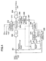
- Figure 4 is a block diagram of an example of the configuration of the image compression encoder 24. Below, the configuration and operations of the image compression encoder 24 will be explained with reference to Fig. 4.
- the image compression encoder 24 comprises an adder 201, a DCT portion 202, a quantizer 203, a variable length coder (VLC) 204, an inverse quantizer 205, an inverse DCT portion 206, an adder 207, a frame memory 208, a motion detector 209, a motion compensator 210, a switch circuit 211, and encoding controller 212.
- VLC variable length coder
- the difference of the image signal S30 input to the image compression encoder 24 and a reproduction image signal input from the switch circuit 211 is obtained in the adder 201 and output to the DCT portion 202.
- I-picture intra-picture
- a meaningful image is not input from the switch circuit 211 (the output from the switch circuit during this mode is "0" in Fig. 4), so the image data input to the adder 201 is output as it is to the DCT portion 202.
- a motion compensation prediction mode image data based on an image reproduced before that is input from the switch circuit 211, so the difference is obtained in the adder 201 and the error is input to the DCT portion 202.
- the DCT portion 202 performs discrete cosine transform (DCT) on the image signal input from the adder 201 to reduce spatial redundancy.
- DCT discrete cosine transform
- a transform coefficient obtained by the DCT is input to the quantizer 203.
- the quantizer 203 quantizes the transform coefficient obtained from the DCT portion 202 in accordance with the quantization rate input from the controller 213 and outputs it to the variable length coder 204 and inverse quantizer 205. Note that the quantizer scale of the quantizer 203 is controlled by the encoding controller 212.
- variable length coder 204 encodes the quantized transform coefficient to a variable length to generate an encoded image bit stream S20 and successively outputs the same.
- the encoding controller 212 controls the quantization rate of the quantizer 203, recording of image data to a frame memory 208, switching of the switch circuit, etc. As shown in the figure, the encoding controller 212 sets a predetermined quantizer scale to the quantizer 203 in accordance with the object bit rate BR obj input from the control circuit shown in Fig. 1, maximum bit rate BR max , VBR instruction signal VBD, and quantizer scale QSC from the quantizer scale comparator 25 shown in Fig. 3 and controls the quantization rate.
- the transform coefficient quantized by the quantizer 203 is input to the inverse quantizer 205.
- the transform coefficient is inversely quantized in the inverse quantizer 205 and further subjected to an inverse discrete cosine transform (inverse DCT) in the inverse DCT portion 206.
- inverse DCT inverse discrete cosine transform
- the inversely DCT'ed image signal and an image signal obtained by the above motion compensation prediction are added in the adder 207 to be returned to the original image signal and stored in the frame memory 208.
- the image signal inversely DCT'ed in the inverse DCT portion 206 is stored as it is in the frame memory 208.
- the image signal stored in a frame memory 208 is used. Namely, motion is detected in the motion detector 209 from the next image source signal to detect the motion vector based on the image signal stored in the frame memory 208. Furthermore, based on the motion vector, motion compensation prediction is performed in the motion compensator 210. Then, the image signal obtained by the motion compensation prediction is output to the adder 201 via the switch circuit 211 and the difference of the input image source signal is obtained.
- the image compression encoder 24 having the above configuration encodes the input image signal S30 to generate a bit stream.
- VBR instruction signal VBD is "0”
- an object bit rate BRobj is output to the bit rate of the sequence header
- the VBR instruction signal VBD is "1”
- the maximum bit rate BRmax is output to the bit rate.
- a quantizer scale is set for each of the macro blocks (MB), based thereon, the quantizer scale is changed aiming at the visual effect based on step 3 of bit rate control in the TM5 of the MPEG2 and the changed quantizer scale is used for quantization. Then, a bit stream generated for every MB is output.
- the image compression encoder 24 has the general function of an image encoding device in the MPEG2 of preventing a VBV from underflowing by forcibly cutting a DCT coefficient when the bit rate control by using the quantizer scale is not performed well.
- image compression encoder 24 it is possible to realize encoding of an image signal at a variable bit rate by one encoding operation, that is, by one path processing. Therefore, for example in an image processing apparatus picking up and recording an image in real time such as a video camera, image encoding at a variable bit rate can be realized by one encoding operation, and uniformity of picture quality can be realized in an image signal having different characteristics, and furthermore the encoding efficiency can be improved by variable bit rate control.
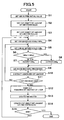
- Figure 5 is a flow chart of the operation of an image encoder of the present embodiment. Below, the operation of the image encoder of the present embodiment will be explained by using specific examples of parameter values with reference to Fig. 5.
- Figure 5 is a flow chart of the operation when encoding an image at a variable bit rate, namely, a flow chart of image encoding in the case where the VBR instruction signal VBD in Fig. 3 is "1".
- VBR instruction signal VBD When the VBR instruction signal VBD is "0", the image is encoded at a normal constant bit rate, the next GOP's object bit quantity is calculated only in the CBR controller 23 from equation (4) in accordance with the object bit rate BR obj and the remaining bit quantity ⁇ R i in the GOP immediately before, and in accordance therewith, an encoding scale in the next GOP is controlled.
- the image is generally encoded based on the constant bit rate in an image encoder to which the normal MPEG2 standard is applied, so a detailed explanation of the operation will be omitted here.
- the initial value of the VBR buffer value VBRb is obtained from equation (2) in accordance with given parameters (step S1).
- BR obj 4Mbps
- maximum bit rate BR max 8Mbps
- VBR response speed VBRr 300
- the object bit quantity of the GOP is obtained in the VBR controller 22 based on equation (3).
- step S3 the GOP object bit rate is obtained in the CBR controller 23 in accordance with the maximum bit rate BR max .
- step S4 the processing shown in step S4 is performed.
- the VBR quantizer scale VBRq is obtained from equation (1) based on the VBR buffer value VBRb obtained above.
- step S5 the CBR quantizer scale CBRq is obtained in the CBR controller 23 in accordance with the maximum bit rate BR max .
- step S6 The processing shown in step S6 is performed in the quantizer scale comparator 25.
- the VBR quantizer scale VBRq and the CBR quantizer scale CBRq are compared and the larger, as a result of the comparison, is output to the image compression encoder 24 (steps S7 and S8).
- the image compression encoder 24 encodes the input image signal in units of 1 MB by using the quantizer scale provided from the quantizer scale comparator 25 (step S9). Then, as shown in step S10, a bit quantity generated from the encoding is subtracted from the set GOP object bit quantity. The processing from steps S4 to S10 are repeated until encoding all of the image signal of 1 GOP. After completing the encoding on 1 GOP, a remaining bit quantity RBG of the 1 GOP is taken out in step S12. The VBR buffer value is updated in the VBR controller 22 in accordance with the remaining bit quantity RBG (step S13).
- a remaining bit quantity ⁇ R of the GOP is calculated in accordance with the generated bit quantity in the CBR controller 23, and in accordance therewith, an object bit quantity of the GOP in the CBR controller 23 is updated based on equations (5) and (6) (step S14).
- the next GOP's object bit quantity is calculated based on equation (5)
- the remaining bit quantity ⁇ R in the GOP immediately before is positive or "0”
- the next GOP's object bit quantity is calculated based on equation (6).
- step S15 whether or not to end the image encoding is judged.
- the processing returns to step S4 and the next GOP is encoded.
- the above processing is not limited to units of GOPs.
- the encoding may be performed for example in units of pictures.
- the steps in the encoding can be realized in different orders and other processing steps may be further added in accordance with need.
- the generated bit quantity for every MB is added up in the CBR controller 23.
- the total generated bit quantity is subtracted from the object bit quantity R in each picture to calculate a remaining bit quantity ⁇ R.
- the CBR controller 23 reduces the CBR quantizer scale so that the remaining bit quantity ⁇ R comes close to "0".
- the VBR quantizer scale and the CBR quantizer scale are compared in the quantizer scale comparator 25 and the larger, as a result of the comparison, is provided to the image compression encoder 24 as the base quantizer scale, thus, a large remaining bit quantity ⁇ R is left at the end of the next GOP quantization.
- the remaining bit quantity ⁇ R i becomes 1004004 with respect to the object bit quantity of 4004004.
- the above remaining bit quantity ⁇ R is to be added to the next GOP's object bit quantity, however in the present embodiment, since the remaining bit mount ⁇ R is positive, feedback by the remaining bit quantity is not performed and the next GOP's object bit quantity R is obtained based on the maximum bit rate BR max as shown in equation (6). Namely, the next GOP's object bit quantity becomes 4004004.
- the bit quantity generated for every MB is subtracted from the remaining bit quantity RBG of the GOP calculated based on equation (3).
- the remaining bit quantity RBG of the GOP calculated based on equation (3) is 2002002 and the total of the generated bit quantity of the MBs in 1 GOP is 3000000 (3 ⁇ 10 6 )
- the VBR quantizer scale VBRq in the next GOP can be obtained by equation (2).
- the VBRq (2917998/(29 ⁇ 300)) ⁇ 19 stands. In this way, the VBR quantizer scale changes for every GOP and it is possible to prevent the generated bit quantity from largely departing from the object bit quantity.
- the CBR quantizer scale rapidly increases during one picture and exceeds the VBR quantizer scale, so as a result of comparing the VBR quantizer scale VBRq and the CBR quantizer scale CBRq in the quantizer scale comparator 25, the larger CBR quantizer scale is provided as a base quantizer scale to the image compression encoder 24.
- This state is equal to encoding by CBR rate control at the maximum bit rate.
- the VBR quantizer scale VBRq is selected again by using the quantizer scale comparator 25 and output to the image compression encoder 24.
- the VBR rate control can be realized without largely changing the configuration of the image encoder. Also, when the CBR controller 23 is not used as in the present embodiment, since the VBV buffer comes close to underflowing, the picture quality is deteriorated by cutting the DCT coefficient by the image compression encoder 24, but in the present embodiment, this can be prevented.
- the VBR buffer value VBRb is output to the VBR buffer memory 21 at the end of the encoding and stored therein.
- the stored value becomes an initial value of the VBR buffer value VBRb at the time of starting the next encoding, so the VBR buffer value VBRb becomes the value when completing the previous encoding.
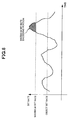
- Figure 6 is a view of a bit rate in image encoding processing in an image encoder of the present embodiment.
- a bit rate of an image gently changes about an object bit rate in accordance with the encoding difficulty.
- VBR control is performed.
- the CBR control starts functioning to control so that the bit rate does not exceed the maximum bit rate. Due to the controlling, the image encoder of the present invention is capable of maintaining picture quality almost uniform by variably controlling the bit rate in accordance with the encoding difficulty of an image while observing the maximum bit rate prescribed by the standards.
- variable bit rate processing can be realized in an application in which real-time encoding is required without largely changing the circuit configuration.
Landscapes
- Engineering & Computer Science (AREA)
- Multimedia (AREA)
- Signal Processing (AREA)
- Compression Or Coding Systems Of Tv Signals (AREA)
- Television Signal Processing For Recording (AREA)
Abstract
Description
Claims (25)
- An image encoder, comprising:a first quantizer scale setting means for setting a first quantizer scale in a first image processing unit in accordance with an input image signal so as to attain an object bit rate;a second quantizer scale setting means for setting a second quantizer scale in a second image processing unit which is shorter than said first image processing unit in accordance with said input image signal so as not to exceed a maximum bit rate prescribed in advance; andan encoding means for performing encoding processing on said input image signal by using the larger of said first and second quantizer scales.
- An image encoder as set forth in claim 1, wherein said first image processing unit is a GOP (Group Of Picture: an image group including a plurality of picture) unit.
- an image encoder as set forth in claim 1, wherein said second image processing unit is a macroblock unit.
- An image encoder, comprising:a first quantizer scale setting means for setting a first quantizer scale in a first image processing unit in accordance with an input image signal so as to attain an object bit rate;a second quantizer scale setting means for setting a second quantizer scale in a second image processing unit which is shorter than said first image processing unit in accordance with said input image signal so as not to exceed a maximum bit rate prescribed in advance;a quantizer scale selecting means for selecting the larger of said first and second quantizer scales; andan encoding means for performing encoding processing on said input image signal by using said quantizer scale selected by said quantizer scale selecting means.
- an image encoder as set forth in claim 4, wherein said first image processing unit is a GOP (Group Of Picture: an image group including a plurality of picture) unit.
- an image encoder as set forth in claim 1, wherein said second image processing unit is a macroblock unit.
- An image encoder as set forth in claim 4, wherein said first quantizer scale setting means sets an object bit amount of encoding processing in said first image processing unit.
- An image encoder as set forth in claim 4, wherein said first quantizer scale setting means sets said first quantizer scale in accordance with a remaining amount of encoding bits and a response speed in the immediately previous said first image processing unit.
- An image encoder as set forth in claim 4, comprising a memory means for storing the remaining amount of encoding bits in said first image processing unit; and wherein said first quantizer scale setting means sets an object bit amount in the next said first image processing unit in accordance with the remaining amount of encoding bits stored in said memory means.
- An image encoder as set forth in claim 4, whrein said second quantizer scale setting means sets an object bit amount in the next said second image processing unit for every said second image processing unit.
- An image encoder as set forth in claim 4, wherein said second quantizer scale setting means sets an object bit amount in the next said second image processing unit in accordance with the object bit rate and the remaining amount of encoding bits in the immediately previous said second image processing unit when instructed to encode an image by said second quantizer scale.
- An image encoder as set forth in claim 4, wherein said second quantizer scale setting means sets an object bit amount in the next said second image processing unit in accordance with the maximum bit rate and the remaining amount of encoding bits in the immediately previous said second image processing unit when instructed to encode an image by said first quantizer scale.
- An image encoder as set forth in claim 12, wherein said second quantizer scale setting means sets an object bit amount in the next said second image processing unit in accordance with the remaining amount of encoding bits and the maximum bit rate when a remaining amount of encoding bits in the immediately previous said second image processing unit is negative.
- An image encoder as set forth in claim 12, wherein said second quantizer scale setting means sets an object bit amount in the next said second image processing unit in accordance with the maximum bit rate and regardless of the remaining amount of encoding bits when a remaining amount of encoding bits in the immediately previous said second image processing unit is positive or "0".
- An image encoder as set forth in claim 4, further comprises an instruction signal for instructing to perform image encoding processing by using either one of the first quantizer scale or a second quantizer scale, and a control means for respectively outputting the object bit rate and the maximum bit rate to said first quantizer scale setting means and said second quantizer scale setting means.
- An image encoder as set forth in claim 15, wherein said control means outputs said instruction signal to said quantizer scale selecting means.
- An image encoder as set forth in claim 15, wherein said control means outputs said instruction signal to instruct to perform processing by said second quantizer scale in said first processing unit on said input image signal when instructing image encoding processing by said first quantizer scale.
- An image encoder as set forth in claim 17, wherein said control means outputs said instruction signal to instruct to switch to image encoding processing by said first quantizer scale when image encoding processing by said second quantizer scale in said first image processing unit is completed.
- An image encoding method, including the steps of:setting a first quantizer scale oin a first image processing unit in accordance with an input image signal so as to attain an object bit rate;setting a second quantizer scale in a second image processing unit which is shorter than said first image processing unit in accordance with said input image signal so as not to exceed a maximum bit rate prescribed in advance; andperforming encoding processing on said input image signal by using the larger of said first and second quantizer scales.
- An image encoder as set forth in claim 19, wherein an object bit amount in said first image processing unit is set and said first quantizer scale is set in accordance with a remaining amount of encoding bits and response speed in the immediately previous said first image processing unit when performing image encoding processing by using said first quantizer scale.
- An image encoding means as set forth in claim 19, wherein if said first quantizer scale calculated in accordance with the remaining amount of encoding bits and response speed in the immediately previous said first image processing unit is smaller than a reference value, the reference value is set as a quantizer scale in the next said first image processing unit when performing image encoding processing by using said first quantizer scale.
- An image encoding method as set forth in claim 19, wherein said first image processing unit is a GPO unit.
- An image encoding method as set forth in claim 19, wherein said second image processing unit is a macroblock unit.
- An image encoding method as set forthin claim 19, wherein:an object bit amount in the next said second image processing unit is set for each of said second image processing units when determining said second quantizer scalean object bit amount in the next said second image processing unit is set in accordance with an object bit rate and a remaining amount of encoding bits in the immediately previous said second image processing unit when instructed to perform image encoding processing by said second quantization scale; andan object bit amount in the next said first image processing unit is set in accordance with a maximum bit rate and the remaining amount of encoding bits in the immediately previous said first image processing unit if the remaining amount of encoding bits in the immediately previous said first image processing unit is negative, while, an object bit amount in the next said first image processing unit is set in accordance with said maximum bit rate regardless of the immediately previous said first image processing unit if the remaining amount of encoding bits in the immediately previous said first image processing unit when instructed to perform image encoding processing by said first quantizer scale.
- An image encoding method as set forth in claim 19, for performing image encoding processing by said second quantizer scale in said second image processing unit on said input image signal, and then, performing image encoding processing by said first quiantizer scale in accordance with a result of the encoding processing by the second quantizer scale when performing image encoding processing by said first quantizer scale
Applications Claiming Priority (3)
| Application Number | Priority Date | Filing Date | Title |
|---|---|---|---|
| JP11685599 | 1999-04-23 | ||
| JP11685599 | 1999-04-23 | ||
| PCT/JP2000/002592 WO2000065842A1 (en) | 1999-04-23 | 2000-04-20 | Image encoder and its method |
Publications (2)
| Publication Number | Publication Date |
|---|---|
| EP1091588A1 true EP1091588A1 (en) | 2001-04-11 |
| EP1091588A4 EP1091588A4 (en) | 2004-08-11 |
Family
ID=14697306
Family Applications (1)
| Application Number | Title | Priority Date | Filing Date |
|---|---|---|---|
| EP00917388A Withdrawn EP1091588A4 (en) | 1999-04-23 | 2000-04-20 | IMAGE ENCODER AND METHOD |
Country Status (4)
| Country | Link |
|---|---|
| US (1) | US6661840B1 (en) |
| EP (1) | EP1091588A4 (en) |
| JP (1) | JP4706104B2 (en) |
| WO (1) | WO2000065842A1 (en) |
Cited By (14)
| Publication number | Priority date | Publication date | Assignee | Title |
|---|---|---|---|---|
| WO2001082605A1 (en) | 2000-04-21 | 2001-11-01 | Sony Corporation | Encoding device and method, recorded medium, and program |
| EP1524860A3 (en) * | 2003-10-16 | 2005-08-24 | Nvidia Corporation | Apparatus, system, and method for video encoder rate control |
| FR2882614A1 (en) * | 2005-02-28 | 2006-09-01 | Canon Kk | Digital image signal encoding method for use in e.g. digital camera, involves determining encoding mode when level of occupancy is above preset threshold, and encoding sample based on determined encoding mode |
| EP1763250A3 (en) * | 2005-06-04 | 2009-01-21 | Samsung Electronics Co., Ltd. | Display driving apparatus and method and medium for implementing the display driving method |
| US7769084B1 (en) | 2002-07-15 | 2010-08-03 | Apple Inc. | Method for implementing a quantizer in a multimedia compression and encoding system |
| US7804897B1 (en) * | 2002-12-16 | 2010-09-28 | Apple Inc. | Method for implementing an improved quantizer in a multimedia compression and encoding system |
| ITTO20090486A1 (en) * | 2009-06-25 | 2010-12-26 | St Microelectronics Pvt Ltd | DYNAMIC CONTROLLER OF INDEPENDENT TRANSMISSION SPEED FROM THE GROUP OF IMAGES |
| US7936938B2 (en) | 2004-09-07 | 2011-05-03 | Canon Kabushiki Kaisha | Methods and devices for encoding a digital image signal and associated decoding methods and devices |
| US7940843B1 (en) | 2002-12-16 | 2011-05-10 | Apple Inc. | Method of implementing improved rate control for a multimedia compression and encoding system |
| EP2265025A4 (en) * | 2008-06-05 | 2013-01-30 | Nippon Telegraph & Telephone | VIDEO CODING QUANTITY CONTROL METHOD, VIDEO CODING QUANTITY CONTROL DEVICE, VIDEO CODING QUANTITY CONTROL PROGRAM, AND COMPUTER-READABLE RECORDING MEDIUM HAVING THE PROGRAM RECORDED THEREIN |
| US8428127B2 (en) | 2002-07-15 | 2013-04-23 | Apple Inc. | Method of performing rate control for a compression system |
| CN101715124B (en) * | 2008-10-07 | 2013-05-08 | 镇江唐桥微电子有限公司 | Single-input and multi-output video encoding system and video encoding method |
| EP2720465A1 (en) * | 2012-09-13 | 2014-04-16 | Samsung Electronics Co., Ltd | Image compression circuit |
| GB2564644A (en) * | 2017-07-12 | 2019-01-23 | Canon Kk | Method and system of encoding a data stream according to a variable bitrate mode |
Families Citing this family (7)
| Publication number | Priority date | Publication date | Assignee | Title |
|---|---|---|---|---|
| AU2002343220A1 (en) * | 2001-11-09 | 2003-05-19 | Matsushita Electric Industrial Co., Ltd. | Moving picture coding method and apparatus |
| JP4800712B2 (en) * | 2004-09-10 | 2011-10-26 | パナソニック株式会社 | Moving picture coding apparatus, moving picture coding method, and moving picture imaging apparatus |
| JP4604757B2 (en) * | 2004-10-29 | 2011-01-05 | ソニー株式会社 | Image coding apparatus and image coding method |
| JP2010288166A (en) * | 2009-06-15 | 2010-12-24 | Panasonic Corp | Video encoding apparatus, broadcast wave recording apparatus, and program |
| CN109218724B (en) * | 2017-07-06 | 2020-08-04 | 腾讯科技(深圳)有限公司 | Data encoding method and device, storage equipment and terminal equipment |
| CN112492349A (en) * | 2020-10-29 | 2021-03-12 | 广州视源电子科技股份有限公司 | Video coding control method, device, equipment and storage medium |
| US12593043B2 (en) * | 2022-11-22 | 2026-03-31 | Adeia Guides Inc. | Video compression at scene changes for low latency interactive experience |
Family Cites Families (27)
| Publication number | Priority date | Publication date | Assignee | Title |
|---|---|---|---|---|
| US4156794A (en) * | 1977-08-25 | 1979-05-29 | Ilc Data Device Corporation | Louvred handle for electronic equipment racks and the like |
| US4345845A (en) | 1981-06-19 | 1982-08-24 | International Business Machines Corporation | Drive circuit for thermal printer |
| JPH01164588A (en) | 1987-12-21 | 1989-06-28 | Rp Topla Ltd | Cutter edge |
| JPH02305083A (en) | 1989-05-18 | 1990-12-18 | Sony Corp | Method and device for encoding video signal |
| JP2516082B2 (en) * | 1990-03-19 | 1996-07-10 | 日本ビクター株式会社 | Data compression device |
| US5542008A (en) | 1990-02-28 | 1996-07-30 | Victor Company Of Japan, Ltd. | Method of and apparatus for compressing image representing signals |
| EP0444918B1 (en) | 1990-02-28 | 1996-06-05 | Victor Company Of Japan, Limited | Data compression apparatus |
| US5134476A (en) * | 1990-03-30 | 1992-07-28 | At&T Bell Laboratories | Video signal encoding with bit rate control |
| US5150208A (en) * | 1990-10-19 | 1992-09-22 | Matsushita Electric Industrial Co., Ltd. | Encoding apparatus |
| JP2834305B2 (en) | 1990-10-19 | 1998-12-09 | 松下電器産業株式会社 | Encoding device |
| EP0514663A3 (en) * | 1991-05-24 | 1993-07-14 | International Business Machines Corporation | An apparatus and method for motion video encoding employing an adaptive quantizer |
| US5144424A (en) * | 1991-10-15 | 1992-09-01 | Thomson Consumer Electronics, Inc. | Apparatus for video data quantization control |
| JP3013602B2 (en) | 1992-05-29 | 2000-02-28 | 三菱電機株式会社 | Video signal encoding device |
| US5440344A (en) * | 1992-04-28 | 1995-08-08 | Mitsubishi Denki Kabushiki Kaisha | Video encoder using adjacent pixel difference for quantizer control |
| JP2502898B2 (en) | 1992-09-28 | 1996-05-29 | 松下電器産業株式会社 | Image coding device |
| US5703646A (en) | 1993-04-09 | 1997-12-30 | Sony Corporation | Picture encoding method, picture encoding apparatus and picture recording medium |
| DE69430877T2 (en) | 1993-04-09 | 2003-02-06 | Sony Corp., Tokio/Tokyo | Image encoding method and device |
| US5654760A (en) * | 1994-03-30 | 1997-08-05 | Sony Corporation | Selection of quantization step size in accordance with predicted quantization noise |
| JPH07321664A (en) * | 1994-03-30 | 1995-12-08 | Sony Corp | Quantization control device, quantization control method, and coding device |
| JP3265818B2 (en) * | 1994-04-14 | 2002-03-18 | 松下電器産業株式会社 | Video encoding method |
| FR2728130A1 (en) * | 1994-12-13 | 1996-06-14 | Matra Communication | DEVICE FOR DIGITAL ENCODING OF VIDEO PROGRAMS |
| US5710595A (en) * | 1994-12-29 | 1998-01-20 | Lucent Technologies Inc. | Method and apparatus for controlling quantization and buffering for digital signal compression |
| US5929916A (en) * | 1995-12-26 | 1999-07-27 | Legall; Didier J. | Variable bit rate encoding |
| JPH10164588A (en) * | 1996-11-26 | 1998-06-19 | Sony Corp | Video signal encoding method, video signal encoding device, and recording medium |
| KR100227336B1 (en) * | 1997-02-20 | 1999-11-01 | 서평원 | Transmission rate control method for fixed rate MPEG video transmitter and apparatus thereof |
| JP3270388B2 (en) | 1998-03-04 | 2002-04-02 | エヌイーシービューテクノロジー株式会社 | Polarized illumination device and projection display device using the same |
| JPH11313318A (en) | 1998-04-28 | 1999-11-09 | Matsushita Electric Ind Co Ltd | Image coding method |
-
2000
- 2000-04-20 JP JP2000614665A patent/JP4706104B2/en not_active Expired - Fee Related
- 2000-04-20 EP EP00917388A patent/EP1091588A4/en not_active Withdrawn
- 2000-04-20 WO PCT/JP2000/002592 patent/WO2000065842A1/en not_active Ceased
- 2000-04-20 US US09/720,467 patent/US6661840B1/en not_active Expired - Fee Related
Cited By (27)
| Publication number | Priority date | Publication date | Assignee | Title |
|---|---|---|---|---|
| WO2001082605A1 (en) | 2000-04-21 | 2001-11-01 | Sony Corporation | Encoding device and method, recorded medium, and program |
| EP1198132A4 (en) * | 2000-04-21 | 2010-07-28 | Sony Corp | CODING METHOD AND DEVICE, RECORDING MEDIUM, AND PROGRAM |
| US10848762B2 (en) | 2002-07-15 | 2020-11-24 | Apple Inc. | Method for implementing a quantizer in a multimedia compression and encoding system |
| US10104375B2 (en) | 2002-07-15 | 2018-10-16 | Apple Inc. | Method for implementing a quantizer in a multimedia compression and encoding system |
| US9819939B2 (en) | 2002-07-15 | 2017-11-14 | Apple Inc. | Method for implementing a quantizer in a multimedia compression and encoding system |
| US9137535B2 (en) | 2002-07-15 | 2015-09-15 | Apple Inc. | Method for implementing a quantizer in a multimedia compression and encoding system |
| US8428127B2 (en) | 2002-07-15 | 2013-04-23 | Apple Inc. | Method of performing rate control for a compression system |
| US7769084B1 (en) | 2002-07-15 | 2010-08-03 | Apple Inc. | Method for implementing a quantizer in a multimedia compression and encoding system |
| US7940843B1 (en) | 2002-12-16 | 2011-05-10 | Apple Inc. | Method of implementing improved rate control for a multimedia compression and encoding system |
| US7804897B1 (en) * | 2002-12-16 | 2010-09-28 | Apple Inc. | Method for implementing an improved quantizer in a multimedia compression and encoding system |
| US8477843B2 (en) | 2002-12-16 | 2013-07-02 | Apple Inc. | Method of implementing improved rate control for a multimedia compression and encoding system |
| US7535959B2 (en) | 2003-10-16 | 2009-05-19 | Nvidia Corporation | Apparatus, system, and method for video encoder rate control |
| EP1524860A3 (en) * | 2003-10-16 | 2005-08-24 | Nvidia Corporation | Apparatus, system, and method for video encoder rate control |
| EP1912442A3 (en) * | 2003-10-16 | 2009-08-12 | Nvidia Corporation | Apparatus, system, and method for video encoder rate control |
| US7936938B2 (en) | 2004-09-07 | 2011-05-03 | Canon Kabushiki Kaisha | Methods and devices for encoding a digital image signal and associated decoding methods and devices |
| FR2882614A1 (en) * | 2005-02-28 | 2006-09-01 | Canon Kk | Digital image signal encoding method for use in e.g. digital camera, involves determining encoding mode when level of occupancy is above preset threshold, and encoding sample based on determined encoding mode |
| US7860322B2 (en) | 2005-06-04 | 2010-12-28 | Samsung Electronics Co., Ltd. | Display driving apparatus and method and medium for implementing the display driving method |
| EP1763250A3 (en) * | 2005-06-04 | 2009-01-21 | Samsung Electronics Co., Ltd. | Display driving apparatus and method and medium for implementing the display driving method |
| US8548042B2 (en) | 2008-06-05 | 2013-10-01 | Nippon Telegraph And Telephone Corporation | Video bitrate control method, video bitrate control apparatus, video bitrate control program, and computer-readable recording medium having the program recorded thereon |
| EP2265025A4 (en) * | 2008-06-05 | 2013-01-30 | Nippon Telegraph & Telephone | VIDEO CODING QUANTITY CONTROL METHOD, VIDEO CODING QUANTITY CONTROL DEVICE, VIDEO CODING QUANTITY CONTROL PROGRAM, AND COMPUTER-READABLE RECORDING MEDIUM HAVING THE PROGRAM RECORDED THEREIN |
| CN101715124B (en) * | 2008-10-07 | 2013-05-08 | 镇江唐桥微电子有限公司 | Single-input and multi-output video encoding system and video encoding method |
| US8913658B2 (en) | 2009-06-25 | 2014-12-16 | Stmicroelectronics International N.V. | GOP-independent dynamic bit-rate controller |
| US9497464B2 (en) | 2009-06-25 | 2016-11-15 | Stmicroelectronics International N.V. | GOP-independent dynamic bit-rate controller |
| ITTO20090486A1 (en) * | 2009-06-25 | 2010-12-26 | St Microelectronics Pvt Ltd | DYNAMIC CONTROLLER OF INDEPENDENT TRANSMISSION SPEED FROM THE GROUP OF IMAGES |
| EP2720465A1 (en) * | 2012-09-13 | 2014-04-16 | Samsung Electronics Co., Ltd | Image compression circuit |
| GB2564644A (en) * | 2017-07-12 | 2019-01-23 | Canon Kk | Method and system of encoding a data stream according to a variable bitrate mode |
| GB2564644B (en) * | 2017-07-12 | 2020-12-16 | Canon Kk | Method and system of encoding a data stream according to a variable bitrate mode |
Also Published As
| Publication number | Publication date |
|---|---|
| JP4706104B2 (en) | 2011-06-22 |
| WO2000065842A1 (en) | 2000-11-02 |
| EP1091588A4 (en) | 2004-08-11 |
| US6661840B1 (en) | 2003-12-09 |
Similar Documents
| Publication | Publication Date | Title |
|---|---|---|
| US6661840B1 (en) | Image encoder and method of the same | |
| US6907069B2 (en) | Picture coding apparatus, picture coding method, and recording medium having picture coding program recorded thereon | |
| KR100343352B1 (en) | Two-pass encoding method of digital motion video sequences for constant-or variable bit rate | |
| EP0689360B1 (en) | Variable transfer rate video coding apparatus and method | |
| EP1372113B1 (en) | Variable bit rate video encoding method and device | |
| US6337879B1 (en) | Video data compression apparatus and method of same | |
| JP3864461B2 (en) | Video data compression apparatus and method | |
| US6823008B2 (en) | Video bitrate control method and device for digital video recording | |
| EP1515563A2 (en) | Systems and methods for selecting a macroblock mode in a video encoder | |
| US6229849B1 (en) | Coding device and method | |
| US6928113B1 (en) | Encoding apparatus and method | |
| JPWO2000065842A1 (en) | Image encoding device and method | |
| US20080025392A1 (en) | Method and apparatus for controlling video encoding data rate | |
| US8116577B2 (en) | Encoding method, encoding device, encoding process program, and recording medium on which encoding process program is recorded | |
| US20100002765A1 (en) | Image encoding apparatus and method | |
| US6226326B1 (en) | Coding device and coding method | |
| US7801214B2 (en) | Method and apparatus for controlling encoding rate and quantization scales | |
| US7606433B2 (en) | Encoding apparatus, encoding method, and storage medium | |
| EP1089569A1 (en) | Image encoding device and its method | |
| JP3937248B2 (en) | Video signal encoding method and video signal encoding apparatus | |
| JP4604757B2 (en) | Image coding apparatus and image coding method | |
| JP3765129B2 (en) | Encoding apparatus and encoding method | |
| JP2007116655A (en) | Moving picture coding apparatus | |
| JP4404232B2 (en) | Quantization method, quantization apparatus, quantization step determination method, and quantization step determination apparatus | |
| EP1944980A2 (en) | Bit rate control algorithm |
Legal Events
| Date | Code | Title | Description |
|---|---|---|---|
| PUAI | Public reference made under article 153(3) epc to a published international application that has entered the european phase |
Free format text: ORIGINAL CODE: 0009012 |
|
| 17P | Request for examination filed |
Effective date: 20010104 |
|
| AK | Designated contracting states |
Kind code of ref document: A1 Designated state(s): AT BE CH CY DE DK ES FI FR GB GR IE IT LI LU MC NL PT SE |
|
| RBV | Designated contracting states (corrected) |
Designated state(s): DE FR GB |
|
| A4 | Supplementary search report drawn up and despatched |
Effective date: 20040624 |
|
| RIC1 | Information provided on ipc code assigned before grant |
Ipc: 7H 04N 7/26 B Ipc: 7H 04N 7/30 A |
|
| 17Q | First examination report despatched |
Effective date: 20050316 |
|
| STAA | Information on the status of an ep patent application or granted ep patent |
Free format text: STATUS: THE APPLICATION IS DEEMED TO BE WITHDRAWN |
|
| 18D | Application deemed to be withdrawn |
Effective date: 20151103 |