EP1090859A1 - Apparatus for removing sheets one by one from the top of a stack of sheets - Google Patents
Apparatus for removing sheets one by one from the top of a stack of sheets Download PDFInfo
- Publication number
- EP1090859A1 EP1090859A1 EP00203321A EP00203321A EP1090859A1 EP 1090859 A1 EP1090859 A1 EP 1090859A1 EP 00203321 A EP00203321 A EP 00203321A EP 00203321 A EP00203321 A EP 00203321A EP 1090859 A1 EP1090859 A1 EP 1090859A1
- Authority
- EP
- European Patent Office
- Prior art keywords
- sheets
- stack
- blowing
- removal
- air flow
- Prior art date
- Legal status (The legal status is an assumption and is not a legal conclusion. Google has not performed a legal analysis and makes no representation as to the accuracy of the status listed.)
- Granted
Links
- 238000007664 blowing Methods 0.000 claims abstract description 74
- 230000001154 acute effect Effects 0.000 claims 1
- 238000005192 partition Methods 0.000 description 8
- 230000000694 effects Effects 0.000 description 6
- 230000003213 activating effect Effects 0.000 description 2
- 238000010586 diagram Methods 0.000 description 2
- 230000007704 transition Effects 0.000 description 2
- 230000004913 activation Effects 0.000 description 1
- 230000007257 malfunction Effects 0.000 description 1
- 230000000284 resting effect Effects 0.000 description 1
- 230000000717 retained effect Effects 0.000 description 1
- 238000007789 sealing Methods 0.000 description 1
- 238000000926 separation method Methods 0.000 description 1
- 238000007666 vacuum forming Methods 0.000 description 1
Images




Classifications
-
- B—PERFORMING OPERATIONS; TRANSPORTING
- B65—CONVEYING; PACKING; STORING; HANDLING THIN OR FILAMENTARY MATERIAL
- B65H—HANDLING THIN OR FILAMENTARY MATERIAL, e.g. SHEETS, WEBS, CABLES
- B65H3/00—Separating articles from piles
- B65H3/08—Separating articles from piles using pneumatic force
- B65H3/12—Suction bands, belts, or tables moving relatively to the pile
- B65H3/124—Suction bands or belts
- B65H3/128—Suction bands or belts separating from the top of pile
-
- B—PERFORMING OPERATIONS; TRANSPORTING
- B65—CONVEYING; PACKING; STORING; HANDLING THIN OR FILAMENTARY MATERIAL
- B65H—HANDLING THIN OR FILAMENTARY MATERIAL, e.g. SHEETS, WEBS, CABLES
- B65H3/00—Separating articles from piles
- B65H3/46—Supplementary devices or measures to assist separation or prevent double feed
- B65H3/48—Air blast acting on edges of, or under, articles
Definitions
- the invention relates to apparatus for removing sheets one by one in a removal direction from the top of a stack of sheets, comprising a support for the stack of sheets, removal means disposed a short distance above the stack for attracting and removing in the removal direction the top sheet of a stack of sheets lying on the support, and side blowing means for blowing air, looking in the removal direction of the sheets, from the side in the direction of the stack.
- feed faults particularly the feed of double sheets or the failure of sheet feed
- time elapsing between two feed faults in high-speed machines can be made acceptably short.
- One and the same malfunction frequency number of faults per total number of feed cycles
- the side blowing means can generate at least two differently directed air flows, a first air flow substantially parallel to the plane in which the sheets are lying and at least directed on the top sheets of the stack and the space thereabove, and a second air flow which, with respect to the first air flow, is directed obliquely upwards in the direction of a sheet attracted by the removal means.
- the blowing means can occupy a fixed orientation with respect to the stack, by accommodating them in a slidable side guide, so that the operation is independent of the sheet format.
- front blowing means are provided to blow air in a direction opposed to the removal direction between a sheet attracted by the removal means and the rest of the stack.
- air can readily be blown into the space beneath the top sheet as created by the side blowing means, so that sheets situated beneath the top sheet can be pressed down in order to retain the same on removal of the top sheet.
- the side blowing means can also generate at least a third air flow, directed on sheets situated beneath the top sheets of the stack.
- the effect of this is that sheets which cannot easily be blown loose and lifted by the first air flow, for example because they are too heavy and/or curved with the convex side lying at the top on the support, are brought within range of the first air flow and the attracting action of the removal means.
- the apparatus shown in Fig. 1 for loosening and removing the top sheet from a stack of sheets 1 is adapted to feed receiving sheets one by one from a supply container to a printing apparatus (not shown) in which said receiving sheets can be printed.
- the apparatus shown comprises a suction belt conveyor 2 disposed above the stack of sheets 1 and consisting of a fixed suction box 3 with an endless conveyor belt 4 trained therearound.
- the bottom of the suction box 3 and the conveyor belt 4 are both formed with holes. Air passages form at places where the holes come to be opposite one another, so that an upwardly directed force can be obtained as shown by arrows 7 in Fig. 1.
- This upwardly directed force 7 is generated by means of a fan 8 connected via a suction line 9 to the suction box 3.
- the upwardly directed force 7 is brought about to suck the top sheet of the stack 1 against the suction belt conveyor 4 by activating a magnetic valve 10 in the suction line 9, said magnetic valve being adapted to be operated by a control system (not shown).
- the sheet released from the stack and attracted by suction is then removed from the stack 1 by the conveyor belt 4 being driven.
- On transfer of said sheet to a transport nip (not shown) in the removal path the drive for the endless conveyor belt 4 is stopped and the vacuum in the suction box 3 is switched off.
- a delivery line 11 is connected to the delivery side of the fan 12 and discharges at one side of the stack of sheets 1.
- the fan 12 blows air into the delivery line 11. This air flows out in the direction of the side of the stack of sheets 1 to blow the top sheets loose and push the top sheet up in the direction of the suction belt conveyor 2 as will be described in greater detail hereinafter with reference to Figs. 3 - 5.
- a fan 13 also feeds air via a line 14 to a blowing nozzle 15 from which it is blown against the front of the top sheets released from the stack.
- This air flow 16 blown against the front of the stack thus serves to support the loosening of only the top sheet of the stack by creating a positive pressure between the top sheet and the rest of the stack, such positive pressure pressing firmly on the stack those sheets which are situated beneath the top sheet in order to prevent their removal.
- An insert 17 shown in detail in Figs. 4A and 4B in the opening of the delivery line 11 ensures that the side-blowing air is divided up into a number of different air flows each having its own specific function to enable the top sheet to be properly separated from a stack of sheets.
- the insert 17 acts as a nozzle in the form of a spout mounted slidably in the opening of the delivery line 11 in order that the insert 17 for separating sheets of different formats, e.g. varying between A5 and A3, can be placed at substantially equal distances from the side of the stack.
- the air flowing out of the delivery line 11 has a high speed, e.g. an exit speed of as much as 22 to 28 m/s.
- the blowing nozzles formed by the insert 17 comprise:
- the exit openings 18 to 23 inclusive are formed in the rectangular cross-section of the insert.
- the insert 17 contains two vertical partitions 25 and 26 which, looking from the sheet removal side, are disposed respectively at a distance of 1/3 and 5/6 parts of the width of the insert.
- the partitions form three compartments 27, 28 and 29 in the size of 1/3, 1/2 and 5/6 parts of the cross-section of the delivery line 11.
- compartment 29 at the half adjoining partition 26 is provided with a block 30 in a height of 1/3 of the partition in order to form thereabove an outflow opening 20 and therebeneath an outflow opening 22.
- blocks 31 and 32 are disposed respectively at top and bottom, each in a height of 1/3 of the partition height, to form outflow opening 19.
- Block 30 has an oblique side extending from an edge forming the outflow opening 19 to the partition 26
- block 32 has an oblique top extending from the bottom edge of outflow opening 19 to the bottom wall of the insert 17
- block 31 has a bottom and side each forming a continuous transition from the outside of the insert 17 and respectively the top edge of outflow opening 31 and the side edge of outflow opening 20.
- the compartment 27 is provided with blocks 33 and 34 respectively, each of a height of 1/3 of the partition height, to form outflow opening 18.
- a plate 35 is disposed between the partitions 25 and 26 at a angle of about 40° to the longitudinal direction of the insert.
- Plate 35 extends to outside the outflow plane of the openings 18 and 22 and forms a wide outflow opening 23 at the top of the insert 17 with a height of about 1/5 parts of the height of the insert 17.
- Beneath the oblique plate 35 a block 36 seals off the insert 17 leaving a square outflow opening 21 situated next to outflow opening 22 and of a somewhat smaller height.
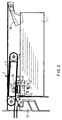
- Figs. 3 and 4 show the blowing nozzle 15 which blows an air flow 16 against the front of sheets released from the stack in order to bring air between the sheet sucked against the suction conveyor belt 4 and a sheet therebeneath, in order to press the latter sheet on the stack.
- the air flow 16 is directed in the form of a knife over an area situated just in front of the front edge of a sheet sucked against the suction conveyor belt 4 and is embodied by a slot-shaped blowing spout 37 which in a central part 37' is wider than at parts 37'' situated next to the same, in order thus to give a greater air flow in the central part than at the sides, in order to obtain a good build-up of air pressure beneath the top sheet.
- suction conveyor belt 4 diverging in the sheet removal direction with respect to the stack of sheets and by two contact-pressure elements 38 resting on the back of the stack, said elements 38, looking in the sheet removal direction, keeping the sides of the top sheet down in order to prevent air from escaping from the blowing spout at the sides of the stack before sufficient air pressure has built up beneath the top sheet.
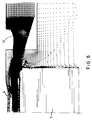
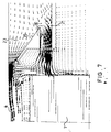
- Figs. 6 - 8 show the air flow from the side blowing means in different cross-sections.
- the air speed in Figs. 6 - 8 is shown at different places, higher air speeds being indicated by larger arrow heads. In areas with a considerable flow at high speeds the large arrow heads close together give a greater blackening than in areas having a low flow at low speed, as will be particularly apparent from Fig. 6.
- the sheets forming a stack are situated tightly on one another. Because of the resistance that the incoming air experiences between the sheets, in this starting situation it is practically impossible to suck up a sheet simply by activating the suction action of the suction conveyor means above the stack. On an upward movement of the sheets there is in fact a vacuum forming between the sheets and this vacuum increases with increasing upward speed of the sheets. By blowing air between the sheets this vacuum force is eliminated. This blowing loose starts before the suction effect of the suction conveyor means is activated and is achieved particularly by air flow from side blowing nozzles 18 and 19. The powerful somewhat upwardly directed air flow from nozzle 19 shown in Fig.
- blowing nozzle 19 is provided with a lowered part 19' as shown in Fig. 3, which ensures that when the top sheet is situated at the transition between blowing nozzles 22 and 19 said sheet rises satisfactorily.
- the flat airstream directed obliquely upwards from blowing nozzle 23 is directed at the side of a sheet sucked against the suction belt 4, as shown particularly in Fig. 8 and also in Fig. 7.
- the instability occurring in the case of sheets along which air flows is known as the Kelvin-Helmholtz effect. Any sheets that might still be sticking to one another are separated as a result of this effect during the last part where sheets are lifted from the stack to the suction belt. Smooth sheets particularly in a damp environment are sensitive to sticking together.
- the suction nozzle In order to hold the top sheet against the suction belt conveyor within the range of the side blowing means, the suction nozzle has, on one side projecting outside the suction belt, contact-suction openings to prevent the top sheet from hanging down in the range of operation of the side blowing means. The top air flow shown in Figs.
- a condition for sheets being properly blown loose is that the side edges of the sheets which are required to be blown loose should be situated straight above one another. This is achieved by holding against a stop the top sheets of the stack on the side opposite the side blowing means, such stop preventing a sheet from being blown away sideways.
- the air flow 16 from front blowing means 15 is activated in order to blow air between the top sheet sucked against the suction belt 4 and the rest of the stack in order to form a positive air pressure into the space formed by the side blowing means, namely the air flow from side blowing nozzle 23, to press the stack down.
- suction conveyor belt 4 is started in order to remove the sheet sucked into contact, the air pressure that has built up beneath said sheet pressing the rest of the stack down in order to prevent following sheets from being simultaneously entrained with the sheet requiring to be removed.
- the above-described apparatus can advantageously be used in the apparatus described in Applicants' European Patent Application 0 801 016, the side blowing means indicated therein being constructed as described above.
Landscapes
- Engineering & Computer Science (AREA)
- Mechanical Engineering (AREA)
- Sheets, Magazines, And Separation Thereof (AREA)
Abstract
Front blowing means (15) then blow air between the sheet to be removed by the suction conveyor means (3, 4) and the rest of the stack (1) in order to press any following sheets firmly on to the rest of the stack.
Description
- The invention relates to apparatus for removing sheets one by one in a removal direction from the top of a stack of sheets, comprising a support for the stack of sheets, removal means disposed a short distance above the stack for attracting and removing in the removal direction the top sheet of a stack of sheets lying on the support, and side blowing means for blowing air, looking in the removal direction of the sheets, from the side in the direction of the stack.
- An apparatus of this kind is known from US
Patent 4 787 618. This describes an apparatus wherein the removal means comprise a suction means against which the top sheet of the stack is firmly sucked so as to be removed on transport by said suction means, and wherein in addition the side blowing means introduce air into the stack of sheets in the event of sheets sticking to one another and in the event of the top sheet not coming into contact with the suction means at the correct time.
The range of sheets used as receiving material in the current generation of printing machines is considerable and it is expected that it will increase even more in future. In these conditions, a reliable supply of this broad range of receiving materials, varying from thin to thick receiving material and from smooth to stiff receiving material, is subject to increasingly stringent requirements. Especially in the case of fast productive printing machines, it is desirable to minimise feed faults, particularly the feed of double sheets or the failure of sheet feed, in order that the time elapsing between two feed faults in high-speed machines can be made acceptably short. One and the same malfunction frequency (number of faults per total number of feed cycles) will occur, for example, just once a day in the case of a slow and less productive printing machine, but, for example, once per hour in the case of a high-speed productive printing machine, the latter being unacceptable. - In order to obtain good separation between just the top sheet of a stack and the rest of the stack it is known, from European Patent Application 0 223 502, to direct a number of differently directed air jets on to the front of the stack of sheets in a direction which is opposed to the direction in which the sheets are removed from the stack one by one. These air jets serve to blow the top sheets of the stack loose from one another and move them upwards in the direction of a suction conveyor belt disposed above the stack and in order to create a positive pressure in the area between the top sheet sucked against the suction conveyor belt and the rest of the stack to ensure that on the removal of the top sheet by the suction conveyor belt the following sheets of the stack are retained by pressing them down. One disadvantage of this latter known apparatus is that, necessarily, the transport path
provided at the front of the stack for the removal of the top sheet, as considered in height, limits the space for providing the blowing means. The blowing means must in fact be disposed at an ample distance beneath the suction conveyor belt to offer sufficient free access between the belt and the blowing means for the undisturbed removal of sheets from the stack. This limits the freedom for achieving optimal blowing geometry. - The object of the invention is to provide an apparatus according to the preamble without the said disadvantages.
To this end, according to the invention, the side blowing means can generate at least two differently directed air flows, a first air flow substantially parallel to the plane in which the sheets are lying and at least directed on the top sheets of the stack and the space thereabove, and a second air flow which, with respect to the first air flow, is directed obliquely upwards in the direction of a sheet attracted by the removal means. As a result, when the top sheets of the stack which have been blown loose and brought up by the first air flow have come into the range of the suction conveyor belt, the sheet situated beneath the top sheet attracted by the suction conveyor belt is effectively loosened from said top sheet because of the creation of a flat air stream beneath the attracted sheet which, comparable to the fluttering of a flag in the wind, shakes any attached sheet loose. Another effect is that the blowing means can occupy a fixed orientation with respect to the stack, by accommodating them in a slidable side guide, so that the operation is independent of the sheet format. - Preferably, front blowing means are provided to blow air in a direction opposed to the removal direction between a sheet attracted by the removal means and the rest of the stack. As a result, air can readily be blown into the space beneath the top sheet as created by the side blowing means, so that sheets situated beneath the top sheet can be pressed down in order to retain the same on removal of the top sheet.
- The side blowing means can also generate at least a third air flow, directed on sheets situated beneath the top sheets of the stack. The effect of this is that sheets which cannot easily be blown loose and lifted by the first air flow, for example because they are too heavy and/or curved with the convex side lying at the top on the support, are brought within range of the first air flow and the attracting action of the removal means.
The invention will hereinafter be explained with reference to the accompanying drawings wherein: - Fig. 1 is a diagram of an apparatus in which the invention can be applied,
- Fig. 2 is a top view of the apparatus shown in Fig. 1,
- Fig. 3 is a side elevation of an apparatus according to the invention showing the placing of the air separating means with respect to a stack of sheets,
- Fig. 4 is a top view of the apparatus shown in Fig. 3,
- Figs. 5A and 5B are different views in perspective of an insert suitable for generating the different air flows by side blowing means, and
- Figs. 6, 7 and 8 are diagrams showing the air flows generated by the side blowing means respectively in the cross-sectional planes VI-VI, VII-VII and VIII-VIII shown in Fig. 3.
-
- The apparatus shown in Fig. 1 for loosening and removing the top sheet from a stack of
sheets 1 is adapted to feed receiving sheets one by one from a supply container to a printing apparatus (not shown) in which said receiving sheets can be printed. The apparatus shown comprises asuction belt conveyor 2 disposed above the stack ofsheets 1 and consisting of a fixedsuction box 3 with anendless conveyor belt 4 trained therearound. The bottom of thesuction box 3 and theconveyor belt 4 are both formed with holes. Air passages form at places where the holes come to be opposite one another, so that an upwardly directed force can be obtained as shown by arrows 7 in Fig. 1. This upwardly directed force 7 is generated by means of afan 8 connected via asuction line 9 to thesuction box 3. With thefan 8 in rotation, the upwardly directed force 7 is brought about to suck the top sheet of thestack 1 against thesuction belt conveyor 4 by activating amagnetic valve 10 in thesuction line 9, said magnetic valve being adapted to be operated by a control system (not shown). The sheet released from the stack and attracted by suction is then removed from thestack 1 by theconveyor belt 4 being driven. On transfer of said sheet to a transport nip (not shown) in the removal path the drive for theendless conveyor belt 4 is stopped and the vacuum in thesuction box 3 is switched off.
A delivery line 11 is connected to the delivery side of thefan 12 and discharges at one side of the stack ofsheets 1. If the top sheet of the stack has still not been sucked against the suction belt conveyor, thefan 12 blows air into the delivery line 11. This air flows out in the direction of the side of the stack ofsheets 1 to blow the top sheets loose and push the top sheet up in the direction of thesuction belt conveyor 2 as will be described in greater detail hereinafter with reference to Figs. 3 - 5. During the blowing loose of the top sheets from one side of the stack the incoming air forms a nucleus for blowing air between the sheets for the purpose of separating the same.
Afan 13 also feeds air via aline 14 to a blowingnozzle 15 from which it is blown against the front of the top sheets released from the stack. Thisair flow 16 blown against the front of the stack thus serves to support the loosening of only the top sheet of the stack by creating a positive pressure between the top sheet and the rest of the stack, such positive pressure pressing firmly on the stack those sheets which are situated beneath the top sheet in order to prevent their removal. - An
insert 17 shown in detail in Figs. 4A and 4B in the opening of the delivery line 11 ensures that the side-blowing air is divided up into a number of different air flows each having its own specific function to enable the top sheet to be properly separated from a stack of sheets. Theinsert 17 acts as a nozzle in the form of a spout mounted slidably in the opening of the delivery line 11 in order that theinsert 17 for separating sheets of different formats, e.g. varying between A5 and A3, can be placed at substantially equal distances from the side of the stack. The air flowing out of the delivery line 11 has a high speed, e.g. an exit speed of as much as 22 to 28 m/s.
The blowing nozzles formed by theinsert 17 comprise: - two blowing
nozzles stack 1. For this purpose thenozzles - A blowing
nozzle 20 disposed at a higher level than the blowingnozzles nozzles suction conveyor belt 4. - Two blowing
nozzles nozzles - An obliquely upwardly directed blowing
nozzle 23 to blow loose one or more sheets which may stick to the top sheet adhering to thesuction conveyor belt 4. - As shown in greater detail in Figs. 5A and 5B, the
exit openings 18 to 23 inclusive are formed in the rectangular cross-section of the insert. To this end, theinsert 17 contains twovertical partitions compartments
At mid height,compartment 29 at thehalf adjoining partition 26 is provided with ablock 30 in a height of 1/3 of the partition in order to form thereabove anoutflow opening 20 and therebeneath anoutflow opening 22. In the other half ofcompartment 29,blocks outflow opening 19.
Block 30 has an oblique side extending from an edge forming theoutflow opening 19 to thepartition 26,block 32 has an oblique top extending from the bottom edge of outflow opening 19 to the bottom wall of theinsert 17 andblock 31 has a bottom and side each forming a continuous transition from the outside of theinsert 17 and respectively the top edge of outflow opening 31 and the side edge of outflow opening 20.
At the top and bottom thecompartment 27 is provided withblocks outflow opening 18. Aplate 35 is disposed between thepartitions Plate 35 extends to outside the outflow plane of theopenings insert 17 with a height of about 1/5 parts of the height of theinsert 17. Beneath the oblique plate 35 a block 36 seals off theinsert 17 leaving a square outflow opening 21 situated next to outflow opening 22 and of a somewhat smaller height.
Figs. 3 and 4 show the blowingnozzle 15 which blows anair flow 16 against the front of sheets released from the stack in order to bring air between the sheet sucked against thesuction conveyor belt 4 and a sheet therebeneath, in order to press the latter sheet on the stack. Theair flow 16 is directed in the form of a knife over an area situated just in front of the front edge of a sheet sucked against thesuction conveyor belt 4 and is embodied by a slot-shaped blowingspout 37 which in a central part 37' is wider than at parts 37'' situated next to the same, in order thus to give a greater air flow in the central part than at the sides, in order to obtain a good build-up of air pressure beneath the top sheet. This build-up is further enhanced by thesuction conveyor belt 4 diverging in the sheet removal direction with respect to the stack of sheets and by two contact-pressure elements 38 resting on the back of the stack, saidelements 38, looking in the sheet removal direction, keeping the sides of the top sheet down in order to prevent air from escaping from the blowing spout at the sides of the stack before sufficient air pressure has built up beneath the top sheet. - The operation of the apparatus described above for separating sheets, and particularly the operation of the side blowing means, is explained further hereinafter with reference to Figs. 6 - 8, which show the air flow from the side blowing means in different cross-sections. According to an air flow model, the air speed in Figs. 6 - 8 is shown at different places, higher air speeds being indicated by larger arrow heads. In areas with a considerable flow at high speeds the large arrow heads close together give a greater blackening than in areas having a low flow at low speed, as will be particularly apparent from Fig. 6.
- At the start of a separating cycle, the sheets forming a stack are situated tightly on one another. Because of the resistance that the incoming air experiences between the sheets, in this starting situation it is practically impossible to suck up a sheet simply by activating the suction action of the suction conveyor means above the stack. On an upward movement of the sheets there is in fact a vacuum forming between the sheets and this vacuum increases with increasing upward speed of the sheets. By blowing air between the sheets this vacuum force is eliminated. This blowing loose starts before the suction effect of the suction conveyor means is activated and is achieved particularly by air flow from
side blowing nozzles nozzle 19 shown in Fig. 6 ensures that sheets which in the first instance have been blown loose bynozzle 18 which blows directly against the top sheets of the stack, are conveyed further upwards. The air flow from blowingnozzle 20 feeds upwardly moved sheets further upwards as far as thesuction belt conveyor 2 which sucks up the top sheet. As soon as the blowing loose or upward feeding stops, the stack collapses back. Just before that happens the suction action of thesuction conveyor belt 4 which is still stationary is activated to prevent the top sheet from collapsing back with the stack.
As already stated, the blowing up, particularly of heavy sheets and/or sheets which are lying curved in the stack with their convex side above, is promoted by blowing air from blowingnozzles nozzle 19 is provided with a lowered part 19' as shown in Fig. 3, which ensures that when the top sheet is situated at the transition between blowingnozzles
The flat airstream directed obliquely upwards from blowingnozzle 23 is directed at the side of a sheet sucked against thesuction belt 4, as shown particularly in Fig. 8 and also in Fig. 7. By the generation of this powerful air flow, which particularly sweeps along the bottom of the sheet sucked into contact, the top sheets flutter in a manner comparable to a flag fluttering in the wind. The instability occurring in the case of sheets along which air flows is known as the Kelvin-Helmholtz effect. Any sheets that might still be sticking to one another are separated as a result of this effect during the last part where sheets are lifted from the stack to the suction belt. Smooth sheets particularly in a damp environment are sensitive to sticking together. In order to hold the top sheet against the suction belt conveyor within the range of the side blowing means, the suction nozzle has, on one side projecting outside the suction belt, contact-suction openings to prevent the top sheet from hanging down in the range of operation of the side blowing means.
The top air flow shown in Figs. 7 and 8 is also intended to prevent sheets from being pressed against one another against the underside of the suction box as a result of the bottom air flow in shown in Fig. 7. An air flow of uniform air velocity forms as a result of the considerable restriction of the outflow opening and the shape of the inflow duct. - A condition for sheets being properly blown loose is that the side edges of the sheets which are required to be blown loose should be situated straight above one another. This is achieved by holding against a stop the top sheets of the stack on the side opposite the side blowing means, such stop preventing a sheet from being blown away sideways.
- Simultaneously with the activation of the suction effect of the
suction belt conveyor 2, theair flow 16 from front blowing means 15 is activated in order to blow air between the top sheet sucked against thesuction belt 4 and the rest of the stack in order to form a positive air pressure into the space formed by the side blowing means, namely the air flow fromside blowing nozzle 23, to press the stack down.
When this force for pressing the stack down has been built up sufficiently, with the assistance of the contact pressure means 38 sealing off the excess pressure space at the sides,suction conveyor belt 4 is started in order to remove the sheet sucked into contact, the air pressure that has built up beneath said sheet pressing the rest of the stack down in order to prevent following sheets from being simultaneously entrained with the sheet requiring to be removed.
The above-described apparatus can advantageously be used in the apparatus described in Applicants' European Patent Application 0 801 016, the side blowing means indicated therein being constructed as described above.
Claims (12)
- Apparatus for removing sheets one by one in a removal direction from the top of a stack of sheets (1), comprising a support for the stack of sheets (1), removal means (2, 3, 4) disposed a short distance above the stack for attracting and removing in the removal direction the top sheet of a stack (1) of sheets lying on the support, and side blowing means (11, 17) for blowing air, looking in the removal direction of the sheets, from the side in the direction of the stack (1), characterised in that the side blowing means (11, 17) can generate at least two differently directed air flows, a first air flow (18, 19) substantially parallel to the plane in which the sheets are lying and at least directed on the top sheets of the stack and the space thereabove, and a second air flow (23) which, with respect to the first air flow, is directed obliquely upwards in the direction of a sheet attracted by the removal means.
- Apparatus according to claim 1, characterised in that the side blowing means generating the first air flow comprise at least two spaced apart first blowing nozzles (18, 19) which each lie partially beneath the top of the stack of sheets (1) and partially above the top of the stack of sheets (1).
- Apparatus according to claim 2, characterised in that the side blowing means generating the first air flow comprise a second blowing nozzle (20) which is situated above one of the first blowing nozzles (18, 19).
- Apparatus according to any one of claims 1 to 3, characterised in that the side blowing means generating the second air flow comprise a blowing nozzle (23) which is situated at the level of the bottom of the removal means (2, 3, 4) disposed at some distance above the stack of sheets (1).
- Apparatus according to claim 4, characterised in that the third blowing nozzle (23) has a bottom surface (35) which forms an acute angle with the support for the stack of sheets (1) in order to produce an air flow from the third blowing nozzle (23) which sweeps closely along the bottom of the removal means (2, 3, 4).
- Apparatus according to claims 4 and 5, characterised in that the third blowing nozzle (23) has an outflow opening the width of which is at least twice as large as its height.
- Apparatus according to claims 2 and 4, characterised in that the third blowing nozzle (23), looking in the horizontal direction, is situated between the first two blowing nozzles (18, 19).
- Apparatus according to claim 1, characterised in that front blowing means (15) are provided for blowing air in a direction opposed to the removal direction between a sheet attracted by the removal means (2, 3, 4) and the rest of the stack (1).
- Apparatus according to claim 1, characterised in that the side blowing means (11, 17) generate at least a third air flow (21, 22) directed at sheets situated beneath the top sheets of the stack.
- Apparatus according to any one of the preceding claims, characterised in that the removal means (2) comprise a suction conveyor means (3, 4) and in that control means are provided with stop the action of the side blowing means (11, 17) shortly after the operation of the suction conveyor means (2, 3) has started.
- Apparatus according to claims 8 and 10, characterised in that the control means start the operation of the front blowing means (15) substantially simultaneously with the operation of the removal means (2, 3, 4).
- Apparatus according to claim 1, characterised in that the side blowing means (11, 17), looking in the removal direction, are situated at a short distance from the removal side of the stack of sheets (1).
Applications Claiming Priority (2)
| Application Number | Priority Date | Filing Date | Title |
|---|---|---|---|
| NL1013218 | 1999-10-05 | ||
| NL1013218A NL1013218C2 (en) | 1999-10-05 | 1999-10-05 | Device for one sheet removal from the top of a stack of sheets. |
Publications (2)
| Publication Number | Publication Date |
|---|---|
| EP1090859A1 true EP1090859A1 (en) | 2001-04-11 |
| EP1090859B1 EP1090859B1 (en) | 2003-05-21 |
Family
ID=19769996
Family Applications (1)
| Application Number | Title | Priority Date | Filing Date |
|---|---|---|---|
| EP00203321A Expired - Lifetime EP1090859B1 (en) | 1999-10-05 | 2000-09-26 | Apparatus for removing sheets one by one from the top of a stack of sheets |
Country Status (6)
| Country | Link |
|---|---|
| US (1) | US6431538B1 (en) |
| EP (1) | EP1090859B1 (en) |
| JP (1) | JP4712174B2 (en) |
| DE (1) | DE60002811T2 (en) |
| NL (1) | NL1013218C2 (en) |
| TW (1) | TW469256B (en) |
Cited By (5)
| Publication number | Priority date | Publication date | Assignee | Title |
|---|---|---|---|---|
| DE10250146A1 (en) * | 2002-10-28 | 2004-05-13 | OCé PRINTING SYSTEMS GMBH | Single sheet feeder for a printer |
| DE10250149A1 (en) * | 2002-10-28 | 2004-05-13 | OCé PRINTING SYSTEMS GMBH | Sheet feeder for printer, directs airstream to stack of sheets and has rest plates which rest on uppermost sheet to compensate for force acting against conveying direction |
| EP1820760A1 (en) | 2006-02-21 | 2007-08-22 | Canon Kabushiki Kaisha | Apparatus for separating sheets from a pile comprising blowing means to assist separation |
| EP2119652A3 (en) * | 2007-05-28 | 2011-01-19 | Ricoh Company, Ltd. | Recording-medium feeding device |
| US8141864B2 (en) | 2007-05-28 | 2012-03-27 | Ricoh Company, Limited | Recording-medium feeding device |
Families Citing this family (6)
| Publication number | Priority date | Publication date | Assignee | Title |
|---|---|---|---|---|
| JP2006264955A (en) * | 2005-03-25 | 2006-10-05 | Fuji Xerox Co Ltd | Image forming device |
| JP2006327716A (en) * | 2005-05-24 | 2006-12-07 | Konica Minolta Business Technologies Inc | Sheet feeding device and image forming device |
| US20080061493A1 (en) * | 2006-09-11 | 2008-03-13 | Imaging Business Machines, Llc | Document Feeder Using Gas Flow For Document Separation and Methods of Using and Manufacturing |
| DE102007061410A1 (en) * | 2007-12-11 | 2009-06-18 | Gebr. Schmid Gmbh & Co. | Method and apparatus for separating wafers from a wafer stack |
| CN109849034B (en) * | 2019-03-20 | 2022-03-29 | 湖北平安电工科技股份公司 | Clamp for dragging and carrying soft fragile sticky paper |
| CN114939532B (en) * | 2022-07-11 | 2022-11-08 | 河北汇金集团股份有限公司 | Sorting method for disordered documents |
Citations (5)
| Publication number | Priority date | Publication date | Assignee | Title |
|---|---|---|---|---|
| EP0223502A2 (en) * | 1985-11-06 | 1987-05-27 | Xerox Corporation | Sheet feeder |
| EP0361259A1 (en) * | 1988-09-19 | 1990-04-04 | Hitachi, Ltd. | Method of and apparatus for separating and feeding sheets |
| US5181706A (en) * | 1990-03-20 | 1993-01-26 | Sharp Kabushiki Kaisha | Sheet feeding apparatus that uses a variable vacuum surface and timer to achieve a duplicate feed preventive function |
| US5328165A (en) * | 1989-03-17 | 1994-07-12 | Guy Martin | Device for the take-up of plane sheets with peel-off by turbulent air flow |
| EP0801016A1 (en) * | 1996-04-09 | 1997-10-15 | Océ-Technologies B.V. | Apparatus for separating and carrying off the topmost sheet of a stack |
Family Cites Families (10)
| Publication number | Priority date | Publication date | Assignee | Title |
|---|---|---|---|---|
| US3796455A (en) * | 1972-09-05 | 1974-03-12 | Unimation Inc | Air flow actuated overhead pickup device for limp sheet materials |
| CH633490A5 (en) * | 1979-11-01 | 1982-12-15 | Advanced Tech & Syst Ats | DEVICE FOR SEPARATING BANK NOTES. |
| LU86728A1 (en) | 1986-12-30 | 1988-07-14 | Guy Martin | DEVICE FOR TAKING PLANAR SHEETS |
| DE3834400A1 (en) * | 1988-10-10 | 1990-04-19 | Heidelberger Druckmasch Ag | LAXING BLOWERS FOR BOW FEEDERS OF BOW ROTARY PRINTING MACHINES |
| JPH04358637A (en) * | 1991-06-04 | 1992-12-11 | Fuji Xerox Co Ltd | Paper feeding device of image forming unit |
| JPH06227692A (en) * | 1993-02-03 | 1994-08-16 | Hitachi Ltd | Laminated plate type article separation carrier device |
| JPH10194492A (en) * | 1996-12-28 | 1998-07-28 | Canon Inc | Sheet feeding apparatus and image forming apparatus |
| JPH11157686A (en) * | 1997-11-25 | 1999-06-15 | Fuji Xerox Co Ltd | Paper feeder |
| JPH1159895A (en) * | 1997-08-27 | 1999-03-02 | Matsushita Electric Ind Co Ltd | Substrate separating apparatus and substrate separating method using the same |
| NL1014351C2 (en) * | 2000-02-10 | 2001-08-14 | Ocu Technologies B V | Device for positioning receiving material during the application of an ink image thereon. |
-
1999
- 1999-10-05 NL NL1013218A patent/NL1013218C2/en not_active IP Right Cessation
-
2000
- 2000-04-10 TW TW089106602A patent/TW469256B/en not_active IP Right Cessation
- 2000-09-26 DE DE60002811T patent/DE60002811T2/en not_active Expired - Lifetime
- 2000-09-26 EP EP00203321A patent/EP1090859B1/en not_active Expired - Lifetime
- 2000-10-02 JP JP2000301645A patent/JP4712174B2/en not_active Expired - Fee Related
- 2000-10-04 US US09/678,087 patent/US6431538B1/en not_active Expired - Lifetime
Patent Citations (5)
| Publication number | Priority date | Publication date | Assignee | Title |
|---|---|---|---|---|
| EP0223502A2 (en) * | 1985-11-06 | 1987-05-27 | Xerox Corporation | Sheet feeder |
| EP0361259A1 (en) * | 1988-09-19 | 1990-04-04 | Hitachi, Ltd. | Method of and apparatus for separating and feeding sheets |
| US5328165A (en) * | 1989-03-17 | 1994-07-12 | Guy Martin | Device for the take-up of plane sheets with peel-off by turbulent air flow |
| US5181706A (en) * | 1990-03-20 | 1993-01-26 | Sharp Kabushiki Kaisha | Sheet feeding apparatus that uses a variable vacuum surface and timer to achieve a duplicate feed preventive function |
| EP0801016A1 (en) * | 1996-04-09 | 1997-10-15 | Océ-Technologies B.V. | Apparatus for separating and carrying off the topmost sheet of a stack |
Cited By (6)
| Publication number | Priority date | Publication date | Assignee | Title |
|---|---|---|---|---|
| DE10250146A1 (en) * | 2002-10-28 | 2004-05-13 | OCé PRINTING SYSTEMS GMBH | Single sheet feeder for a printer |
| DE10250149A1 (en) * | 2002-10-28 | 2004-05-13 | OCé PRINTING SYSTEMS GMBH | Sheet feeder for printer, directs airstream to stack of sheets and has rest plates which rest on uppermost sheet to compensate for force acting against conveying direction |
| EP1820760A1 (en) | 2006-02-21 | 2007-08-22 | Canon Kabushiki Kaisha | Apparatus for separating sheets from a pile comprising blowing means to assist separation |
| US7677553B2 (en) | 2006-02-21 | 2010-03-16 | Canon Kabushiki Kaisha | Sheet feeding apparatus and image forming apparatus |
| EP2119652A3 (en) * | 2007-05-28 | 2011-01-19 | Ricoh Company, Ltd. | Recording-medium feeding device |
| US8141864B2 (en) | 2007-05-28 | 2012-03-27 | Ricoh Company, Limited | Recording-medium feeding device |
Also Published As
| Publication number | Publication date |
|---|---|
| JP4712174B2 (en) | 2011-06-29 |
| JP2001139174A (en) | 2001-05-22 |
| NL1013218C2 (en) | 2001-04-06 |
| EP1090859B1 (en) | 2003-05-21 |
| TW469256B (en) | 2001-12-21 |
| DE60002811D1 (en) | 2003-06-26 |
| DE60002811T2 (en) | 2004-02-26 |
| US6431538B1 (en) | 2002-08-13 |
Similar Documents
| Publication | Publication Date | Title |
|---|---|---|
| EP1090859B1 (en) | Apparatus for removing sheets one by one from the top of a stack of sheets | |
| US5092578A (en) | Sheet feeder in a sheet-processing machine | |
| EP0361259B1 (en) | Method of and apparatus for separating and feeding sheets | |
| EP3967635A1 (en) | Sheet supplying device | |
| JP2820677B2 (en) | A device that separates and transports the top sheet of the stack | |
| US6629692B2 (en) | Device for separating an uppermost sheet from a supply stack by means of air blowers | |
| CN114104823B (en) | Paper handling device | |
| JP3482096B2 (en) | Air suction type paper feeder | |
| JPH06107347A (en) | Paper feeder | |
| JP4584475B2 (en) | Device for separating the top sheet from a pile pile by air blower means | |
| EP3628613B1 (en) | Sheet feeding device, image forming apparatus incorporating the sheet feeding device, and image forming system incorporating the sheet feeding device | |
| JP2588482B2 (en) | Stacked sheet sequential release device | |
| JP3220553B2 (en) | Paper feeder and image forming apparatus | |
| JPH04246035A (en) | Device to discharge sheet one by one from bottom of stacked body of sheets | |
| JPH0253339B2 (en) | ||
| JP4003073B2 (en) | Paper feeder | |
| JP3544554B2 (en) | Label paper unloading mechanism | |
| JP3054896B2 (en) | Air holding device for plate with small holes | |
| JP2837388B2 (en) | Sheet separation equipment | |
| JPH0235717Y2 (en) | ||
| JPH02300032A (en) | Vacuum suctional and separating device | |
| JPH0521808B2 (en) | ||
| JP3292451B2 (en) | Air suction type paper feeder | |
| JPH11170197A (en) | Removing device for punched chip of sheet | |
| JPS61243743A (en) | Paper feed tray for air system feeder |
Legal Events
| Date | Code | Title | Description |
|---|---|---|---|
| PUAI | Public reference made under article 153(3) epc to a published international application that has entered the european phase |
Free format text: ORIGINAL CODE: 0009012 |
|
| AK | Designated contracting states |
Kind code of ref document: A1 Designated state(s): DE FR GB NL |
|
| AX | Request for extension of the european patent |
Free format text: AL;LT;LV;MK;RO;SI |
|
| 17P | Request for examination filed |
Effective date: 20011011 |
|
| AKX | Designation fees paid |
Free format text: DE FR GB NL |
|
| GRAH | Despatch of communication of intention to grant a patent |
Free format text: ORIGINAL CODE: EPIDOS IGRA |
|
| GRAH | Despatch of communication of intention to grant a patent |
Free format text: ORIGINAL CODE: EPIDOS IGRA |
|
| GRAA | (expected) grant |
Free format text: ORIGINAL CODE: 0009210 |
|
| AK | Designated contracting states |
Designated state(s): DE FR GB NL |
|
| REG | Reference to a national code |
Ref country code: GB Ref legal event code: FG4D |
|
| REF | Corresponds to: |
Ref document number: 60002811 Country of ref document: DE Date of ref document: 20030626 Kind code of ref document: P |
|
| ET | Fr: translation filed | ||
| PLBE | No opposition filed within time limit |
Free format text: ORIGINAL CODE: 0009261 |
|
| STAA | Information on the status of an ep patent application or granted ep patent |
Free format text: STATUS: NO OPPOSITION FILED WITHIN TIME LIMIT |
|
| 26N | No opposition filed |
Effective date: 20040224 |
|
| PGFP | Annual fee paid to national office [announced via postgrant information from national office to epo] |
Ref country code: DE Payment date: 20140922 Year of fee payment: 15 |
|
| PGFP | Annual fee paid to national office [announced via postgrant information from national office to epo] |
Ref country code: GB Payment date: 20140919 Year of fee payment: 15 Ref country code: FR Payment date: 20140919 Year of fee payment: 15 |
|
| PGFP | Annual fee paid to national office [announced via postgrant information from national office to epo] |
Ref country code: NL Payment date: 20140929 Year of fee payment: 15 |
|
| REG | Reference to a national code |
Ref country code: DE Ref legal event code: R119 Ref document number: 60002811 Country of ref document: DE |
|
| GBPC | Gb: european patent ceased through non-payment of renewal fee |
Effective date: 20150926 |
|
| REG | Reference to a national code |
Ref country code: NL Ref legal event code: MM Effective date: 20151001 |
|
| REG | Reference to a national code |
Ref country code: FR Ref legal event code: ST Effective date: 20160531 |
|
| PG25 | Lapsed in a contracting state [announced via postgrant information from national office to epo] |
Ref country code: GB Free format text: LAPSE BECAUSE OF NON-PAYMENT OF DUE FEES Effective date: 20150926 Ref country code: DE Free format text: LAPSE BECAUSE OF NON-PAYMENT OF DUE FEES Effective date: 20160401 |
|
| PG25 | Lapsed in a contracting state [announced via postgrant information from national office to epo] |
Ref country code: NL Free format text: LAPSE BECAUSE OF NON-PAYMENT OF DUE FEES Effective date: 20151001 Ref country code: FR Free format text: LAPSE BECAUSE OF NON-PAYMENT OF DUE FEES Effective date: 20150930 |