EP1090801A2 - Verfahren und Vorrichtung zur Dämpfung von Schaltruckeln bei einem Kraftfahrzeug - Google Patents
Verfahren und Vorrichtung zur Dämpfung von Schaltruckeln bei einem Kraftfahrzeug Download PDFInfo
- Publication number
- EP1090801A2 EP1090801A2 EP00119482A EP00119482A EP1090801A2 EP 1090801 A2 EP1090801 A2 EP 1090801A2 EP 00119482 A EP00119482 A EP 00119482A EP 00119482 A EP00119482 A EP 00119482A EP 1090801 A2 EP1090801 A2 EP 1090801A2
- Authority
- EP
- European Patent Office
- Prior art keywords
- speed
- engine
- clutch
- target
- target gear
- Prior art date
- Legal status (The legal status is an assumption and is not a legal conclusion. Google has not performed a legal analysis and makes no representation as to the accuracy of the status listed.)
- Granted
Links
- 238000000034 method Methods 0.000 title claims abstract description 12
- 230000035939 shock Effects 0.000 title 1
- 238000013016 damping Methods 0.000 claims description 12
- 230000005540 biological transmission Effects 0.000 claims description 7
- 230000036461 convulsion Effects 0.000 claims description 7
- 238000002485 combustion reaction Methods 0.000 claims description 6
- 230000001105 regulatory effect Effects 0.000 claims description 3
- 238000010079 rubber tapping Methods 0.000 claims description 2
- 238000010168 coupling process Methods 0.000 abstract description 4
- 230000008878 coupling Effects 0.000 abstract description 3
- 238000005859 coupling reaction Methods 0.000 abstract description 3
- 238000010586 diagram Methods 0.000 description 2
- 240000003517 Elaeocarpus dentatus Species 0.000 description 1
- 230000003466 anti-cipated effect Effects 0.000 description 1
- 230000015572 biosynthetic process Effects 0.000 description 1
- 230000009347 mechanical transmission Effects 0.000 description 1
- 238000011084 recovery Methods 0.000 description 1
Images

Classifications
-
- B—PERFORMING OPERATIONS; TRANSPORTING
- B60—VEHICLES IN GENERAL
- B60W—CONJOINT CONTROL OF VEHICLE SUB-UNITS OF DIFFERENT TYPE OR DIFFERENT FUNCTION; CONTROL SYSTEMS SPECIALLY ADAPTED FOR HYBRID VEHICLES; ROAD VEHICLE DRIVE CONTROL SYSTEMS FOR PURPOSES NOT RELATED TO THE CONTROL OF A PARTICULAR SUB-UNIT
- B60W10/00—Conjoint control of vehicle sub-units of different type or different function
- B60W10/04—Conjoint control of vehicle sub-units of different type or different function including control of propulsion units
- B60W10/06—Conjoint control of vehicle sub-units of different type or different function including control of propulsion units including control of combustion engines
-
- B—PERFORMING OPERATIONS; TRANSPORTING
- B60—VEHICLES IN GENERAL
- B60W—CONJOINT CONTROL OF VEHICLE SUB-UNITS OF DIFFERENT TYPE OR DIFFERENT FUNCTION; CONTROL SYSTEMS SPECIALLY ADAPTED FOR HYBRID VEHICLES; ROAD VEHICLE DRIVE CONTROL SYSTEMS FOR PURPOSES NOT RELATED TO THE CONTROL OF A PARTICULAR SUB-UNIT
- B60W10/00—Conjoint control of vehicle sub-units of different type or different function
- B60W10/02—Conjoint control of vehicle sub-units of different type or different function including control of driveline clutches
-
- B—PERFORMING OPERATIONS; TRANSPORTING
- B60—VEHICLES IN GENERAL
- B60W—CONJOINT CONTROL OF VEHICLE SUB-UNITS OF DIFFERENT TYPE OR DIFFERENT FUNCTION; CONTROL SYSTEMS SPECIALLY ADAPTED FOR HYBRID VEHICLES; ROAD VEHICLE DRIVE CONTROL SYSTEMS FOR PURPOSES NOT RELATED TO THE CONTROL OF A PARTICULAR SUB-UNIT
- B60W10/00—Conjoint control of vehicle sub-units of different type or different function
- B60W10/04—Conjoint control of vehicle sub-units of different type or different function including control of propulsion units
-
- B—PERFORMING OPERATIONS; TRANSPORTING
- B60—VEHICLES IN GENERAL
- B60W—CONJOINT CONTROL OF VEHICLE SUB-UNITS OF DIFFERENT TYPE OR DIFFERENT FUNCTION; CONTROL SYSTEMS SPECIALLY ADAPTED FOR HYBRID VEHICLES; ROAD VEHICLE DRIVE CONTROL SYSTEMS FOR PURPOSES NOT RELATED TO THE CONTROL OF A PARTICULAR SUB-UNIT
- B60W30/00—Purposes of road vehicle drive control systems not related to the control of a particular sub-unit, e.g. of systems using conjoint control of vehicle sub-units
- B60W30/18—Propelling the vehicle
-
- B—PERFORMING OPERATIONS; TRANSPORTING
- B60—VEHICLES IN GENERAL
- B60W—CONJOINT CONTROL OF VEHICLE SUB-UNITS OF DIFFERENT TYPE OR DIFFERENT FUNCTION; CONTROL SYSTEMS SPECIALLY ADAPTED FOR HYBRID VEHICLES; ROAD VEHICLE DRIVE CONTROL SYSTEMS FOR PURPOSES NOT RELATED TO THE CONTROL OF A PARTICULAR SUB-UNIT
- B60W30/00—Purposes of road vehicle drive control systems not related to the control of a particular sub-unit, e.g. of systems using conjoint control of vehicle sub-units
- B60W30/18—Propelling the vehicle
- B60W30/1819—Propulsion control with control means using analogue circuits, relays or mechanical links
-
- B—PERFORMING OPERATIONS; TRANSPORTING
- B60—VEHICLES IN GENERAL
- B60W—CONJOINT CONTROL OF VEHICLE SUB-UNITS OF DIFFERENT TYPE OR DIFFERENT FUNCTION; CONTROL SYSTEMS SPECIALLY ADAPTED FOR HYBRID VEHICLES; ROAD VEHICLE DRIVE CONTROL SYSTEMS FOR PURPOSES NOT RELATED TO THE CONTROL OF A PARTICULAR SUB-UNIT
- B60W50/00—Details of control systems for road vehicle drive control not related to the control of a particular sub-unit, e.g. process diagnostic or vehicle driver interfaces
- B60W2050/0001—Details of the control system
- B60W2050/0019—Control system elements or transfer functions
- B60W2050/0028—Mathematical models, e.g. for simulation
- B60W2050/0031—Mathematical model of the vehicle
-
- B—PERFORMING OPERATIONS; TRANSPORTING
- B60—VEHICLES IN GENERAL
- B60W—CONJOINT CONTROL OF VEHICLE SUB-UNITS OF DIFFERENT TYPE OR DIFFERENT FUNCTION; CONTROL SYSTEMS SPECIALLY ADAPTED FOR HYBRID VEHICLES; ROAD VEHICLE DRIVE CONTROL SYSTEMS FOR PURPOSES NOT RELATED TO THE CONTROL OF A PARTICULAR SUB-UNIT
- B60W2510/00—Input parameters relating to a particular sub-units
- B60W2510/06—Combustion engines, Gas turbines
- B60W2510/0638—Engine speed
-
- B—PERFORMING OPERATIONS; TRANSPORTING
- B60—VEHICLES IN GENERAL
- B60W—CONJOINT CONTROL OF VEHICLE SUB-UNITS OF DIFFERENT TYPE OR DIFFERENT FUNCTION; CONTROL SYSTEMS SPECIALLY ADAPTED FOR HYBRID VEHICLES; ROAD VEHICLE DRIVE CONTROL SYSTEMS FOR PURPOSES NOT RELATED TO THE CONTROL OF A PARTICULAR SUB-UNIT
- B60W2710/00—Output or target parameters relating to a particular sub-units
- B60W2710/06—Combustion engines, Gas turbines
- B60W2710/0644—Engine speed
Definitions
- the invention relates to a method and a device for damping shift jerks in a motor vehicle that has an internal combustion engine, a manual transmission, a arranged in terms of drive between the internal combustion engine and the manual transmission friction clutch that can be engaged and disengaged and that can be actuated via an accelerator pedal Has engine power actuator, the engine speed according to a smooth state corresponding model speed is regulated.
- EP 0 512 728 B1 discloses a method for smoothly upshifting an automatic mechanical transmission system. This method is characterized in that a first response time is determined which comprises the time it takes for an actuator of a friction clutch to respond to a command output signal and to move the friction clutch from an disengaged position to a gripping point. A second response time is also determined that corresponds to the time required for the actuator of a throttle override to respond to a command output signal to begin allowing the engine to be fueled in accordance with a throttle controller . Furthermore, a current value of the engine speed, the engine deceleration and the output shaft speed and an engine target speed are determined as a function of the current output shaft speed and the selected gear stage.
- command output signals are output to the clutch actuator and the throttle override device actuator to perform the torque recovery operation in a pre-anticipated time sequence that is a function of the first and second response times, the current engine deceleration value, and the difference between the current engine speed and is the target engine speed.
- the actuators mentioned are thus controlled in such a way that the clutch begins to re-engage when the engine speed essentially corresponds to the speed of the transmission input shaft.
- the present invention is based on the object of specifying a method and a device of the type mentioned at the outset which prevent or at least minimize the jerky vibrations during or after a switching operation.
- this object is achieved in that a gear shift the target gear and an engine target speed during the Engaging can be determined, the target gear level based on the ratio between engine speed and driving speed is recognized and the target engine speed from the product of the vehicle speed and the engine speed-vehicle speed ratio the recognized target gear stage is determined, and that the model speed by the target engine speed is initialized.
- a generic Device solved which has means that during the coupling based on the Ratio between engine speed and driving speed the target gear level recognize and from the product of the vehicle speed and the engine speed-vehicle speed ratio a target engine speed of the recognized target gear stage determine and initialize the model speed with this motor target speed.
- a jerky vibration occurring during the operation of a motor vehicle is damped to form a model speed corresponding to a jerk-free state.
- This model speed was previously initialized with the engine speed after a completely completed shift, which often led to a shifting jerk.
- the device according to the invention is also prepared, one in To dampen any jerky vibration that occurs in the event of a shift or clutch engagement process.
- the bucking damping is based on the prediction of the target gear and the target engine speed during engagement, the target gear using the Relationship between engine speed and driving speed is recognized and the target engine speed after the shift from the product Driving speed and the engine speed-driving speed ratio of recognized target gear level is determined. With the engine target speed determined in this way then the model speed is initialized to avoid or minimize a shifting jerk.
- the clutch switch is with a delay element and an OR gate in the way connected that an output signal is given to the AND gate, as soon as at the output of the clutch switch or at the output of the Delay element a signal is present.
- This configuration takes into account the fact Bill that the clutch pedal or the clutch switch and the accelerator pedal sometimes not operated at the same time.
- the bucking damping for the Coupling process activated by turning the model speed off with the product Driving speed and the engine speed-driving speed ratio of recognized target gear level is initialized.
Landscapes
- Engineering & Computer Science (AREA)
- Chemical & Material Sciences (AREA)
- Combustion & Propulsion (AREA)
- Transportation (AREA)
- Mechanical Engineering (AREA)
- Automation & Control Theory (AREA)
- Control Of Transmission Device (AREA)
- Electric Propulsion And Braking For Vehicles (AREA)
- Hydraulic Clutches, Magnetic Clutches, Fluid Clutches, And Fluid Joints (AREA)
Abstract
Description
Der vorliegenden Erfindung liegt die Aufgabe zugrunde, ein Verfahren und eine Vorrichtung der eingangs genannten Art anzugeben, das bzw. die Ruckelschwingungen während bzw. nach einem Schaltvorgang verhindert oder zumindest minimiert.
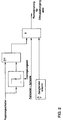
- Fig. 1
- ein Blockschaltbild einer erfindungsgemäßen Vorrichtung und
- Fig. 2
- ein Blockschaltbild eines Teilbereichs der Vorrichtung gemäß Fig. 1.
Diese Modelldrehzahl wurde bisher nach einem vollständig beendeten Schaltvorgang mit der Motordrehzahl initialisiert, was häufig zu einem Schaltruckeln führte.
Claims (6)
- Verfahren zur Dämpfung von Schaltruckeln bei einem Kraftfahrzeug, das einen Verbrennungsmotor, ein Schaltgetriebe, eine antriebsmäßig zwischen dem Verbrennungsmotor und dem Schaltgetriebe angeordnete ein- und ausrückbare Reibungskupplung und ein über ein Gaspedal betätigbares Motorleistungsstellglied aufweist, wobei die Motordrehzahl gemäß einer einem ruckelfreien Zustand entsprechenden Modelldrehzahl geregelt wird, dadurch gekennzeichnet, daß bei einem Schaltvorgang Sollwerte, insbesondere die Zielgangstufe und eine Motorzieldrehzahl während des Einkuppelns, bestimmt werden, und daß ein Ausgabesignal, insbesondere die Modelldrehzahl durch die ermittelte Motorzieldrehzahl initialisiert wird.
- Verfahren nach Anspruch 1, dadurch gekennzeichnet, daß die Zielgangstufe anhand des Verhältnisses zwischen Motordrehzahl und Fahrgeschwindigkeit erkannt wird und die Motorzieldrehzahl aus dem Produkt aus Fahrgeschwindigkeit und dem Motordrehzahl-Fahrgeschwindigkeit-Verhältnis der erkannten Zielgangstufe bestimmt wird.
- Verfahren nach Anspruch 1, dadurch gekennzeichnet, daß die Ruckeldämpfung für einen Schaltvorgang bei Vorliegen folgender Bedingungen durchgeführt wird:a) Betätigung der Kupplung oder eines mit dem Kupplungspedal gekoppelten Kupplungsschalters,b) Betätigung des Gaspedals undc) Erkennung der Zielgangstufe.
- Vorrichtung zur Dämpfung von Schaltruckeln bei einem Kraftfahrzeug, das einen Verbrennungsmotor, ein Schaltgetriebe, eine antriebsmäßig zwischen dem Verbrennungsmotor und dem Schaltgetriebe angeordnete ein- und ausrückbare Reibungskupplung und ein über ein Gaspedal betätigbares Motorleistungsstellglied aufweist, wobei die Vorrichtung die Motordrehzahl gemäß einer einem ruckelfreien Zustand entsprechenden Modelldrehzahl regelt, des Verhältnisses zwischen Motordrehzahl und Fahrgeschwindigkeit die Zielgangstufe erkennen und aus dem Produkt aus Fahrgeschwindigkeit und dem Motordrehzahl-Fahrgeschwindigkeit-Verhältnis der erkannten Zielgangstufe eine Motorzieldrehzahl bestimmen und mit dieser Motorzieldrehzahl die Modelldrehzahl initialisieren.
- Vorrichtung nach Anspruch 4, ferner gekennzeichnet durch einen Kupplungsschalter, der bereits durch Antippen des Kupplungspedals und bei noch in vollständiger Haftung befindlicher Reibungskupplung betätigt wird, einen die Betätigung des Gaspedals erfassenden Sensor, und eine die Zielgangstufe anhand des Verhältnisses zwischen Motordrehzahl und Fahrgeschwindigkeit erkennende Einrichtung, die einen Motordrehzahlsignaleingang und einen Fahrgeschwindigkeitssignaleingang aufweist, wobei die Ausgänge des Kupplungsschalters, des die Betätigung des Gaspedals erfassenden Sensors und der die Zielgangstufe erkennenden Einrichtung mit einem logischen Verknüpfungsglied verbunden sind.
- Vorrichtung nach Anspruch 4 oder 5, dadurch gekennzeichnet, daß der Kupplungsschalter mit einem Verzögerungsglied gekoppelt ist, wobei ein Ausgang des Kupplungsschalters und ein Ausgang des Verzögerungsgliedes mit einem logischen Verknüpfungsglied verbunden sind, welches ein Ausgangssignal abgibt, sobald zumindest an einem der beiden genannten Ausgänge ein Signal anliegt.
Applications Claiming Priority (2)
| Application Number | Priority Date | Filing Date | Title |
|---|---|---|---|
| DE19948157 | 1999-10-07 | ||
| DE19948157A DE19948157A1 (de) | 1999-10-07 | 1999-10-07 | Verfahren und Vorrichtung zur Dämpfung von Schaltruckeln bei einem Kraftfahrzeug |
Publications (3)
| Publication Number | Publication Date |
|---|---|
| EP1090801A2 true EP1090801A2 (de) | 2001-04-11 |
| EP1090801A3 EP1090801A3 (de) | 2002-08-14 |
| EP1090801B1 EP1090801B1 (de) | 2004-08-25 |
Family
ID=7924705
Family Applications (1)
| Application Number | Title | Priority Date | Filing Date |
|---|---|---|---|
| EP00119482A Expired - Lifetime EP1090801B1 (de) | 1999-10-07 | 2000-09-18 | Verfahren und Vorrichtung zur Dämpfung von Schaltruckeln bei einem Kraftfahrzeug |
Country Status (3)
| Country | Link |
|---|---|
| EP (1) | EP1090801B1 (de) |
| AT (1) | ATE274427T1 (de) |
| DE (2) | DE19948157A1 (de) |
Citations (1)
| Publication number | Priority date | Publication date | Assignee | Title |
|---|---|---|---|---|
| EP0512728B1 (de) | 1991-05-09 | 1996-01-17 | Eaton Corporation | Steuerungssystem/Verfahren zum weichen Hochschalten |
Family Cites Families (4)
| Publication number | Priority date | Publication date | Assignee | Title |
|---|---|---|---|---|
| DE3334711A1 (de) * | 1983-09-26 | 1985-04-04 | Wabco Westinghouse Fahrzeug | Gassteuereinrichtung fuer einen antriebsmotor |
| JPH04129842A (ja) * | 1990-09-19 | 1992-04-30 | Nissan Motor Co Ltd | エンジンと自動変速機の総合制御装置 |
| DE19703863A1 (de) * | 1997-02-03 | 1998-08-06 | Bosch Gmbh Robert | Verfahren und Vorrichtung zur Steuerung des Antriebsstrangs eines Kraftfahrzeugs |
| DE19916655B4 (de) * | 1999-04-14 | 2009-07-09 | Robert Bosch Gmbh | Verfahren und Vorrichtung zur Steuerung der Antriebseinheit eines Fahrzeugs |
-
1999
- 1999-10-07 DE DE19948157A patent/DE19948157A1/de not_active Withdrawn
-
2000
- 2000-09-18 EP EP00119482A patent/EP1090801B1/de not_active Expired - Lifetime
- 2000-09-18 DE DE50007549T patent/DE50007549D1/de not_active Expired - Lifetime
- 2000-09-18 AT AT00119482T patent/ATE274427T1/de not_active IP Right Cessation
Patent Citations (1)
| Publication number | Priority date | Publication date | Assignee | Title |
|---|---|---|---|---|
| EP0512728B1 (de) | 1991-05-09 | 1996-01-17 | Eaton Corporation | Steuerungssystem/Verfahren zum weichen Hochschalten |
Also Published As
| Publication number | Publication date |
|---|---|
| EP1090801A3 (de) | 2002-08-14 |
| ATE274427T1 (de) | 2004-09-15 |
| DE50007549D1 (de) | 2004-09-30 |
| DE19948157A1 (de) | 2001-05-10 |
| EP1090801B1 (de) | 2004-08-25 |
Similar Documents
| Publication | Publication Date | Title |
|---|---|---|
| DE19653855C1 (de) | Vorrichtung zur Steuerung eines Anfahrvorganges | |
| DE3636953C2 (de) | ||
| DE69402134T2 (de) | Steuerungsvorrichtung/-verfahren zur Unterstützung des Schaltvorganges mittels Motorbremse | |
| DE19815259B4 (de) | Vorrichtung zur Steuerung einer automatisierten Kupplung im Antriebsstrang | |
| DE3151351C2 (de) | Kraftfahrzeug-Antriebseinheit mit einer Steuervorrichtung | |
| WO2000074967A2 (de) | Verfahren zum betreiben einer getriebevorrichtung | |
| DE19716828A1 (de) | Vorrichtung zur Ansteuerung eines Drehmomentübertragungssystems | |
| DE2700821A1 (de) | Verfahren und vorrichtung zur einstellung des schaltrucks in kraftfahrzeugen | |
| DE19721034A1 (de) | Kraftfahrzeug | |
| DE19815260A1 (de) | Kraftfahrzeug | |
| DE19719614A1 (de) | Kraftfahrzeug | |
| EP1564446A2 (de) | Verfahren und Vorrichtung zum Steuern eines Gangwechsels in einem Parallelschaltgetriebe eines Fahrzeuges | |
| DE19824772A1 (de) | Vorrichtung zur Steuerung eines Einrückzustandes | |
| EP0628442B1 (de) | Anordnung zur Betätigung einer Reibungskupplung eines Kraftfahrzeugs | |
| DE10345906A1 (de) | Verfahren, Vorrichtung und deren Verwendung zum Betrieb eines Kraftfahrzeuges | |
| EP0928376A1 (de) | Automatisch gesteuerte kupplung | |
| DE3844286C2 (de) | Sicherheits-Notlaufverfahren und Sicherheits-Notlaufvorrichtung für Diesel-Brennkraftmaschinen | |
| DE19833838A1 (de) | Verfahren und Vorrichtung zur Steuerung der Geschwindigkeit eines Fahrzeugs | |
| DE19628787A1 (de) | Automatisch steuerbare Kupplung | |
| EP1375238B1 (de) | Antriebsmoment- und Kupplungsteuerung eines rollenden Fahrzeugs | |
| DE19815258B4 (de) | Kraftfahrzeug mit einem Getriebe und einer Vorrichtung zur Steuerung einer automatisierten Kupplung | |
| EP1090801B1 (de) | Verfahren und Vorrichtung zur Dämpfung von Schaltruckeln bei einem Kraftfahrzeug | |
| DE102009023783A1 (de) | Verfahren zur Einstellung einer Fahrgeschwindigkeit eines Kraftfahrzeuges | |
| EP1662185B1 (de) | Verfahren und Steuerungsvorrichtung zum sicheren Trennen eines Antriebsstranges | |
| DE19519703B4 (de) | Antriebseinrichtung für ein Kraftfahrzeug und Verfahren zum Betreiben derselben |
Legal Events
| Date | Code | Title | Description |
|---|---|---|---|
| PUAI | Public reference made under article 153(3) epc to a published international application that has entered the european phase |
Free format text: ORIGINAL CODE: 0009012 |
|
| AK | Designated contracting states |
Kind code of ref document: A2 Designated state(s): AT BE CH CY DE DK ES FI FR GB GR IE IT LI LU MC NL PT SE |
|
| AX | Request for extension of the european patent |
Free format text: AL;LT;LV;MK;RO;SI |
|
| PUAL | Search report despatched |
Free format text: ORIGINAL CODE: 0009013 |
|
| AK | Designated contracting states |
Kind code of ref document: A3 Designated state(s): AT BE CH CY DE DK ES FI FR GB GR IE IT LI LU MC NL PT SE |
|
| AX | Request for extension of the european patent |
Free format text: AL;LT;LV;MK;RO;SI |
|
| 17P | Request for examination filed |
Effective date: 20030214 |
|
| AKX | Designation fees paid |
Designated state(s): AT BE CH CY DE DK ES FI FR GB GR IE IT LI LU MC NL PT SE |
|
| 17Q | First examination report despatched |
Effective date: 20030904 |
|
| RIN1 | Information on inventor provided before grant (corrected) |
Inventor name: SCHULTALBERS, MATHIAS DIPL.-ING. Inventor name: MANNIGEL, DIETER |
|
| GRAP | Despatch of communication of intention to grant a patent |
Free format text: ORIGINAL CODE: EPIDOSNIGR1 |
|
| GRAS | Grant fee paid |
Free format text: ORIGINAL CODE: EPIDOSNIGR3 |
|
| GRAA | (expected) grant |
Free format text: ORIGINAL CODE: 0009210 |
|
| AK | Designated contracting states |
Kind code of ref document: B1 Designated state(s): AT BE CH CY DE DK ES FI FR GB GR IE IT LI LU MC NL PT SE |
|
| PG25 | Lapsed in a contracting state [announced via postgrant information from national office to epo] |
Ref country code: IT Free format text: LAPSE BECAUSE OF FAILURE TO SUBMIT A TRANSLATION OF THE DESCRIPTION OR TO PAY THE FEE WITHIN THE PRESCRIBED TIME-LIMIT;WARNING: LAPSES OF ITALIAN PATENTS WITH EFFECTIVE DATE BEFORE 2007 MAY HAVE OCCURRED AT ANY TIME BEFORE 2007. THE CORRECT EFFECTIVE DATE MAY BE DIFFERENT FROM THE ONE RECORDED. Effective date: 20040825 Ref country code: IE Free format text: LAPSE BECAUSE OF FAILURE TO SUBMIT A TRANSLATION OF THE DESCRIPTION OR TO PAY THE FEE WITHIN THE PRESCRIBED TIME-LIMIT Effective date: 20040825 Ref country code: FI Free format text: LAPSE BECAUSE OF FAILURE TO SUBMIT A TRANSLATION OF THE DESCRIPTION OR TO PAY THE FEE WITHIN THE PRESCRIBED TIME-LIMIT Effective date: 20040825 Ref country code: GB Free format text: LAPSE BECAUSE OF FAILURE TO SUBMIT A TRANSLATION OF THE DESCRIPTION OR TO PAY THE FEE WITHIN THE PRESCRIBED TIME-LIMIT Effective date: 20040825 Ref country code: NL Free format text: LAPSE BECAUSE OF FAILURE TO SUBMIT A TRANSLATION OF THE DESCRIPTION OR TO PAY THE FEE WITHIN THE PRESCRIBED TIME-LIMIT Effective date: 20040825 Ref country code: CY Free format text: LAPSE BECAUSE OF FAILURE TO SUBMIT A TRANSLATION OF THE DESCRIPTION OR TO PAY THE FEE WITHIN THE PRESCRIBED TIME-LIMIT Effective date: 20040825 |
|
| REG | Reference to a national code |
Ref country code: GB Ref legal event code: FG4D Free format text: NOT ENGLISH |
|
| REG | Reference to a national code |
Ref country code: CH Ref legal event code: EP |
|
| PG25 | Lapsed in a contracting state [announced via postgrant information from national office to epo] |
Ref country code: AT Free format text: LAPSE BECAUSE OF NON-PAYMENT OF DUE FEES Effective date: 20040918 Ref country code: LU Free format text: LAPSE BECAUSE OF NON-PAYMENT OF DUE FEES Effective date: 20040918 |
|
| REG | Reference to a national code |
Ref country code: IE Ref legal event code: FG4D Free format text: GERMAN |
|
| PG25 | Lapsed in a contracting state [announced via postgrant information from national office to epo] |
Ref country code: CH Free format text: LAPSE BECAUSE OF NON-PAYMENT OF DUE FEES Effective date: 20040930 Ref country code: BE Free format text: LAPSE BECAUSE OF NON-PAYMENT OF DUE FEES Effective date: 20040930 Ref country code: LI Free format text: LAPSE BECAUSE OF NON-PAYMENT OF DUE FEES Effective date: 20040930 Ref country code: MC Free format text: LAPSE BECAUSE OF NON-PAYMENT OF DUE FEES Effective date: 20040930 |
|
| REF | Corresponds to: |
Ref document number: 50007549 Country of ref document: DE Date of ref document: 20040930 Kind code of ref document: P |
|
| PG25 | Lapsed in a contracting state [announced via postgrant information from national office to epo] |
Ref country code: DK Free format text: LAPSE BECAUSE OF FAILURE TO SUBMIT A TRANSLATION OF THE DESCRIPTION OR TO PAY THE FEE WITHIN THE PRESCRIBED TIME-LIMIT Effective date: 20041125 Ref country code: GR Free format text: LAPSE BECAUSE OF FAILURE TO SUBMIT A TRANSLATION OF THE DESCRIPTION OR TO PAY THE FEE WITHIN THE PRESCRIBED TIME-LIMIT Effective date: 20041125 Ref country code: SE Free format text: LAPSE BECAUSE OF FAILURE TO SUBMIT A TRANSLATION OF THE DESCRIPTION OR TO PAY THE FEE WITHIN THE PRESCRIBED TIME-LIMIT Effective date: 20041125 |
|
| PG25 | Lapsed in a contracting state [announced via postgrant information from national office to epo] |
Ref country code: ES Free format text: LAPSE BECAUSE OF FAILURE TO SUBMIT A TRANSLATION OF THE DESCRIPTION OR TO PAY THE FEE WITHIN THE PRESCRIBED TIME-LIMIT Effective date: 20041206 |
|
| NLV1 | Nl: lapsed or annulled due to failure to fulfill the requirements of art. 29p and 29m of the patents act | ||
| GBV | Gb: ep patent (uk) treated as always having been void in accordance with gb section 77(7)/1977 [no translation filed] |
Effective date: 20040825 |
|
| REG | Reference to a national code |
Ref country code: IE Ref legal event code: FD4D |
|
| BERE | Be: lapsed |
Owner name: VOLKSWAGEN A.G. Effective date: 20040930 |
|
| ET | Fr: translation filed | ||
| REG | Reference to a national code |
Ref country code: CH Ref legal event code: PL |
|
| PLBE | No opposition filed within time limit |
Free format text: ORIGINAL CODE: 0009261 |
|
| STAA | Information on the status of an ep patent application or granted ep patent |
Free format text: STATUS: NO OPPOSITION FILED WITHIN TIME LIMIT |
|
| 26N | No opposition filed |
Effective date: 20050526 |
|
| BERE | Be: lapsed |
Owner name: *VOLKSWAGEN A.G. Effective date: 20040930 |
|
| PG25 | Lapsed in a contracting state [announced via postgrant information from national office to epo] |
Ref country code: PT Free format text: LAPSE BECAUSE OF NON-PAYMENT OF DUE FEES Effective date: 20050125 |
|
| PGFP | Annual fee paid to national office [announced via postgrant information from national office to epo] |
Ref country code: DE Payment date: 20120930 Year of fee payment: 13 |
|
| PGFP | Annual fee paid to national office [announced via postgrant information from national office to epo] |
Ref country code: FR Payment date: 20121017 Year of fee payment: 13 |
|
| REG | Reference to a national code |
Ref country code: DE Ref legal event code: R082 Ref document number: 50007549 Country of ref document: DE |
|
| REG | Reference to a national code |
Ref country code: DE Ref legal event code: R119 Ref document number: 50007549 Country of ref document: DE |
|
| REG | Reference to a national code |
Ref country code: DE Ref legal event code: R079 Ref document number: 50007549 Country of ref document: DE Free format text: PREVIOUS MAIN CLASS: B60K0041020000 Ipc: F16H0063500000 |
|
| REG | Reference to a national code |
Ref country code: FR Ref legal event code: ST Effective date: 20140530 |
|
| REG | Reference to a national code |
Ref country code: DE Ref legal event code: R119 Ref document number: 50007549 Country of ref document: DE Effective date: 20140401 Ref country code: DE Ref legal event code: R079 Ref document number: 50007549 Country of ref document: DE Free format text: PREVIOUS MAIN CLASS: B60K0041020000 Ipc: F16H0063500000 Effective date: 20140527 |
|
| PG25 | Lapsed in a contracting state [announced via postgrant information from national office to epo] |
Ref country code: FR Free format text: LAPSE BECAUSE OF NON-PAYMENT OF DUE FEES Effective date: 20130930 Ref country code: DE Free format text: LAPSE BECAUSE OF NON-PAYMENT OF DUE FEES Effective date: 20140401 |