EP1090596A1 - Intramedullary nail for the humerus - Google Patents
Intramedullary nail for the humerus Download PDFInfo
- Publication number
- EP1090596A1 EP1090596A1 EP00810689A EP00810689A EP1090596A1 EP 1090596 A1 EP1090596 A1 EP 1090596A1 EP 00810689 A EP00810689 A EP 00810689A EP 00810689 A EP00810689 A EP 00810689A EP 1090596 A1 EP1090596 A1 EP 1090596A1
- Authority
- EP
- European Patent Office
- Prior art keywords
- intramedullary nail
- wires
- claw
- nail according
- intramedullary
- Prior art date
- Legal status (The legal status is an assumption and is not a legal conclusion. Google has not performed a legal analysis and makes no representation as to the accuracy of the status listed.)
- Granted
Links
Images


Classifications
-
- A—HUMAN NECESSITIES
- A61—MEDICAL OR VETERINARY SCIENCE; HYGIENE
- A61B—DIAGNOSIS; SURGERY; IDENTIFICATION
- A61B17/00—Surgical instruments, devices or methods, e.g. tourniquets
- A61B17/56—Surgical instruments or methods for treatment of bones or joints; Devices specially adapted therefor
- A61B17/58—Surgical instruments or methods for treatment of bones or joints; Devices specially adapted therefor for osteosynthesis, e.g. bone plates, screws, setting implements or the like
- A61B17/68—Internal fixation devices, including fasteners and spinal fixators, even if a part thereof projects from the skin
- A61B17/72—Intramedullary pins, nails or other devices
- A61B17/7216—Intramedullary pins, nails or other devices for bone lengthening or compression
- A61B17/7225—Intramedullary pins, nails or other devices for bone lengthening or compression for bone compression
-
- A—HUMAN NECESSITIES
- A61—MEDICAL OR VETERINARY SCIENCE; HYGIENE
- A61B—DIAGNOSIS; SURGERY; IDENTIFICATION
- A61B17/00—Surgical instruments, devices or methods, e.g. tourniquets
- A61B17/56—Surgical instruments or methods for treatment of bones or joints; Devices specially adapted therefor
- A61B17/58—Surgical instruments or methods for treatment of bones or joints; Devices specially adapted therefor for osteosynthesis, e.g. bone plates, screws, setting implements or the like
- A61B17/68—Internal fixation devices, including fasteners and spinal fixators, even if a part thereof projects from the skin
- A61B17/72—Intramedullary pins, nails or other devices
- A61B17/7233—Intramedullary pins, nails or other devices with special means of locking the nail to the bone
- A61B17/7258—Intramedullary pins, nails or other devices with special means of locking the nail to the bone with laterally expanding parts, e.g. for gripping the bone
- A61B17/7266—Intramedullary pins, nails or other devices with special means of locking the nail to the bone with laterally expanding parts, e.g. for gripping the bone with fingers moving radially outwardly
-
- A—HUMAN NECESSITIES
- A61—MEDICAL OR VETERINARY SCIENCE; HYGIENE
- A61B—DIAGNOSIS; SURGERY; IDENTIFICATION
- A61B17/00—Surgical instruments, devices or methods, e.g. tourniquets
- A61B17/16—Bone cutting, breaking or removal means other than saws, e.g. Osteoclasts; Drills or chisels for bones; Trepans
- A61B17/17—Guides or aligning means for drills, mills, pins or wires
- A61B17/1725—Guides or aligning means for drills, mills, pins or wires for applying transverse screws or pins through intramedullary nails or pins
-
- A—HUMAN NECESSITIES
- A61—MEDICAL OR VETERINARY SCIENCE; HYGIENE
- A61B—DIAGNOSIS; SURGERY; IDENTIFICATION
- A61B17/00—Surgical instruments, devices or methods, e.g. tourniquets
- A61B17/16—Bone cutting, breaking or removal means other than saws, e.g. Osteoclasts; Drills or chisels for bones; Trepans
- A61B17/17—Guides or aligning means for drills, mills, pins or wires
- A61B17/1739—Guides or aligning means for drills, mills, pins or wires specially adapted for particular parts of the body
- A61B17/1778—Guides or aligning means for drills, mills, pins or wires specially adapted for particular parts of the body for the shoulder
Landscapes
- Health & Medical Sciences (AREA)
- Orthopedic Medicine & Surgery (AREA)
- Surgery (AREA)
- Life Sciences & Earth Sciences (AREA)
- Heart & Thoracic Surgery (AREA)
- Nuclear Medicine, Radiotherapy & Molecular Imaging (AREA)
- Engineering & Computer Science (AREA)
- Biomedical Technology (AREA)
- Neurology (AREA)
- Medical Informatics (AREA)
- Molecular Biology (AREA)
- Animal Behavior & Ethology (AREA)
- General Health & Medical Sciences (AREA)
- Public Health (AREA)
- Veterinary Medicine (AREA)
- Surgical Instruments (AREA)
Abstract
Description
Die Erfindung handelt von einem Marknagel vorzugsweise für den Humerus mit einem Befestigungskopf für eine Einschlag- und Zielvorrichtung, wobei der Marknagel mindestens eine Querbohrung anschliessend an den Befestigungskopf aufweist, und mit einer Eintrittsspitze, in deren Nähe radial Verankerungselemente ausfahrbar sind.The invention relates to an intramedullary nail, preferably for the humerus with a mounting head for a striking and aiming device, the Intramedullary nail at least one cross hole next to the Has mounting head, and with an inlet tip, in the vicinity of which radially Anchoring elements are extendable.
Die Marknagelung an sich ist eine schonende Methode zur operativen Behandlung von Frakturen langer Röhrenknochen. Wichtige Vorteile bestehen in einem sehr kleinen Zugang ohne nennenswerte Narbenbildung und in einer geschlossenen Reposition der Fraktur. Um eine stabile und rotationssichere intramedulläre Frakturschienung zu erhalten, werden Marknägel an beiden Enden mittels Stiften oder Schrauben im Knochen verriegelt.The intramedullary nailing itself is a gentle method for operative Treatment of long bones fractures. There are important advantages in a very small access with no significant scarring and in one closed reduction of the fracture. To be stable and rotation-proof To obtain intramedullary fracture splinting, intramedullary nails are attached to both The ends are locked in the bone by means of pins or screws.
Bei der Behandlung von Oberarmbrüchen wird diese Verriegelung an der Einführungsstelle (insertionsnah) mit Hilfe eines Zielbügels durchgeführt, der am Ende des Nagels befestigt ist und gleichzeitig als Handgriff zur besseren Einführbarkeit des Marknagels dient. In ihm sind Führungen für den Bohrer vorgesehen, der somit die im Implantat vorhandenen Löcher von aussen exakt treffen kann. Ein Problem bei fast allen Humerus-Marknägeln besteht wegen ihrer geringen Durchmesser bei einer Verriegelung am insertionsfernen Ende. Da ein Auffinden von entfernten Implantatlöchern mit einem langen Zielgerät sehr umständlich ist und sich der Nagel über die Strecke des gesamten Humerus verbiegt und verwindet, erfolgt die insertionsferne Verriegelung Freihand unter Röntgenbildverstärker-Durchleuchtung. Dabei muss ein vorhandenes, ca. 4 mm grosses Loch im Durchleuchtung. Dabei muss ein vorhandenes, ca. 4 mm grosses Loch im Implantat von aussen gesucht, und mit dem Bohrer getroffen werden, was mit Strahlenbelastung und einem hohen Zeitaufwand einhergeht.When treating upper arm fractures, this lock is on the Introductory point (close to insertion) carried out with the help of a aiming arm, the is attached to the end of the nail and at the same time as a handle for better Introducibility of the intramedullary nail serves. In it are guides for the drill provided that the holes present in the implant from the outside can hit exactly. There is a problem with almost all humeral intramedullary nails because of their small diameter when locked on end far from insertion. Since finding removed implant holes with a long target device is very cumbersome and the nail on the The route of the entire humerus is bent and twisted Freely insert-free locking under X-ray image intensifier fluoroscopy. An existing, approx. 4 mm hole in the Fluoroscopy. An existing, approx. 4 mm hole in the Looking for implant from the outside, and hit with the drill, what with Radiation exposure and a lot of time goes hand in hand.
Marknägel mit radial ausfahrbaren Verankerungselementen in der Nähe der Eintrittsspitze sind in der Patentschrift U.S. 5,810,820 gezeigt. Radial austretende Drahtspitzen bohren sich in das Knochenmaterial und geben Halt in axialer Richtung. Die mit Spitzen versehenen Drähte haben eine zylindrische Form und sind im eingezogenen Zustand jeweils in Führungen gelagert. Das Prinzip des radialen Austritts beruht darauf, dass die Drähte durch achsiales Zustellen derart in eine radiale Umlenkung gepresst werden, dass sie sich plastisch verformen. Durch axiales Rückstellen werden die Drähte wieder plastisch in eine zylindrische Form zurückverformt. Diese Anordnung hat den Nachteil, dass der Draht zur Richtungsänderung jeweils plastisch verformt werden muss. Eine Funktionskontrolle vor dem Einsetzen des Marknagels birgt die Gefahr in sich, dass sich die Drähte durch die plastische Deformation aufhärten und spröder werden. Ein Weglassen der Funktionskontrolle ist auch nicht sehr sinnvoll. Im weiteren müssen die Drähte innerhalb des Marknagels sehr genau allseitig geführt werden, damit kein Knicken stattfindet.Intramedullary nails with radially extendable anchoring elements near the Entry peaks are in U.S. patent 5,810,820. Radial emerging wire tips drill into the bone material and give Stop in the axial direction. The tipped wires have one cylindrical shape and are in the retracted state in guides stored. The principle of the radial exit is based on the wires are pressed into a radial deflection by axial infeed, that they deform plastically. By axially resetting the The wires are plastically deformed back into a cylindrical shape. This Arrangement has the disadvantage that the wire for changing the direction in each case must be plastically deformed. A functional check before insertion of the intramedullary nail carries the risk that the wires can get through the harden plastic deformation and become brittle. Omitting the Functional control is also not very useful. Furthermore, the Wires inside the intramedullary nail are guided very precisely on all sides no buckling takes place.
Bei einem Marknagel für den Humerus kommt erschwerend hinzu, dass der Durchmesser des Markraums klein bemessen ist und nur Marknägel mit kleinen Durchmessern zulässt. Individuelle, den Draht voll umschliessende Führungen sind nur noch mit grossem Aufwand herstellbar. Es ist daher Aufgabe der Erfindung, einen einfach konzipierten Humerus-Marknagel aufzuzeigen.With an intramedullary nail for the humerus, the fact that the The diameter of the medullary canal is small and only with intramedullary nails allows small diameters. Individual, fully enclosing the wire Guided tours can only be produced with great effort. It is therefore Object of the invention, a simply designed humeral intramedullary nail to show.
Diese Aufgabe wird mit den Kennzeichen des unabhängigen Anspruchs 1
dadurch gelöst, dass die Verankerungselemente in einer Kralle aus
gekrümmten Drähten zusammengefasst sind, wobei die Drähte in einem nicht
ausgefahrenen Zustand innerhalb des Marknagels elastisch deformiert sind
und mit einer axialen Zustellung der Kralle radial herausspringen und ihre
ursprüngliche gekrümmte Form annehmen. This object is achieved with the characteristics of
Diese Anordnung hat den Vorteil, dass die Arbeit für das radiale Eindringen
in Knochenmaterial mit dem Zurückziehen der Kralle in den Schaft des
Marknagels bereits gespeichert ist. Eine Funktionskontrolle ist jederzeit
möglich, da die Drähte nur im elastischen Bereich deformiert werden. Die
unabhängigen Ansprüche 2 bis 12 sind vorteilhafte Weiterbildungen der
Erfindung. Für den einzelnen Draht genügt eine offene, zylindrische
Führungsrinne, welche die Drahtspitze führt und durch einen radialen
Durchbruch unterbrochen ist. Die Führungsrinnen lassen sich auch bei
kleinen Schaftabmessungen durch Stossen herstellen, wenn die Spitze des
Marknagels später aufsetzbar ist. Die radialen Durchbrüche verjüngen sich
zur Eintrittsspitze des Marknagels hin und zentrieren die Drähte. Gleichzeitig
findet eine seitliche Abstützung an den radial austretenden Drähten statt.
Durch die Führungsrinnen entsteht an den Drahtspitzen bereits eine
Verdrehsicherung. Zusätzlich können Nocken am Fuss der Kralle angebracht
sein, die als zusätzliche Verdrehsicherung in den Führungsrinnen laufen. Im
Fuss der Kralle ist eine Stellschraube drehbar gelagert, welche jedoch in
axialer Richtung an der Kralle fixiert ist. Durch das Zusammenfassen der
Drähte in einer Kralle, kann die Lage der vorgebogenen Drähte zueinander
vorgegeben werden. Anstatt die Ebenen, in denen die Drähte abgebogen
sind, konzentrisch durch die Längsachse laufen zu lassen, wird mehr Raum
für die elastische Deformation der Drähte gewonnen, wenn diese Ebenen
einen Abstand zur Längsachse aufweisen. Querbohrungen, die in der Nähe
des Befestigungskopfes liegen, können trotz der kleinen Durchmesser für
einen Humerus-Marknagel mit einem Zielbügel angebracht werden, da
dessen Armlänge sehr kurz bemessen ist. Wenn die Stellschraube von der
Seite der Spitze des Marknagels einbringbar ist, kann der hohle Marknagel
im Bereich zwischen Stellschraube und Befestigungskopf eine Krümmung
aufweisen. In einem solchen Fall ist ein biegbares Schraubwerkzeug
notwendig, um die Stellschraube zu verstellen. Der vorliegende Marknagel ist
nicht auf den Humerus beschränkt und kann grundsätzlich auch bei anderen
Röhrenknochen eingesetzt werden.This arrangement has the advantage of working for radial penetration
in bone material with the retraction of the claw in the shaft of the
Marknagels is already saved. A function check is possible at any time
possible because the wires are only deformed in the elastic area. The
Eine weitere Verbesserung, die ganz allgemein für Marknägel ihre Anwendung findet, besteht darin, einen Marknagel in mindestens einer vorgegebenen Zone seines Schaftes biegeelastisch zu gestalten, damit er einer Krümmung des Markkanals folgen kann. Dabei versteht es sich, dass diese biegeelastische Zone nicht in der Nähe einer Bruchstelle eines Röhrenknochens liegen sollte. Besondere Vorteile ergeben sich, wenn diese biegeelastische Zone auch noch als Zugfeder verwendbar ist, weil sie beispielsweise als ein- oder mehrgängige Wendel ausgeführt ist, deren Windungen im spannungslosen Zustand einen geringen vorgegebenen Abstand aufweisen, derart, dass bei einem vollständigen Zusammenpressen dieser Schraubenfeder deren Windungen nur elastisch deformiert sind, um das Einschlagen des Marknagels zu erleichtern. Nach dem Verankern eines ersten Endes des Marknagels kann vom entgegengesetzten Ende des Marknagels Zug aufgebracht werden, welcher diese Schraubenfeder in Zugrichtung spannt, und anschliessend unter Beibehaltung der Zugkraft an diesem entgegengesetzten Ende des Marknagels eine weitere Verankerung angebracht werden. Die Schraubenfeder als Zugfeder übt dann über die beidseitigen Verankerungen des Marknagels eine Kompression auf den Knochen resp. auf eine dazwischenliegende Bruchstelle aus, wobei sich die Kompression wegen der im Vergleich zum starren Marknagel viel weicheren Federwirkung der Zugfeder nicht so schnell abbauen kann, da eine geringe Änderung des Federweges nur eine geringe Änderung der Kompressionskraft verursacht. Die Einführung einer solchen biegeelastischen Zone ist überall dort von besonderem Vorteil, wo die Verankerung der beiden Enden eines Marknagels unabhängig von der Lage dieser beiden Enden zueinander erfolgen kann. Bei einem hohlen Marknagel wie er in den nachfolgenden Ausführungsbeispielen aufgezeigt ist, wird die Verankerung der beiden Enden des hohlen Marknagels unabhängig voneinander von dem Ende des Befestigungskopfes aus vorgenommen. Die Biege- und Zugfeder ist daher als Wendel aus dem hohlen Schaft geschnitten, um einem biegsamen Schraubendreher auf der Innenseite Platz zu lassen. Eine Ausführung eines vollen Marknagels mit einer Biege und/oder Zugfeder in einer vorgegebenen Zone ist ebenfalls sinnvoll, wenn die Verankerung der beiden Enden unabhängig von ihrer Position zueinander erfolgt. In der Patentanmeldung WO 98/02104 ist ein voller, durch ein Bohrstück verlängerter Marknagel gezeigt, an dessen beiden Enden unabhängig voneinander eine Zielvorrichtung aufsetzbar ist, um das jeweilige Ende zu verankern. Auch hier hat eine im Mittelteil zwischen den Querbohrungen liegende biegeelastische und eventuell auch noch zugelastische Zone keinen Einfluss auf das Anfahren der Querbohrungen. Wenn eine solche biege- und eventuell zugelastische Zone geplant ist, sind Biegeauslenkungen von mehr als 2° sinnvoll. Bei starren gekrümmten Marknägeln sind Biegezonen mit einer Biegeauslenkung von 4° bis 9° üblich. In diesem Bereich sollten auch biegeelastische Marknägel auslenkbar sein. Wie eine solche biegeelastische Zone aussehen kann, wird in der EP-B-0 614 020 für ein flexibles Schraubwerkzeug beschrieben und ist auf einen Marknagel übertragbar, wenn der Aussendurchmesser der biegeelastischen Zone nicht grösser als der Aussendurchmesser des starren Teils ist. Grundsätzlich sind alle Formen von biegeelastischen Zugfedern möglich, solange sie nicht über den Schaftdurchmesser vorstehen.Another improvement that is quite common for intramedullary nails Application is to insert an intramedullary nail into at least one to design the predetermined zone of its shaft so that it is flexible can follow a curvature of the medullary canal. It goes without saying that this flexurally elastic zone is not in the vicinity of a breaking point Tubular bone should lie. There are special advantages if these flexible zone can also be used as a tension spring because it is designed, for example, as a single or multi-turn spiral, the Turns in the de-energized state a small predetermined Have a distance such that when fully pressed together this coil spring whose turns are only elastically deformed to to facilitate driving in the intramedullary nail. After anchoring one first end of the intramedullary nail can be from the opposite end of the Marknagels train are applied, which this coil spring in Tension direction tensions, and then while maintaining the tension further anchoring this opposite end of the intramedullary nail be attached. The coil spring as a tension spring then exercises over the compression of the intramedullary nail on both sides Bones resp. to an intermediate break, whereby the Compression because of the much softer compared to the rigid intramedullary nail Spring action of the tension spring can not degrade so quickly because of a low Change in travel only a small change in compression force caused. The introduction of such a flexible zone is everywhere of particular advantage where the anchoring of the two ends of a Intramedullary nail regardless of the location of these two ends to each other can be done. For a hollow intramedullary nail like the one below Embodiments is shown, the anchoring of the two Ends of the hollow intramedullary nail independently of the end of the Fastening head made from. The bending and tension spring is therefore as Helix cut from the hollow shaft to make it flexible Leave a screwdriver on the inside. An execution of a full intramedullary nail with a bend and / or tension spring in a given Zone is also useful when anchoring the two ends regardless of their position to each other. In the patent application WO 98/02104 is a full intramedullary nail elongated by a drill bit shown, at the two ends independently of one another Target device can be placed to anchor the respective end. Here too has a flexible elastic in the middle section between the cross holes and possibly also elastic zone has no influence on the Approaching the cross holes. If such a bending and possibly elastic zone is planned, bending deflections of more than 2 ° sensible. With rigid curved intramedullary nails, there are bending zones with a Bending deflection from 4 ° to 9 ° is common. In this area too bendable intramedullary nails can be deflected. How such a flexible Zone can be seen in EP-B-0 614 020 for a flexible Described screwing tool and can be transferred to an intramedullary nail, if the outer diameter of the flexible zone is not greater than is the outside diameter of the rigid part. Basically, all forms of flexible tension springs, as long as they do not over the Protrude shaft diameter.
Im folgenden wird die Erfindung anhand von Ausführungsbeispielen beschrieben. Es zeigen:
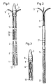
- Fig. 1:
- Schematisch eine vergrösserte Seitenansicht eines erfindungsgemässen Marknagels;
- Fig. 2
- schematisch den Innenteil des Marknagels von Fig. 1;
- Fig. 3
- schematisch den Marknagel von Fig. 1 mit eingezogener Kralle;
- Fig. 4
- schematisch eine starke Vergrösserung eines erfindungsgemässen Marknagels im Bereich der Führungsrinnen;
- Fig. 5
- schematisch einen Schnitt im oberen Bereich der radialen Durchbrüche von Fig. 4;
- Fig. 6
- schematisch einen Schnitt im unteren Bereich der radialen Durchbrüche von Fig. 4;
- Fig. 7
- schematisch eine Anordnung wie in Fig. 6, bei der die Drähte mit ihren Krümmungsebenen einen Abstand zur Längsachse aufweisen;
- Fig. 8
- schematisch einen Marknagel mit Zielbügel und mit einer Krümmung oberhalb der Querbohrungen; und
- Fig. 9
- schematisch einen Marknagel analog zu Fig. 8, bei dem die Krümmung durch eine biege- und zugelastische Zone ersetzt ist.
- Fig. 1:
- Schematically, an enlarged side view of an intramedullary nail according to the invention;
- Fig. 2
- schematically the inner part of the intramedullary nail of Fig. 1;
- Fig. 3
- schematically the intramedullary nail of Figure 1 with the claw retracted.
- Fig. 4
- schematically a large enlargement of an intramedullary nail according to the invention in the area of the guide channels;
- Fig. 5
- schematically shows a section in the upper region of the radial openings of Fig. 4;
- Fig. 6
- schematically shows a section in the lower region of the radial openings of Fig. 4;
- Fig. 7
- schematically an arrangement as in Figure 6, in which the wires are at a distance from the longitudinal axis with their planes of curvature.
- Fig. 8
- schematically an intramedullary nail with aiming arm and with a curvature above the cross holes; and
- Fig. 9
- schematically a medullary nail analogous to FIG. 8, in which the curvature is replaced by a bending and elastic zone.
In den Figuren ist ein Marknagel vorzugsweise für den Humerus gezeigt mit einem Befestigungskopf für eine Einschlag- und Zielvorrichtung, wobei der Marknagel mindestens eine Querbohrung anschliessend an den Befestigungskopf aufweist, und mit einer Eintrittsspitze, in deren Nähe radial Verankerungselemente ausfahrbar sind. Die Verankerungselemente sind in einer Kralle aus gekrümmten Drähten zusammengefasst, wobei die Drähte in einem nicht ausgefahrenen Zustand innerhalb des Marknagels elastisch deformiert sind und mit einer axialen Zustellung der Kralle radial herausspringen und ihre ursprüngliche gekrümmte Form annehmen.In the figures, an intramedullary nail is shown preferably for the humerus a mounting head for a striking and aiming device, the Intramedullary nail at least one cross hole next to the Has mounting head, and with an inlet tip, in the vicinity of which radially Anchoring elements are extendable. The anchoring elements are in a claw of curved wires combined, the wires in elastic in an undeveloped state within the intramedullary nail are deformed and with an axial infeed of the claw radially jump out and assume their original curved shape.
In den nachfolgenden Figuren sind die Hinweiszeichen gleich verwendet.In the following figures, the information signs are used in the same way.
In Figur 1 und 2 besitzt ein hohler Marknagel einen Befestigungskopf 1, an
welchen Querbohrungen 2 anschliessen und einen Schaft 19 mit einer
nachträglich montierten Spitze 3. Unterhalb der Spitze 3 sind radiale
Durchbrüche 8 angebracht, aus denen gekrümmte Drähte 6 austreten, die in
einer Kralle 5 zusammengefasst sind. Die Drähte 6 der Kralle 5 sind in einem
Fuss 13 fest verankert und sind in einer Krümmung radial abgebogen. Im
Fuss 13 ist eine Stellschraube 14 drehbar gelagert, jedoch in axialer
Richtung fixiert. Zur Stellschraube 14 besteht ein Gegengewinde 20 im
Schaft 19. Der Innenteil (Figur 2) wird bei abgenommener Spitze 3 von oben
eingeschoben bis die Stellschraube 14 am Gewinde 20 ansteht und mit
einem Schraubwerkzeug von der Gegenseite an ihrem Innensechskant 23
weiter hineinbewegt wird. Die Kralle 5 wird soweit in den Schaft 19
hineingezogen, bis die Drähte 6 vollständig verschwunden sind und mit ihren
Spitzen 9 die radialen Durchbrüche 8 überfahren haben. Die Drähte 6 sind so
dimensioniert, dass sie durch ihre Streckung nur elastisch deformiert werden.
Auf der Innenseite des Schaftes 19 sind Führungsrinnen 7 in Längsrichtung
angebracht, die sich mit den Durchbrüchen 8 decken und die Drahtspitzen 9
führen und gegen Verdrehung sichern. Eine zusätzliche Drehsicherung ist
durch Nocken 21 am Fuss 13 der Kralle möglich, wenn die Nocken 21 in die
Führungsrinnen 7 eingreifen. Durch Heraus- und Hineinschrauben der
Stellschraube 14 kann die Kralle auf und ab bewegt werden. Sobald die
Krallenspitzen 9 von unten kommend die Durchbrüche 8 erreichen, springen
sie radial nach aussen und bohren sich in einen sie umgebenden
Röhrenknochen, falls der Marknagel in diesen eingeschlagen ist. Durch ein
Fortsetzen der Axialbewegung wird der gestreckte Teil vollständig zur
selbständigen Krümmung freigegeben.In FIGS. 1 and 2, a hollow intramedullary nail has a
Am Beispiel der Figuren 4, 5 und 6 wird der Aufbau genauer erklärt. Der
Schaft 19 des Marknagels hat einen Aussendurchmesser von 6 mm und
besteht aus einem Metallrohr, beispielsweise Stahl oder Titan, auf welches
eine Spitze 3 mit Gewinde 27 aufschraubbar ist. Auf der Innenseite dieses
Rohrs sind fünf Führungsrinnen 7 mit einer möglichst grossen Breite 10
gestossen, um die Spitzen 9 der Kralle 5 zu führen und elastisch deformiert
zu halten. Die Drähte 6 der Kralle 5 sind aus dem Fuss 13 zunächst
zylindrisch und parallel zur Längsachse 12 herausgeführt und im
spannungsfreien Zustand mit einem Krümmungsradius von 8 mm radial nach
aussen um etwa 90° gekrümmt. Bei der Montage der Kralle 5 werden die
Krallenspitzen 9 zwangsläufig in die Führungsrinnen 7 eingezogen und
elastisch vorgespannt. Wegen der Krümmung der Drähte 6 kann die Kralle 5
mit ihren Spitzen 9 die radialen Durchbrüche 8 auf dem Weg nach innen
überfahren. Wird jedoch die Kralle nach aussen verschoben, dann werden
die vorgespannten Spitzen 9 zwangsläufig von den Durchbrüchen 8, welche
eine grösste Breite 10 der Führungsrinnen 7 aufweisen, eingefangen und -
weil sich die Durchbrüche 8 zur Spitze 3 des Marknagels verjüngen - zentriert
und seitlich abgestützt. Dabei bewegen sich die Drähte 6 in dem Mass, wie
sie in axialer Richtung freigegeben werden, radial nach aussen. The structure is explained in more detail using the example of FIGS. 4, 5 and 6. The
In Figur 6 erkennt man, dass die Ebenen der Drahtkrümmung konzentrisch
auf die Längsachse 12 ausgerichtet sind und relativ wenig Raum für die
Streckung der Drähte zugestehen.In Figure 6 it can be seen that the planes of the wire curvature are concentric
are aligned on the
In Figur 7 ist daher eine Anordnung gezeigt, bei der die Ebenen der
Drahtkrümmung um einen Abstand 17 von der Längsachse 12 versetzt an der
Längsachse vorbeilaufen und einen wesentlich grösseren Raum bei der
Streckung der Drähte 6 zu Verfügung stellen. Der Draht darf in diesem Fall
dicker und steifer als in Figur 6 sein und wird immer noch in seinem
elastischen Bereich deformiert. Da sich der Draht nur mit seiner Spitze 9
selber führt, kann er mit seinem zylindrischen Teil, der im Fuss 13 abgestützt
wird, so lang ausgeführt werden, dass ein Teil der Krümmung beim
eingezogenen Draht durch Krümmung des zylindrischen Teils in
Gegenrichtung aufgenommen wird (siehe Figur 3). Der gestreckte Draht 6'
erhält dann eine S-förmige Krümmung.FIG. 7 therefore shows an arrangement in which the levels of the
Wire curvature offset by a
In Figur 8 erweitert sich der Schaft 19 des Marknagels zu einem
Befestigungskopf 1. Eine in einer vorgegebenen Position aufsteckbare
Einschlag- und Zielvorrichtung ist mit einer hohlen Befestigungsschraube 25
am Kopf 1 angeschraubt und ermöglicht es über einen parallel zum Schaft
geführten Zielbügel 26, Querbohrungen 2 im eingeschlagenen Schaft 19
aufzufinden und mit Verankerungsschrauben zu versehen, um zu der
Verankerung durch die Kralle 5 an der Spitze 3 des Marknagels eine zweite
Verankerung am Befestigungskopf 1 zu erreichen. Dabei darf der Marknagel
auch eine leichte Krümmung 22 zur Längsachse 12 des Befestigungskopfes
1 aufweisen, wenn der Schraubendreher für die Stellschraube 14 des
Innenteils (Figur 2) in Biegerichtung flexibel ist. Der implantierte Marknagel
erhält eine Verschlusskappe (hier nicht gezeigt), die den Innenraum von
einwachsendem Gewebe freihält. Ebenso sind die Querbohrungen 2 durch
Knochenschrauben weitgehend verschlossen. Zum Entfernen des
Marknagels müssen Verschlusskappe und Knochenschrauben in den
Querbohrungen entfernt werden. Anschliessend kann ein Schraubwerkzeug
in den Innensechskant 23 (Figur 2) eingebracht werden, um die Kralle 5 in
den Marknagel zurückzuziehen. Daran anschliessend kann ein Gleithammer
(hier nicht gezeigt) am Befestigungskopf angeschraubt werden, um den
Marknagel auszuschlagen.In Figure 8, the
In Figur 9 ist der hohle Schaft 19 durch eine Nut in Form einer Wendel mit
einer biege- und zugelastischen Zone 28 versehen. Eine solche Nut kann
durch Wasserstrahlschneiden, funkenerosives Drahtschneiden,
Laserbearbeitung oder Abwälzfräsen mit einem Scheibenfräser hergestellt
werden. Der Marknagel wird mit einer Einschlag- und Zielvorrichtung gemäss
Figur 8 eingeschlagen und nimmt die Krümmung des Markraumes an. In
einem nächsten Schritt wird mit einem flexiblen Schraubendreher die Kralle 5
ausgefahren und im Knochen verankert. In einem weiteren Schritt wird der
Befestigungskopf 1 mit dem Fuss der Zielvorrichtung soweit gegenüber dem
Knochen auf der Insertionsseite herausgezogen, bis eine vorgesehene
Zugspannung an der elastischen Zone 28 eintritt. Diese Stellung wird
gehalten bis mit dem Zielbügel im Knochenmaterial Verlängerungen zu den
Querbohrungen 2 gebohrt sind und Knochenschrauben zur Verankerung des
Endes mit dem Befestigungskopf 1 eingeschraubt sind.In Figure 9, the
Claims (12)
Priority Applications (1)
| Application Number | Priority Date | Filing Date | Title |
|---|---|---|---|
| EP00810689A EP1090596B1 (en) | 1999-08-30 | 2000-07-31 | Intramedullary nail for the humerus |
Applications Claiming Priority (3)
| Application Number | Priority Date | Filing Date | Title |
|---|---|---|---|
| EP99810778 | 1999-08-30 | ||
| EP99810778 | 1999-08-30 | ||
| EP00810689A EP1090596B1 (en) | 1999-08-30 | 2000-07-31 | Intramedullary nail for the humerus |
Publications (2)
| Publication Number | Publication Date |
|---|---|
| EP1090596A1 true EP1090596A1 (en) | 2001-04-11 |
| EP1090596B1 EP1090596B1 (en) | 2006-07-05 |
Family
ID=8243000
Family Applications (1)
| Application Number | Title | Priority Date | Filing Date |
|---|---|---|---|
| EP00810689A Expired - Lifetime EP1090596B1 (en) | 1999-08-30 | 2000-07-31 | Intramedullary nail for the humerus |
Country Status (5)
| Country | Link |
|---|---|
| US (1) | US6558388B1 (en) |
| EP (1) | EP1090596B1 (en) |
| AT (1) | ATE332105T1 (en) |
| DE (1) | DE50013117D1 (en) |
| ES (1) | ES2263442T3 (en) |
Cited By (3)
| Publication number | Priority date | Publication date | Assignee | Title |
|---|---|---|---|---|
| EP1346696A3 (en) * | 2002-03-21 | 2003-11-26 | Stryker Trauma GmbH | Locking nail and aiming apparatus |
| DE102006005370A1 (en) * | 2006-02-03 | 2007-08-09 | Wiemer, Christoph, Dr. | Device for accommodation of fracture of femur, tibia or humerus, has nail insertable in medullary space of bones, and rigid shaft of nail extends into condyle massive of bone where section of changing form is arranged at distal end of shaft |
| CN108013923A (en) * | 2017-12-01 | 2018-05-11 | 温州医科大学附属第二医院、温州医科大学附属育英儿童医院 | A kind of anchors strengthens bone screws |
Families Citing this family (65)
| Publication number | Priority date | Publication date | Assignee | Title |
|---|---|---|---|---|
| DE60206274T2 (en) * | 1998-10-26 | 2006-06-08 | Expanding Orthopedics Inc., Boston | SPREADABLE DEVICE FOR ORTHOPEDICS |
| SE517570C2 (en) * | 2000-08-09 | 2002-06-18 | Lars Johan Henrik Hansson | Device for fixing means for fixing bone fragments in case of fracture |
| DE10055891A1 (en) | 2000-11-10 | 2002-06-06 | Biedermann Motech Gmbh | bone screw |
| US7938850B2 (en) * | 2002-05-30 | 2011-05-10 | Depuy Products, Inc. | Nail plate |
| US7780710B2 (en) | 2004-01-23 | 2010-08-24 | Depuy Products, Inc. | System for stabilization of fractures of convex articular bone surfaces including subchondral support structure |
| CN1909848B (en) * | 2004-01-16 | 2012-05-23 | 扩展整形外科公司 | Bone fracture treatment devices |
| JP4790634B2 (en) | 2004-01-23 | 2011-10-12 | デピュイ・プロダクツ・インコーポレイテッド | System for fixing fractures of convex articular bone surfaces having a subchondral support structure |
| US8157801B2 (en) * | 2004-02-09 | 2012-04-17 | Doubler Robert L | Intramedullary screw and tang for orthopedic surgery |
| GB2421187A (en) * | 2004-12-14 | 2006-06-21 | Chawla Girish | Intramedullary bone support |
| EP1855605B1 (en) * | 2005-01-28 | 2014-01-08 | Biomet C.V. | Nail plate system |
| US8568413B2 (en) * | 2008-12-18 | 2013-10-29 | Sonoma Orthopedic Products, Inc. | Bone fixation device, tools and methods |
| US7942875B2 (en) * | 2005-05-18 | 2011-05-17 | Sonoma Orthopedic Products, Inc. | Methods of using minimally invasive actuable bone fixation devices |
| WO2010037038A2 (en) * | 2008-09-26 | 2010-04-01 | Sonoma Orthopedic Products, Inc. | Bone fixation device, tools and methods |
| US9060820B2 (en) | 2005-05-18 | 2015-06-23 | Sonoma Orthopedic Products, Inc. | Segmented intramedullary fracture fixation devices and methods |
| US8961516B2 (en) | 2005-05-18 | 2015-02-24 | Sonoma Orthopedic Products, Inc. | Straight intramedullary fracture fixation devices and methods |
| US20090306663A1 (en) * | 2006-04-27 | 2009-12-10 | Gregory James Roger | Bone Fixation Device |
| US20070288016A1 (en) * | 2006-06-05 | 2007-12-13 | Subhash Chandra Halder | Bone support |
| WO2008001324A2 (en) * | 2006-06-30 | 2008-01-03 | O.S.P. Ortho Service Provider S.R.L. | Locking device for intramedullary nails and intramedullary nail including such device |
| AU2007301485B2 (en) * | 2006-09-28 | 2012-09-06 | Ogen Innovative Medical Devices Ltd. | Orthopedic bone fixation |
| CA2670263A1 (en) | 2006-11-22 | 2008-05-29 | Sonoma Orthopedic Products, Inc. | Fracture fixation device, tools and methods |
| US7909882B2 (en) * | 2007-01-19 | 2011-03-22 | Albert Stinnette | Socket and prosthesis for joint replacement |
| US8317845B2 (en) * | 2007-01-19 | 2012-11-27 | Alexa Medical, Llc | Screw and method of use |
| AU2008256740A1 (en) * | 2007-05-25 | 2008-12-04 | Zimmer, Gmbh | Reinforced intramedullary nail |
| US8668693B2 (en) * | 2007-06-08 | 2014-03-11 | Richard A. Bernstein | Fixation device for proximal elbow fractures and method of using same |
| US20090112266A1 (en) * | 2007-10-25 | 2009-04-30 | Industrial Technology Research Institute | Spinal dynamic stabilization device |
| CN101438975B (en) * | 2007-11-23 | 2012-10-03 | 财团法人工业技术研究院 | Dynamic stabilizing device for vertebra |
| ITVI20080046A1 (en) * | 2008-02-27 | 2009-08-28 | Delta System Srl | DEVICE FOR THE REDUCTION OF A BONE FRACTURE |
| US9408614B2 (en) * | 2008-03-10 | 2016-08-09 | Mayo Foundation For Medical Education And Research | Olecranon fracture fixation system |
| AU2009257472A1 (en) | 2008-06-10 | 2009-12-17 | Sonoma Orthopedic Products, Inc. | Fracture fixation device, tools and methods |
| US8974505B2 (en) * | 2008-06-16 | 2015-03-10 | Anna G. U. Sawa | Venting/pressure adjustment to aid in delivery of material into an anatomic region via a cannula |
| US20100057141A1 (en) * | 2008-08-27 | 2010-03-04 | Custom Spine, Inc. | Multi-anchor anti-back out mechanism and method |
| US8668695B2 (en) | 2008-10-15 | 2014-03-11 | Zimmer Gmbh | Intramedullary nail |
| US20120143263A1 (en) * | 2009-06-05 | 2012-06-07 | University Of Sydney | Screw |
| US10265435B2 (en) | 2009-08-27 | 2019-04-23 | Silver Bullet Therapeutics, Inc. | Bone implant and systems and coatings for the controllable release of antimicrobial metal ions |
| US9821094B2 (en) | 2014-06-11 | 2017-11-21 | Silver Bullet Therapeutics, Inc. | Coatings for the controllable release of antimicrobial metal ions |
| US8221396B2 (en) * | 2009-08-27 | 2012-07-17 | Silver Bullet Therapeutics, Inc. | Bone implants for the treatment of infection |
| US8927004B1 (en) | 2014-06-11 | 2015-01-06 | Silver Bullet Therapeutics, Inc. | Bioabsorbable substrates and systems that controllably release antimicrobial metal ions |
| US9114197B1 (en) | 2014-06-11 | 2015-08-25 | Silver Bullett Therapeutics, Inc. | Coatings for the controllable release of antimicrobial metal ions |
| WO2011031416A1 (en) * | 2009-09-14 | 2011-03-17 | Synthes Usa, Llc | Humeral head fixation device for osteoporotic bone |
| US8617160B2 (en) | 2010-03-09 | 2013-12-31 | Torjo Medical Solutions, Inc. | Dynamic intramedullary hardware |
| EP2613720B1 (en) | 2010-09-09 | 2017-03-01 | Synthes GmbH | Surgical nail |
| EP2637608B1 (en) | 2010-11-12 | 2016-03-02 | Silver Bullet Therapeutics Inc. | Bone implant and systems that controllably releases silver |
| DE102010052113A1 (en) * | 2010-11-20 | 2012-05-24 | Ernst Peter Strecker | Devices for connecting bony structures |
| FR2967890B1 (en) * | 2010-11-25 | 2013-12-20 | Mario Goldzak | OSTEOSYNTHESIS NAIL |
| US9138219B2 (en) | 2010-12-29 | 2015-09-22 | Tarsus Medical Inc. | Methods and devices for treating a syndesmosis injury |
| US8337495B1 (en) | 2011-08-16 | 2012-12-25 | Powlan Roy Y | Distal locking intramedullary nail |
| EP2811927B1 (en) | 2012-02-07 | 2017-05-10 | MNR Device Corporation | Apparatus for treating a bone fracture |
| IN2015DN01971A (en) * | 2012-08-23 | 2015-08-14 | Synthes Gmbh | |
| US9452005B2 (en) | 2012-08-23 | 2016-09-27 | DePuy Synthes Products, Inc. | Bone fixation system |
| US10004603B2 (en) | 2012-08-23 | 2018-06-26 | DePuy Synthes Products, Inc. | Bone implant |
| JP6215952B2 (en) * | 2012-10-12 | 2017-10-18 | スウェマック・イノベーション・アクチボラグ | Means for fixing bone fragments during fracture |
| US8535322B1 (en) * | 2012-11-07 | 2013-09-17 | Roy Y. Powlan | Hip nail and inertial insertion tooling |
| US9351771B2 (en) * | 2013-02-08 | 2016-05-31 | Robert Gorsline | Systems, methods, and apparatuses for fusion, stabilization, or fixation of bones |
| US9770278B2 (en) | 2014-01-17 | 2017-09-26 | Arthrex, Inc. | Dual tip guide wire |
| US9968464B2 (en) | 2014-01-17 | 2018-05-15 | Spine Wave, Inc. | Spinal fusion system |
| CN112869855A (en) * | 2014-04-11 | 2021-06-01 | 史密夫和内修有限公司 | DMLS orthopedic intramedullary devices and methods of manufacture |
| US9452242B2 (en) | 2014-06-11 | 2016-09-27 | Silver Bullet Therapeutics, Inc. | Enhancement of antimicrobial silver, silver coatings, or silver platings |
| US9814499B2 (en) | 2014-09-30 | 2017-11-14 | Arthrex, Inc. | Intramedullary fracture fixation devices and methods |
| EP3273889B1 (en) * | 2015-03-25 | 2020-12-02 | Pier Giovanni Menci | Intramedullary nail for the treatment of fractures of long bones |
| US9895177B2 (en) | 2016-01-15 | 2018-02-20 | ARTHREX, GmbH | Bone fixation device for treatment of femoral fractures |
| US10500063B2 (en) | 2016-10-14 | 2019-12-10 | Spine Wave, Inc. | Modular interbody fusion device |
| US9937055B1 (en) | 2016-11-28 | 2018-04-10 | Spine Wave, Inc. | Scoring implant trial and implant inserter for spinal fusion system |
| WO2019070801A1 (en) | 2017-10-05 | 2019-04-11 | Spinewave, Inc. | Modular inserter for anterior cervical cage |
| CN109925040A (en) * | 2019-04-29 | 2019-06-25 | 大博医疗科技股份有限公司 | Intramedullary nail |
| FR3096881B1 (en) * | 2019-06-05 | 2023-04-14 | One Ortho | System for distal fixation of an intramedullary rod in the diaphysis of a bone |
Citations (7)
| Publication number | Priority date | Publication date | Assignee | Title |
|---|---|---|---|---|
| US2998007A (en) * | 1955-02-19 | 1961-08-29 | Herzog Kurt | Internal tubular splint for the fixation of bone fractures and method of applying it |
| EP0517435A1 (en) * | 1991-06-01 | 1992-12-09 | Orthopaedic Research Limited Halifax | Intramedullary osteosynthetic device |
| EP0738502A2 (en) * | 1995-04-20 | 1996-10-23 | Halifax Orthopaedic Research Limited | Bone support to be inserted in the interior of a bone |
| EP0614020B1 (en) | 1993-03-05 | 1997-08-13 | Sulzer Orthopädie AG | Device for flexibly holding rotary tools |
| WO1998002104A1 (en) | 1996-07-16 | 1998-01-22 | Philippe Vichard | Ascending centromedullary thigh bone pin with mechanical clamping of its two ends |
| US5810820A (en) | 1994-05-20 | 1998-09-22 | Santori; Francesco Saverio | Endomedullar device for nailing long distance |
| EP0882431A1 (en) * | 1997-06-05 | 1998-12-09 | Claudio Di Bartolomei | Device for the elastic intramedullary synthesis of bone fractures |
Family Cites Families (21)
| Publication number | Priority date | Publication date | Assignee | Title |
|---|---|---|---|---|
| US2327434A (en) * | 1943-05-07 | 1943-08-24 | Herbert A Johnston | Fracture securing apparatus |
| US3791380A (en) | 1971-12-13 | 1974-02-12 | G Dawidowski | Method and apparatus of immobilizing a fractured femur |
| IL53703A (en) * | 1977-12-28 | 1979-10-31 | Aginsky Yacov | Intramedullary nails |
| US4275717A (en) * | 1979-07-27 | 1981-06-30 | Zimmer Usa, Inc. | Intramedullary fixation device for fractured tubular bones |
| SE431053B (en) | 1981-05-11 | 1984-01-16 | Lars Ingvar Hansson | RECOVERY INSTRUMENTS PROVIDED FOR THE RECOVERY OF A FIXING BODY FOR FIXING BONE FRAGMENT AT BONE BREAK |
| US4519100A (en) * | 1982-09-30 | 1985-05-28 | Orthopedic Equipment Co. Inc. | Distal locking intramedullary nail |
| DE3413690A1 (en) | 1984-04-11 | 1985-10-17 | Gerhard 8170 Bad Tölz Dawidowski | Depression/retraction tool for a compression nail for bone fractures |
| US4632101A (en) * | 1985-01-31 | 1986-12-30 | Yosef Freedland | Orthopedic fastener |
| US4862883A (en) * | 1988-04-21 | 1989-09-05 | Yosef Freeland | Interlocking intramedullary nail |
| US5281225A (en) * | 1989-06-07 | 1994-01-25 | Guglielmo Vicenzi | Intramedullary pin with self-locking end for metadiaphyseal fractures of long bones |
| US5057103A (en) * | 1990-05-01 | 1991-10-15 | Davis Emsley A | Compressive intramedullary nail |
| DE4209122A1 (en) | 1992-03-20 | 1993-09-23 | Kessler Sigurd | MARKING NAIL |
| DE4210801A1 (en) | 1992-04-01 | 1992-11-05 | Rossar Ingeneering Gbr Ges Fue | Prodn. of nickel@-titanium@ alloy used to repair human bone fractures - comprises deforming by changing temp. and warming to reach starting form |
| EP0636346A1 (en) * | 1993-07-23 | 1995-02-01 | Massimo Santangelo | Device for preventive support of the femur |
| FR2727304A1 (en) | 1994-11-28 | 1996-05-31 | Felman Daniel | Self-locking bone implant, e.g. for medullary canal |
| IT1287271B1 (en) * | 1996-04-05 | 1998-08-04 | Antonio Chemello | ENDOMIDOLLAR NAIL FOR THE OSTEOSYNTHESIS OF LONG BONE FRACTURES |
| FR2747911B3 (en) | 1996-04-10 | 1998-07-10 | Foliguet Jean Marc Bernard | ASYMMETRICAL CLIP WITH TWO CONVERGENT BRANCHES FOR OSTEOSYNTHESIS OF FRACTURES |
| DE19615103C2 (en) | 1996-04-17 | 1999-04-22 | Fraunhofer Ges Forschung | Bone marrow nail |
| US5849004A (en) * | 1996-07-17 | 1998-12-15 | Bramlet; Dale G. | Surgical anchor |
| IT1284694B1 (en) * | 1996-07-23 | 1998-05-21 | Francesco Saverio Santori | ENDOMIDOLLAR DEVICE FOR BONE NAILING. |
| DE19707420A1 (en) | 1997-02-25 | 1998-08-27 | Hinze Manfred Dr Med Habil | Bone nail for intramedullary nailing of long bones |
-
2000
- 2000-07-31 ES ES00810689T patent/ES2263442T3/en not_active Expired - Lifetime
- 2000-07-31 EP EP00810689A patent/EP1090596B1/en not_active Expired - Lifetime
- 2000-07-31 AT AT00810689T patent/ATE332105T1/en not_active IP Right Cessation
- 2000-07-31 DE DE50013117T patent/DE50013117D1/en not_active Expired - Lifetime
- 2000-08-22 US US09/643,631 patent/US6558388B1/en not_active Expired - Fee Related
Patent Citations (7)
| Publication number | Priority date | Publication date | Assignee | Title |
|---|---|---|---|---|
| US2998007A (en) * | 1955-02-19 | 1961-08-29 | Herzog Kurt | Internal tubular splint for the fixation of bone fractures and method of applying it |
| EP0517435A1 (en) * | 1991-06-01 | 1992-12-09 | Orthopaedic Research Limited Halifax | Intramedullary osteosynthetic device |
| EP0614020B1 (en) | 1993-03-05 | 1997-08-13 | Sulzer Orthopädie AG | Device for flexibly holding rotary tools |
| US5810820A (en) | 1994-05-20 | 1998-09-22 | Santori; Francesco Saverio | Endomedullar device for nailing long distance |
| EP0738502A2 (en) * | 1995-04-20 | 1996-10-23 | Halifax Orthopaedic Research Limited | Bone support to be inserted in the interior of a bone |
| WO1998002104A1 (en) | 1996-07-16 | 1998-01-22 | Philippe Vichard | Ascending centromedullary thigh bone pin with mechanical clamping of its two ends |
| EP0882431A1 (en) * | 1997-06-05 | 1998-12-09 | Claudio Di Bartolomei | Device for the elastic intramedullary synthesis of bone fractures |
Cited By (3)
| Publication number | Priority date | Publication date | Assignee | Title |
|---|---|---|---|---|
| EP1346696A3 (en) * | 2002-03-21 | 2003-11-26 | Stryker Trauma GmbH | Locking nail and aiming apparatus |
| DE102006005370A1 (en) * | 2006-02-03 | 2007-08-09 | Wiemer, Christoph, Dr. | Device for accommodation of fracture of femur, tibia or humerus, has nail insertable in medullary space of bones, and rigid shaft of nail extends into condyle massive of bone where section of changing form is arranged at distal end of shaft |
| CN108013923A (en) * | 2017-12-01 | 2018-05-11 | 温州医科大学附属第二医院、温州医科大学附属育英儿童医院 | A kind of anchors strengthens bone screws |
Also Published As
| Publication number | Publication date |
|---|---|
| US6558388B1 (en) | 2003-05-06 |
| ES2263442T3 (en) | 2006-12-16 |
| EP1090596B1 (en) | 2006-07-05 |
| ATE332105T1 (en) | 2006-07-15 |
| DE50013117D1 (en) | 2006-08-17 |
Similar Documents
| Publication | Publication Date | Title |
|---|---|---|
| EP1090596B1 (en) | Intramedullary nail for the humerus | |
| EP0917449B1 (en) | Device for attaching fractured hip-joint heads | |
| EP1987792B1 (en) | Fixing device, combination of a fixing device with a long element, assembly with such a combination and osteosynthesis set | |
| EP0432253B1 (en) | Medullary nail | |
| EP1272116B1 (en) | Osteosynthetic anchoring element | |
| EP2347724B1 (en) | Tensioning device for surgical elements | |
| EP1246578B1 (en) | Bone screw | |
| EP1753355B1 (en) | Articulated bone screw | |
| DE69934516T2 (en) | AXIAL INTRAMEDULAR SCREW FOR OSTEOSYNTHESIS OF LONG BONE | |
| EP1131008B1 (en) | Intramedullary nail for the operative treatment of fractures of the lower arm | |
| EP1202675B1 (en) | Surgical guide body | |
| EP1675514B1 (en) | Intramedullary nail | |
| DE102005043285B3 (en) | Bone plate in particular for stabilizing fractured humerus, comprises several bores for bone screws pointing in different directions | |
| EP0736286A2 (en) | Osteosynthetic device for treating subtrochanteric and pertrochanteric fractures and fractures of the neck of the femur | |
| DE10015734A1 (en) | Screw connection for osteosynthesis, e.g. to fix tibia head plate; has screw with conical head and ring, which can be moved in bearing ring, but is spread by screw head to fix angle of implant | |
| EP1567075A1 (en) | Device for osteosynthesis | |
| EP1287787A1 (en) | Implant for the fixation of bone fractures | |
| EP0865769A1 (en) | Modular intramedullary nail | |
| EP2116204B1 (en) | Device for stabilising hollow bone breaks | |
| CH624570A5 (en) | Medullary pin and targeting device for anchoring it in the medullary canal | |
| DE19960507A1 (en) | Compression bone nail | |
| EP1572018B1 (en) | Fracture pin | |
| DE102005043281A1 (en) | Bone plate for maintaining proximal humerus fracture, has heading section whose region overlapping shank part in dorsal direction is larger than region of section overlapping shank part in ventral direction | |
| DE2542263A1 (en) | Osteo synthetic pin for bone fractures - has slotted ends which are expanded by screwed spindle | |
| EP3742993B1 (en) | Intervertebral screw |
Legal Events
| Date | Code | Title | Description |
|---|---|---|---|
| PUAI | Public reference made under article 153(3) epc to a published international application that has entered the european phase |
Free format text: ORIGINAL CODE: 0009012 |
|
| AK | Designated contracting states |
Kind code of ref document: A1 Designated state(s): AT BE CH CY DE DK ES FI FR GB GR IE IT LI LU MC NL PT SE |
|
| AX | Request for extension of the european patent |
Free format text: AL;LT;LV;MK;RO;SI |
|
| 17P | Request for examination filed |
Effective date: 20010912 |
|
| AKX | Designation fees paid |
Free format text: AT BE CH CY DE DK ES FI FR GB GR IE IT LI LU MC NL PT SE |
|
| 17Q | First examination report despatched |
Effective date: 20050217 |
|
| RAP1 | Party data changed (applicant data changed or rights of an application transferred) |
Owner name: ZIMMER GMBH |
|
| GRAP | Despatch of communication of intention to grant a patent |
Free format text: ORIGINAL CODE: EPIDOSNIGR1 |
|
| GRAS | Grant fee paid |
Free format text: ORIGINAL CODE: EPIDOSNIGR3 |
|
| GRAA | (expected) grant |
Free format text: ORIGINAL CODE: 0009210 |
|
| AK | Designated contracting states |
Kind code of ref document: B1 Designated state(s): AT BE CH CY DE DK ES FI FR GB GR IE IT LI LU MC NL PT SE |
|
| PG25 | Lapsed in a contracting state [announced via postgrant information from national office to epo] |
Ref country code: IE Free format text: LAPSE BECAUSE OF FAILURE TO SUBMIT A TRANSLATION OF THE DESCRIPTION OR TO PAY THE FEE WITHIN THE PRESCRIBED TIME-LIMIT Effective date: 20060705 Ref country code: FI Free format text: LAPSE BECAUSE OF FAILURE TO SUBMIT A TRANSLATION OF THE DESCRIPTION OR TO PAY THE FEE WITHIN THE PRESCRIBED TIME-LIMIT Effective date: 20060705 |
|
| REG | Reference to a national code |
Ref country code: GB Ref legal event code: FG4D Free format text: NOT ENGLISH |
|
| REG | Reference to a national code |
Ref country code: CH Ref legal event code: EP |
|
| PG25 | Lapsed in a contracting state [announced via postgrant information from national office to epo] |
Ref country code: MC Free format text: LAPSE BECAUSE OF NON-PAYMENT OF DUE FEES Effective date: 20060731 |
|
| REG | Reference to a national code |
Ref country code: CH Ref legal event code: NV Representative=s name: DR. GRAF & PARTNER INTELLECTUAL PROPERTY |
|
| REG | Reference to a national code |
Ref country code: IE Ref legal event code: FG4D Free format text: LANGUAGE OF EP DOCUMENT: GERMAN |
|
| REF | Corresponds to: |
Ref document number: 50013117 Country of ref document: DE Date of ref document: 20060817 Kind code of ref document: P |
|
| PG25 | Lapsed in a contracting state [announced via postgrant information from national office to epo] |
Ref country code: DK Free format text: LAPSE BECAUSE OF FAILURE TO SUBMIT A TRANSLATION OF THE DESCRIPTION OR TO PAY THE FEE WITHIN THE PRESCRIBED TIME-LIMIT Effective date: 20061005 |
|
| REG | Reference to a national code |
Ref country code: SE Ref legal event code: TRGR |
|
| GBT | Gb: translation of ep patent filed (gb section 77(6)(a)/1977) |
Effective date: 20061018 |
|
| PG25 | Lapsed in a contracting state [announced via postgrant information from national office to epo] |
Ref country code: PT Free format text: LAPSE BECAUSE OF FAILURE TO SUBMIT A TRANSLATION OF THE DESCRIPTION OR TO PAY THE FEE WITHIN THE PRESCRIBED TIME-LIMIT Effective date: 20061205 |
|
| REG | Reference to a national code |
Ref country code: ES Ref legal event code: FG2A Ref document number: 2263442 Country of ref document: ES Kind code of ref document: T3 |
|
| ET | Fr: translation filed | ||
| REG | Reference to a national code |
Ref country code: IE Ref legal event code: FD4D |
|
| PLBE | No opposition filed within time limit |
Free format text: ORIGINAL CODE: 0009261 |
|
| STAA | Information on the status of an ep patent application or granted ep patent |
Free format text: STATUS: NO OPPOSITION FILED WITHIN TIME LIMIT |
|
| 26N | No opposition filed |
Effective date: 20070410 |
|
| PG25 | Lapsed in a contracting state [announced via postgrant information from national office to epo] |
Ref country code: GR Free format text: LAPSE BECAUSE OF FAILURE TO SUBMIT A TRANSLATION OF THE DESCRIPTION OR TO PAY THE FEE WITHIN THE PRESCRIBED TIME-LIMIT Effective date: 20061006 |
|
| PG25 | Lapsed in a contracting state [announced via postgrant information from national office to epo] |
Ref country code: LU Free format text: LAPSE BECAUSE OF NON-PAYMENT OF DUE FEES Effective date: 20060731 |
|
| PG25 | Lapsed in a contracting state [announced via postgrant information from national office to epo] |
Ref country code: CY Free format text: LAPSE BECAUSE OF FAILURE TO SUBMIT A TRANSLATION OF THE DESCRIPTION OR TO PAY THE FEE WITHIN THE PRESCRIBED TIME-LIMIT Effective date: 20060705 |
|
| PGFP | Annual fee paid to national office [announced via postgrant information from national office to epo] |
Ref country code: AT Payment date: 20080715 Year of fee payment: 9 Ref country code: NL Payment date: 20080716 Year of fee payment: 9 |
|
| NLV4 | Nl: lapsed or anulled due to non-payment of the annual fee |
Effective date: 20100201 |
|
| REG | Reference to a national code |
Ref country code: CH Ref legal event code: PFA Owner name: ZIMMER GMBH Free format text: ZIMMER GMBH#SULZER ALLEE 8#8404 WINTERTHUR (CH) -TRANSFER TO- ZIMMER GMBH#SULZER ALLEE 8#8404 WINTERTHUR (CH) |
|
| PG25 | Lapsed in a contracting state [announced via postgrant information from national office to epo] |
Ref country code: AT Free format text: LAPSE BECAUSE OF NON-PAYMENT OF DUE FEES Effective date: 20090731 |
|
| PGFP | Annual fee paid to national office [announced via postgrant information from national office to epo] |
Ref country code: ES Payment date: 20100726 Year of fee payment: 11 |
|
| PGFP | Annual fee paid to national office [announced via postgrant information from national office to epo] |
Ref country code: SE Payment date: 20100715 Year of fee payment: 11 Ref country code: IT Payment date: 20100726 Year of fee payment: 11 |
|
| PGFP | Annual fee paid to national office [announced via postgrant information from national office to epo] |
Ref country code: BE Payment date: 20100715 Year of fee payment: 11 |
|
| PGFP | Annual fee paid to national office [announced via postgrant information from national office to epo] |
Ref country code: CH Payment date: 20110725 Year of fee payment: 12 Ref country code: FR Payment date: 20110729 Year of fee payment: 12 |
|
| PGFP | Annual fee paid to national office [announced via postgrant information from national office to epo] |
Ref country code: GB Payment date: 20110721 Year of fee payment: 12 Ref country code: DE Payment date: 20110722 Year of fee payment: 12 |
|
| BERE | Be: lapsed |
Owner name: *ZIMMER G.M.B.H. Effective date: 20110731 |
|
| REG | Reference to a national code |
Ref country code: SE Ref legal event code: EUG |
|
| PG25 | Lapsed in a contracting state [announced via postgrant information from national office to epo] |
Ref country code: BE Free format text: LAPSE BECAUSE OF NON-PAYMENT OF DUE FEES Effective date: 20110731 |
|
| PG25 | Lapsed in a contracting state [announced via postgrant information from national office to epo] |
Ref country code: IT Free format text: LAPSE BECAUSE OF NON-PAYMENT OF DUE FEES Effective date: 20110731 |
|
| PG25 | Lapsed in a contracting state [announced via postgrant information from national office to epo] |
Ref country code: NL Free format text: LAPSE BECAUSE OF NON-PAYMENT OF DUE FEES Effective date: 20100201 |
|
| REG | Reference to a national code |
Ref country code: CH Ref legal event code: PL |
|
| GBPC | Gb: european patent ceased through non-payment of renewal fee |
Effective date: 20120731 |
|
| REG | Reference to a national code |
Ref country code: FR Ref legal event code: ST Effective date: 20130329 |
|
| PG25 | Lapsed in a contracting state [announced via postgrant information from national office to epo] |
Ref country code: GB Free format text: LAPSE BECAUSE OF NON-PAYMENT OF DUE FEES Effective date: 20120731 Ref country code: LI Free format text: LAPSE BECAUSE OF NON-PAYMENT OF DUE FEES Effective date: 20120731 Ref country code: DE Free format text: LAPSE BECAUSE OF NON-PAYMENT OF DUE FEES Effective date: 20130201 Ref country code: FR Free format text: LAPSE BECAUSE OF NON-PAYMENT OF DUE FEES Effective date: 20120731 Ref country code: CH Free format text: LAPSE BECAUSE OF NON-PAYMENT OF DUE FEES Effective date: 20120731 Ref country code: SE Free format text: LAPSE BECAUSE OF NON-PAYMENT OF DUE FEES Effective date: 20110801 |
|
| REG | Reference to a national code |
Ref country code: DE Ref legal event code: R119 Ref document number: 50013117 Country of ref document: DE Effective date: 20130201 |
|
| REG | Reference to a national code |
Ref country code: ES Ref legal event code: FD2A Effective date: 20130821 |
|
| PG25 | Lapsed in a contracting state [announced via postgrant information from national office to epo] |
Ref country code: ES Free format text: LAPSE BECAUSE OF NON-PAYMENT OF DUE FEES Effective date: 20110801 |