EP1089864B1 - Extrusionskopf - Google Patents
Extrusionskopf Download PDFInfo
- Publication number
- EP1089864B1 EP1089864B1 EP00922636A EP00922636A EP1089864B1 EP 1089864 B1 EP1089864 B1 EP 1089864B1 EP 00922636 A EP00922636 A EP 00922636A EP 00922636 A EP00922636 A EP 00922636A EP 1089864 B1 EP1089864 B1 EP 1089864B1
- Authority
- EP
- European Patent Office
- Prior art keywords
- extrusion head
- head according
- annular gap
- helical
- plastics
- Prior art date
- Legal status (The legal status is an assumption and is not a legal conclusion. Google has not performed a legal analysis and makes no representation as to the accuracy of the status listed.)
- Expired - Lifetime
Links
Images


Classifications
-
- B—PERFORMING OPERATIONS; TRANSPORTING
- B29—WORKING OF PLASTICS; WORKING OF SUBSTANCES IN A PLASTIC STATE IN GENERAL
- B29C—SHAPING OR JOINING OF PLASTICS; SHAPING OF MATERIAL IN A PLASTIC STATE, NOT OTHERWISE PROVIDED FOR; AFTER-TREATMENT OF THE SHAPED PRODUCTS, e.g. REPAIRING
- B29C48/00—Extrusion moulding, i.e. expressing the moulding material through a die or nozzle which imparts the desired form; Apparatus therefor
- B29C48/03—Extrusion moulding, i.e. expressing the moulding material through a die or nozzle which imparts the desired form; Apparatus therefor characterised by the shape of the extruded material at extrusion
- B29C48/09—Articles with cross-sections having partially or fully enclosed cavities, e.g. pipes or channels
-
- B—PERFORMING OPERATIONS; TRANSPORTING
- B29—WORKING OF PLASTICS; WORKING OF SUBSTANCES IN A PLASTIC STATE IN GENERAL
- B29C—SHAPING OR JOINING OF PLASTICS; SHAPING OF MATERIAL IN A PLASTIC STATE, NOT OTHERWISE PROVIDED FOR; AFTER-TREATMENT OF THE SHAPED PRODUCTS, e.g. REPAIRING
- B29C48/00—Extrusion moulding, i.e. expressing the moulding material through a die or nozzle which imparts the desired form; Apparatus therefor
- B29C48/001—Combinations of extrusion moulding with other shaping operations
- B29C48/0017—Combinations of extrusion moulding with other shaping operations combined with blow-moulding or thermoforming
-
- B—PERFORMING OPERATIONS; TRANSPORTING
- B29—WORKING OF PLASTICS; WORKING OF SUBSTANCES IN A PLASTIC STATE IN GENERAL
- B29C—SHAPING OR JOINING OF PLASTICS; SHAPING OF MATERIAL IN A PLASTIC STATE, NOT OTHERWISE PROVIDED FOR; AFTER-TREATMENT OF THE SHAPED PRODUCTS, e.g. REPAIRING
- B29C48/00—Extrusion moulding, i.e. expressing the moulding material through a die or nozzle which imparts the desired form; Apparatus therefor
- B29C48/25—Component parts, details or accessories; Auxiliary operations
- B29C48/30—Extrusion nozzles or dies
- B29C48/32—Extrusion nozzles or dies with annular openings, e.g. for forming tubular articles
-
- B—PERFORMING OPERATIONS; TRANSPORTING
- B29—WORKING OF PLASTICS; WORKING OF SUBSTANCES IN A PLASTIC STATE IN GENERAL
- B29C—SHAPING OR JOINING OF PLASTICS; SHAPING OF MATERIAL IN A PLASTIC STATE, NOT OTHERWISE PROVIDED FOR; AFTER-TREATMENT OF THE SHAPED PRODUCTS, e.g. REPAIRING
- B29C48/00—Extrusion moulding, i.e. expressing the moulding material through a die or nozzle which imparts the desired form; Apparatus therefor
- B29C48/25—Component parts, details or accessories; Auxiliary operations
- B29C48/36—Means for plasticising or homogenising the moulding material or forcing it through the nozzle or die
- B29C48/475—Means for plasticising or homogenising the moulding material or forcing it through the nozzle or die using pistons, accumulators or press rams
Definitions
- the present invention relates to an extrusion head for a blow molding machine for the production of multi-layer plastic hollow bodies with one or more extruders connected to the storage head housing for feeding molten plastic melt into the storage head, with a centrally arranged quill and at least one, the quill concentrically enclosing distributor member for the circumferential distribution of the plastic melt (s) and feeding into an annular storage space, which is followed by an annular outlet nozzle through which the plastic melt can be expressed by means of an axially displaceable ejection piston.
- the overall height and diameter dimensions should remain as small as possible.
- This object is achieved in that two distribution elements in an annular gap approximately in the center of the ejection piston on the inside on the inside surface outer cylinder sleeve and outside on the outer surface of an inner Cylinder sleeve are formed, which circumferentially distributed plastic material of both distribution elements at the lower end of the of the annular gap emerges from the ejection piston.
- a comparatively thin cylindrical separating sleeve is arranged, whereby the two distribution elements are functionally separated, but spatially but very close or coaxially close to each other, so that the two circumferentially distributed plastic flows on almost the same diameter - at equal rheological flow conditions - at the lower end of the annular gap exit the discharge piston into the storage space.
- the distributor members are designed as cylindrical spiral channel distributors arranged on the outer wall of the inner pipe section and on the inner wall of the outer pipe section.
- the spiral channel distributors each have at least four or more spiral channels distributed evenly over the circumference, the depth of the spiral channels decreasing more and more in the direction of flow as the length of the spiral channels increases, and the spiral channels are fed individually in the discharge piston with molten plastic melt.
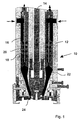
- a central sleeve 14 is enclosed in the housing 12 of the extrusion head 10 by the displaceable ejection piston.
- the sleeve 14 is also axially displaceable to adjust the gap width of the lower outlet nozzle 24.
- the melt-flowing plastic material streams to be processed are fed into the housing 12 from the extruders (not shown further) at the top (see arrows).
- the ejection piston consists of two concentric in this embodiment Pipe pieces 16 and 18. Each have a longitudinal groove - to compensate for the Piston stroke - the plastic material flows get into the discharge piston.
- the Spiral channel distributors each have at least four or more evenly the circumference distributed spiral channels. With increasing length of the spiral channels the depth of the spiral channels decreases steadily in the flow direction, whereby the Spiral channels at the top of the ejection piston individually with molten plastic melt be supplied.
- the coils of the two coil channel distributors are designed in opposite directions to one another.
- a comparatively thin cylindrical separating sleeve 20 is used, which separates the two circumferentially distributed melt flows within the ejection piston.
- the two melt streams purify and form a two-layer strand in the storage space 22 of the extrusion head 10 arranged below the ejection piston Plastic material instead, whereby the disadvantageous effect of the memory effect (swelling efforts to regain the previous shape) of the plastic material is significantly reduced.
- the adjustable outlet nozzle 24 is the plastic material is expressed as a tubular preform between the opened blow mold halves of a blow molding machine.
- the ejection piston is shown in its uppermost position in the left image and in its lowest position in the right half of the image.
- H is the length of the piston stroke.
- the separating sleeve 20 has an elongated design and projects through the front gap of the ejection piston by a small amount into the storage space. A union of the two plastic flows only takes place in the storage room. This is particularly important if two different materials with different viscosities or different melt index (MFI) are processed, so that no adverse mutual influence can take place during the circumferential distribution. The viscous material would displace the thin-flowing material. This could occur, for example, if a stress-crack-resistant A material (e.g.
- Lupolen 4261 A with high resistance to aggressive chemical liquids such as e.g. B. peracetic acid and on the outside a stiff Z material (e.g. Lupolen 5261 Z) with high strength values is processed in a two-layer strand into high-quality L-ring drums. Even with such problematic materials, a completely concentrically identical material distribution is achieved in the two layers in the hose or in the finished product. B. in a conventional double heart curve distributor.
- the separating sleeve 20 has, for example in the case of a 25 liter storage head, an average diameter of approximately 315 mm and a wall thickness (thickness) of 10 mm.
- FIG. 3 shows a further modified embodiment of the extrusion head 10 according to the invention.
- a displacement body 26 is formed and arranged at the free lower end of the separating sleeve 20, which protrudes into the storage space 22 below the ejection piston.
- the displacement body 26 is adapted to the contour of the lower end of the ejection piston and the region of the lower tapering storage space (22) and has a diamond-shaped or onion-shaped shape.
- the extrusion head according to the invention can advantageously be replaced by a conventional storage head by simply replacing existing blow molding machines. In this way, an effective increase in performance of the blow molding machine can be achieved with relatively low investment costs.
- a major advantage of the extrusion head according to the invention is furthermore that the sleeves used can be exchanged and adapted in length and shape to the material to be mainly processed in order to achieve the best processing results and the highest number of pieces.
Landscapes
- Engineering & Computer Science (AREA)
- Mechanical Engineering (AREA)
- Manufacturing & Machinery (AREA)
- Extrusion Moulding Of Plastics Or The Like (AREA)
- Blow-Moulding Or Thermoforming Of Plastics Or The Like (AREA)
- Processing And Handling Of Plastics And Other Materials For Molding In General (AREA)
- Glass Compositions (AREA)
- Seal Device For Vehicle (AREA)
Applications Claiming Priority (3)
| Application Number | Priority Date | Filing Date | Title |
|---|---|---|---|
| DE29906763 | 1999-04-16 | ||
| DE29906763U | 1999-04-16 | ||
| PCT/EP2000/003365 WO2000063000A1 (de) | 1999-04-16 | 2000-04-14 | Extrusionskopf |
Publications (2)
| Publication Number | Publication Date |
|---|---|
| EP1089864A1 EP1089864A1 (de) | 2001-04-11 |
| EP1089864B1 true EP1089864B1 (de) | 2002-07-31 |
Family
ID=8072291
Family Applications (1)
| Application Number | Title | Priority Date | Filing Date |
|---|---|---|---|
| EP00922636A Expired - Lifetime EP1089864B1 (de) | 1999-04-16 | 2000-04-14 | Extrusionskopf |
Country Status (9)
| Country | Link |
|---|---|
| US (1) | US6551089B1 (ja) |
| EP (1) | EP1089864B1 (ja) |
| JP (1) | JP4365041B2 (ja) |
| AT (1) | ATE221447T1 (ja) |
| AU (1) | AU4295700A (ja) |
| BR (1) | BR0006042B1 (ja) |
| CZ (1) | CZ296646B6 (ja) |
| DE (2) | DE10080969D2 (ja) |
| WO (1) | WO2000063000A1 (ja) |
Families Citing this family (11)
| Publication number | Priority date | Publication date | Assignee | Title |
|---|---|---|---|---|
| EP1426163A2 (de) * | 2002-12-04 | 2004-06-09 | Reifenhäuser GmbH & Co. Maschinenfabrik | Werkzeug zur Extrusion eines rohrförmigen Schmelzestranges |
| DE112006000926A5 (de) * | 2005-05-10 | 2008-04-03 | Mauser-Werke Gmbh | Extrusions-Speicherkopf und Verfahren zur Herstellung von blasgeformten mehrschichtigen Kunststoffhohlkörpern |
| CN104149319A (zh) * | 2014-08-07 | 2014-11-19 | 张家港市普信机械有限公司 | 一种吹塑机模头 |
| USD782771S1 (en) | 2015-04-03 | 2017-03-28 | Geo Plastics | Tight head drum |
| CN110239051B (zh) * | 2019-06-13 | 2021-01-19 | 开平雅琪塑胶机械模具厂 | 一种双层六机头塑料挤出机 |
| DE202019105681U1 (de) * | 2019-10-15 | 2021-01-19 | Kautex Maschinenbau Gmbh | Extrusionstechnik zur Bildung von Kunststoff-Vorformlingen und Schlauchbildungstechnik |
| DE202019105683U1 (de) * | 2019-10-15 | 2021-01-19 | Kautex Maschinenbau Gmbh | Extrusionstechnik zur Bildung von Kunststoff-Vorformlingen und Profilierungstechnik |
| USD938128S1 (en) | 2020-01-06 | 2021-12-07 | Geo Plastics | Nestable drum |
| USD1001413S1 (en) | 2020-06-30 | 2023-10-10 | Geo Plastics | Nestable drum |
| CN116277863B (zh) * | 2023-03-28 | 2023-08-25 | 石家庄星泉管业有限公司 | 一种新型环保树脂管道的挤出成型装置 |
| CN117400509B (zh) * | 2023-12-15 | 2024-02-23 | 四川省宜宾普什建材有限责任公司 | 一种具有导向输送结构的pe管材挤出成型装置及工艺 |
Family Cites Families (8)
| Publication number | Priority date | Publication date | Assignee | Title |
|---|---|---|---|---|
| US3023461A (en) | 1958-11-07 | 1962-03-06 | Owens Illinois Glass Co | Method for extruding plastic materials |
| DE2510127C2 (de) | 1975-03-06 | 1983-09-22 | Battenfeld Maschinenfabriken Gmbh, 5882 Meinerzhagen | Strangpreßkopf zum Herstellen eines aus zwei konzentrischen, mit ihren Fließnähten versetzt zueinander angeordneten Schichten bestehenden Verbundschlauches aus thermoplastischem Kunststoff |
| US4182603A (en) * | 1978-03-27 | 1980-01-08 | Egan Machinery Company | Multilayer tubular extrusion die |
| DE3623308A1 (de) * | 1986-07-11 | 1988-01-28 | Battenfeld Fischer Blasform | Strangpresskopf zur herstellung von verbundschlaeuchen aus unterschiedlichen thermoplastischen kunststoffmaterialien |
| DE4117083A1 (de) | 1990-06-01 | 1991-12-05 | Mauser Werke Gmbh | Speicherkopf fuer eine blasformmaschine |
| WO1991018731A1 (de) | 1990-06-01 | 1991-12-12 | Mauser-Werke Gmbh | Speicherkopf für eine blasformmaschine |
| US5262109A (en) * | 1992-10-19 | 1993-11-16 | James River Ii, Inc. | Method and apparatus for forming multilaminate film |
| US5690972A (en) * | 1996-07-01 | 1997-11-25 | Macro Engineering & Technology Inc. | Annular co-extrusion die |
-
2000
- 2000-04-14 JP JP2000612116A patent/JP4365041B2/ja not_active Expired - Lifetime
- 2000-04-14 AU AU42957/00A patent/AU4295700A/en not_active Abandoned
- 2000-04-14 BR BRPI0006042-9A patent/BR0006042B1/pt not_active IP Right Cessation
- 2000-04-14 DE DE10080969T patent/DE10080969D2/de not_active Expired - Fee Related
- 2000-04-14 EP EP00922636A patent/EP1089864B1/de not_active Expired - Lifetime
- 2000-04-14 AT AT00922636T patent/ATE221447T1/de active
- 2000-04-14 WO PCT/EP2000/003365 patent/WO2000063000A1/de active IP Right Grant
- 2000-04-14 DE DE50000331T patent/DE50000331D1/de not_active Expired - Lifetime
- 2000-04-14 CZ CZ20004674A patent/CZ296646B6/cs not_active IP Right Cessation
- 2000-04-14 US US09/719,649 patent/US6551089B1/en not_active Expired - Lifetime
Also Published As
| Publication number | Publication date |
|---|---|
| BR0006042A (pt) | 2001-03-13 |
| BR0006042B1 (pt) | 2010-12-28 |
| EP1089864A1 (de) | 2001-04-11 |
| CZ20004674A3 (en) | 2001-05-16 |
| WO2000063000A1 (de) | 2000-10-26 |
| US6551089B1 (en) | 2003-04-22 |
| DE10080969D2 (de) | 2001-09-27 |
| CZ296646B6 (cs) | 2006-05-17 |
| JP2002542070A (ja) | 2002-12-10 |
| AU4295700A (en) | 2000-11-02 |
| ATE221447T1 (de) | 2002-08-15 |
| JP4365041B2 (ja) | 2009-11-18 |
| DE50000331D1 (de) | 2002-09-05 |
Similar Documents
| Publication | Publication Date | Title |
|---|---|---|
| EP0486636B1 (de) | Speicherkopf für eine blasformmaschine | |
| EP0113041B1 (de) | Verfahren und Vorrichtung zur Bildung und Umschichtung von Teilströmen von aus bzw. in einer Strangpresse geförderten thermoplastischen und/oder elastomeren Massen | |
| EP1089864B1 (de) | Extrusionskopf | |
| EP0770469B1 (de) | Extrusionskopf zur Herstellung von schlauch- oder rohrförmigen Vorformlingen aus extrudierbarem Kunststoff | |
| DE3011425A1 (de) | Verfahren und vorrichtung zum herstellen von kunststoffrohren mit laengslaufenden hohlkanaelen in deren wandung | |
| EP0465889B1 (de) | Vorrichtung zum Herstellen von Hohlkörpern aus thermoplastischem Kunststoff | |
| DE3623308C2 (ja) | ||
| DE1233571B (de) | Verfahren und Vorrichtung zum Durchfuehren plastischen Materials von einer Plastifiziereinrichtung durch einen Durchflusskopf zu einer Duese zum Auspressen eines Stranges, insbesondere zum Herstellen eines Hohlkoerpers aus thermoplastischem Kunststoff nach dem Blasverfahren | |
| EP2032329B1 (de) | Formnestkavität mit mäanderförmigem kühlkanal | |
| DE4005437C2 (ja) | ||
| DE69218610T2 (de) | Speicherkopf für extrusions-blasformmaschine | |
| DE19719220C2 (de) | Querspritzkopf einer Extrusionsanlage | |
| EP1206341B1 (de) | Zylinder für einen doppelschneckenextruder | |
| EP0655312A1 (de) | Vorrichtung zum Herstellen eines schlauch- oder rohrförmigen Hohlstranges aus thermoplastischem Kunststoff | |
| DE2617898A1 (de) | Spritzkopf zum herstellen eines schlauchfoermigen stranges aus thermoplastischem kunststoff | |
| EP1498254B1 (de) | Extrusionskopf | |
| DE2428321A1 (de) | Mischvorrichtung fuer plastische, insbesondere thermoplastische oder nicht vernetzte elastomere massen | |
| DE69402245T2 (de) | Extrusionskopf für Mehrschichtvorformlinge aus instabilen Materialkombinationen | |
| EP0530582A1 (de) | Vorrichtung zum Verarbeiten von thermoplastischem Kunststoff mit einer Plastifiziereinheit | |
| DE4117083A1 (de) | Speicherkopf fuer eine blasformmaschine | |
| EP2049318B1 (de) | Spritzkopf für einen corrugator zur herstellung von kunststoffrohren | |
| EP2202046A1 (de) | Verfahren, Extrusionskopf und Vorrichtung für die Herstellung eines schlauchförmigen Formlings aus extrudierbarem Kunststoff | |
| DE102021118705A1 (de) | Vorrichtung und Verfahren für die biaxiale Kunststoff-Extrusion | |
| DE202021104605U1 (de) | Vorrichtung für die biaxiale Kunststoff-Extrusion | |
| US20030164581A1 (en) | Extrusion die for blow moulding and method for cleaning the extrusion die |
Legal Events
| Date | Code | Title | Description |
|---|---|---|---|
| PUAI | Public reference made under article 153(3) epc to a published international application that has entered the european phase |
Free format text: ORIGINAL CODE: 0009012 |
|
| 17P | Request for examination filed |
Effective date: 20001214 |
|
| AK | Designated contracting states |
Kind code of ref document: A1 Designated state(s): AT BE CH CY DE DK ES FI FR GB GR IE IT LI LU MC NL PT SE |
|
| GRAG | Despatch of communication of intention to grant |
Free format text: ORIGINAL CODE: EPIDOS AGRA |
|
| GRAG | Despatch of communication of intention to grant |
Free format text: ORIGINAL CODE: EPIDOS AGRA |
|
| GRAH | Despatch of communication of intention to grant a patent |
Free format text: ORIGINAL CODE: EPIDOS IGRA |
|
| 17Q | First examination report despatched |
Effective date: 20011002 |
|
| GRAH | Despatch of communication of intention to grant a patent |
Free format text: ORIGINAL CODE: EPIDOS IGRA |
|
| RAP1 | Party data changed (applicant data changed or rights of an application transferred) |
Owner name: MAUSER-WERKE GMBH & CO. KG |
|
| GRAA | (expected) grant |
Free format text: ORIGINAL CODE: 0009210 |
|
| AK | Designated contracting states |
Kind code of ref document: B1 Designated state(s): AT DE IT |
|
| REF | Corresponds to: |
Ref document number: 221447 Country of ref document: AT Date of ref document: 20020815 Kind code of ref document: T |
|
| REG | Reference to a national code |
Ref country code: IE Ref legal event code: FG4D Free format text: GERMAN |
|
| REF | Corresponds to: |
Ref document number: 50000331 Country of ref document: DE Date of ref document: 20020905 |
|
| REG | Reference to a national code |
Ref country code: IE Ref legal event code: FD4D Ref document number: 1089864E Country of ref document: IE |
|
| PLBE | No opposition filed within time limit |
Free format text: ORIGINAL CODE: 0009261 |
|
| STAA | Information on the status of an ep patent application or granted ep patent |
Free format text: STATUS: NO OPPOSITION FILED WITHIN TIME LIMIT |
|
| 26N | No opposition filed |
Effective date: 20030506 |
|
| PGFP | Annual fee paid to national office [announced via postgrant information from national office to epo] |
Ref country code: AT Payment date: 20110419 Year of fee payment: 12 |
|
| PGFP | Annual fee paid to national office [announced via postgrant information from national office to epo] |
Ref country code: IT Payment date: 20110421 Year of fee payment: 12 |
|
| REG | Reference to a national code |
Ref country code: AT Ref legal event code: MM01 Ref document number: 221447 Country of ref document: AT Kind code of ref document: T Effective date: 20120414 |
|
| PG25 | Lapsed in a contracting state [announced via postgrant information from national office to epo] |
Ref country code: AT Free format text: LAPSE BECAUSE OF NON-PAYMENT OF DUE FEES Effective date: 20120414 |
|
| PG25 | Lapsed in a contracting state [announced via postgrant information from national office to epo] |
Ref country code: IT Free format text: LAPSE BECAUSE OF NON-PAYMENT OF DUE FEES Effective date: 20120414 |
|
| REG | Reference to a national code |
Ref country code: DE Ref legal event code: R079 Ref document number: 50000331 Country of ref document: DE Free format text: PREVIOUS MAIN CLASS: B29C0047200000 Ipc: B29C0048320000 |
|
| PGFP | Annual fee paid to national office [announced via postgrant information from national office to epo] |
Ref country code: DE Payment date: 20190502 Year of fee payment: 20 |
|
| REG | Reference to a national code |
Ref country code: DE Ref legal event code: R071 Ref document number: 50000331 Country of ref document: DE |